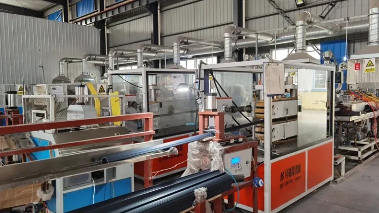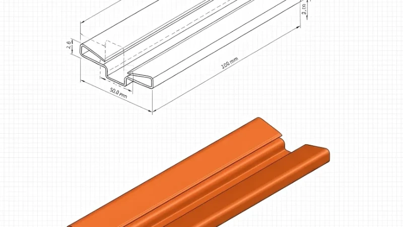
Most problems that show up on the production floor were decided months earlier, at the die head. Wall thickness that drifts across a section, corners that curl inward, a sealing lip that softens in heat — all trace back to choices made while designing the tooling and the sizing downstream of it. This guide explains how a die head actually works, which tooling styles fit which profiles, and how to set realistic tolerance expectations before your drawing reaches a supplier. It is written for procurement engineers, product designers and factory technical leads who are evaluating an extrusion partner or reviewing their own part design. For broader process context, start with our overview of plastic extrusion molding.
- A die head is a flow-distribution device: its job is to deliver melt of uniform temperature, pressure and velocity to every point of the profile cross-section, not merely to shape it.
- The die opening is always cut different from the final profile because melt swells at the die exit and the puller stretches the extrudate into the calibration sleeve.
- Well-designed profile extrusion can hold ±0.05 mm on cross-section dimensions, but only when material, section geometry and process window all support it.
- Co-extrusion tooling builds up to three layers in a single pass, so rigid and flexible materials can be combined in one profile instead of assembled later.
- Passing a first article proves the die works; it does not prove the process is stable, so ask for the process window behind the sample.
- Before comparing tooling prices, confirm what each quote includes: trials, first-article measurement, spare inserts and die maintenance are often priced separately.
What Does an Extrusion Die Head Actually Do?
It converts a cylindrical melt stream from the extruder into a shaped, continuous cross-section at uniform velocity. Inside the die head, melt is redirected into the profile geometry, distributed through the manifold and compressed through the land. Whatever unevenness the die leaves in flow or temperature appears downstream as wall-thickness variation, distortion or surface defects — no sizing tank can rescue a badly balanced die.
In practice, three functions happen in sequence. The adaptor evens out flow after the extruder and screen pack. The manifold distributes melt across the width of the profile, and for wide or asymmetric sections this is where most of the engineering effort goes. The land — the final parallel channel before the exit — sets the internal pressure that keeps the melt consolidated and gives the surface its finish. Lands that are too short leak pressure and produce rough, matte surfaces; lands that are too long push up head pressure and melt temperature, which risks degradation in heat-sensitive materials such as rigid PVC.
The other thing buyers should internalize is that a die opening never matches the drawing. It is deliberately cut to a different size and shape, because two effects change the melt after it leaves the tooling: swelling as oriented molecules relax at the exit, and stretching as the puller draws the profile into calibration. Managing both effects is what separates a die that converges after two or three cuts from one that needs weeks of trial and error.
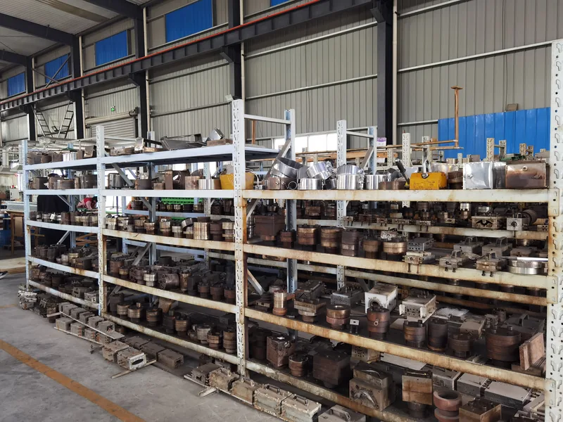
Die Head Types: Plate, Streamlined and Co-Extrusion Designs
Three tooling families cover most profile work. A plate die cuts the profile shape into flat plates stacked behind one another; it is inexpensive and quick to modify, but its abrupt flow transitions create dead spots where melt can stagnate and degrade. A streamlined die uses continuously curved flow channels with no sharp steps, which removes stagnation and gives the most consistent melt delivery, at a higher initial cost that pays back on long-running profiles.
A co-extrusion die head feeds two or three separate melt streams into one die body, layering materials such as a rigid shell with a flexible sealing lip in a single pass. It is the most complex of the three because each melt system needs its own temperature, pressure and layer-thickness control, and the layers must bond reliably at line speed.
| Die head type | Best suited for | Typical materials | Modification cost | Watch-outs |
|---|---|---|---|---|
| Plate die | Simple sections, short runs | PVC, PE, PP | Low; re-cut individual plates | Dead spots can degrade heat-sensitive melts |
| Streamlined die | Long-running, complex profiles | Rigid PVC, ABS, PC, PA6 | Higher; full rework | Longer lead time to first cut |
| Co-extrusion die head | Multi-material sections, sealing lips | PP+TPV, ABS+TPU, PVC+TPU | Highest; two melt systems to balance | Layer thickness needs its own control loop |
Custom non-standard sections are developed directly from the customer drawing, and the choice between plate and streamlined design is normally made against expected run length: the longer the program, the more a streamlined extrusion die earns back its higher initial cost through lower scrap and fewer restarts. Volume and material, not habit, should decide the tooling style.
"Co-extrusion always costs less than assembling two parts."False
Layering materials in one die head adds a second melt system, its own control loop and more trial time. At low volumes the tooling premium can exceed what assembly saves, so the break-even depends on run length.
"Co-extrusion pays back on long-running sealing profiles."True
When program volume is high, one bonded profile removes an assembly step and its failure interface while cutting cost per meter. For short runs, a simpler die plus secondary assembly is often the honest recommendation.
The economics also depend on what happens after the die: secondary bonding, assembly labor and the inventory of two part numbers all carry hidden costs that a single co-extruded profile eliminates. That is why tooling options should be compared at the program level, not at the tool price level.
ZetarVac runs single, double and triple layer extrusion, including up to 3 layers in a single co-extrusion pass, with combinations actually in production such as PP+TPV, PP+TPE, PVC+TPU, ABS+TPU and TPV+CPVC. For a buyer, that means a function that used to require assembly — a rigid rail with a flexible sealing lip — can be produced as one continuous extruded profile.
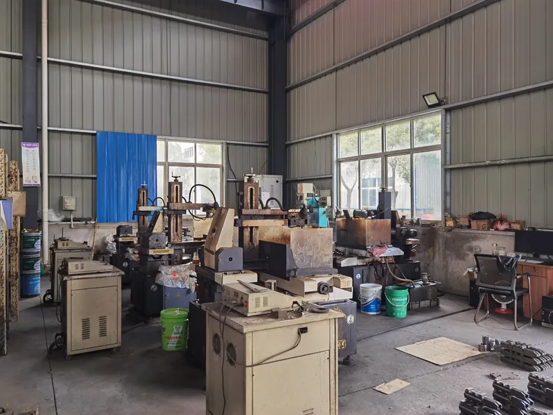
How Do Swell, Draw-Down and Land Length Shape Your Profile?
Die swell, draw-down and land length decide the final dimensions together. The melt swells roughly 10–30% on exit depending on material and shear history, and the puller then stretches the profile back toward the calibration size. The die opening must be sized so that swell minus draw-down lands on the drawing, with the land tuned to control how much swell remains.
Die swell is not a defect; it is elastic recovery1. Molecules oriented in the land relax the moment they leave confinement, so the extrudate grows in thickness and shrinks in width. High-viscosity melts swell more, while long lands and low shear rates swell less. The same drawing cannot simply reuse a die designed for a different material, because swell behavior moves with the compound.
Draw-down ratio2 describes how much the puller stretches the extrudate relative to the die opening. For profiles, a moderate DDR — commonly around 1.05–1.3 depending on material and section — keeps the melt compacted and dimensional, while excessive draw-down thins walls unevenly, distorts corners and locks in internal stress. Draw-down balance between the width and thickness directions matters just as much on asymmetric sections: unbalanced draw-down is the classic cause of a profile that bows the moment it leaves the sizing sleeve.
Land length is where you buy back control. A longer land raises head pressure, reduces swell and improves surface finish; a shorter land lowers pressure and temperature. As a rule of thumb, the land-to-gap ratio in profile dies sits roughly between 10:1 and 20:1, adjusted per material — rigid PVC runs shorter lands to limit residence time and heat, while polyolefins tolerate longer lands. These are starting points for die trials, not finished numbers.
"A longer land length always gives tighter tolerances."False
Extra land raises melt pressure and temperature, which can degrade heat-sensitive compounds and destabilize the flow itself. The right land length is material-specific; more length simply moves the problem from swell to degradation.
"Land length is tuned per material and section, not maximized."True
A competent die maker selects the land-to-gap ratio from the compound viscosity, thermal sensitivity and the section geometry, then verifies it on the trial profile. Treating land length as a fixed rule produces either rough surfaces or degraded melt.
Designing for Tolerance: What Can You Realistically Hold?
Well-designed profile extrusion can hold ±0.05 mm on critical cross-section dimensions, subject to material and section geometry. Uniform wall thickness, generous radii and symmetric sections tolerate far tighter control than thin, heavily asymmetric sections with sharp internal corners and mixed thick-and-thin walls.
The phrase subject to material and section geometry does real work there. Amorphous materials such as rigid PVC, ABS and PC hold tolerance more predictably than semi-crystalline ones such as PP and PA, whose shrinkage varies with cooling rate and crystallinity. Geometry matters just as much: a profile with one thick wall and one thin wall will shrink unevenly and bow whatever the die head does. Most tolerance disputes are prevented before die steel is cut, which is why our DFM checklist for extruded profiles and extrusion dies covers the drawing reviews that catch these issues early.
For material-dependent performance limits, recognized standards give buyers a shared baseline rather than supplier promises. For rigid PVC window and door profiles, EN 126083 specifies the profile geometry, impact resistance and heat reversion that the finished extruded profile must demonstrate, which means the die head and the downstream sizing and cooling have to be engineered toward those verification methods from the start. The PVC-U compound itself is designated and specified under ISO 11634, so both sides can name the material unambiguously on the drawing.
ZetarVac commits to a minimum dimensional tolerance of ±0.05 mm on the profile cross-section, with profile widths from 5 to 600 mm, subject to material and section geometry. When a supplier quotes tolerance, ask which dimensions the number applies to: overall width, functional gaps and wall thickness rarely behave the same way.
In practice, tolerance capability is proven during die trials: measure the profile at several points along the line, correlate the readings with melt temperature and vacuum settings, and record which setpoints deliver drawing conformity. That record becomes the process window handed to production, and the reference point for every reorder.
"If the first article passes, production will stay in tolerance."False
A first article is a snapshot taken with a tuned process, sometimes with hand-adjusted conditions. Without a documented process window for melt temperature, vacuum and line speed, normal drift will push the extruded profile out of tolerance within hours.
"Ask for the process window, not just the first article."True
A stable design comes with documented setpoints and the boundaries within which the profile still meets drawing. That window is what holds tolerance across shifts, material lots and seasons, and it is what you should request before approving tooling.
Common Failure Modes and Inspection Checks
Most die head problems appear as a short list of symptoms, each with a distinct cause. Wall-thickness imbalance across the section points to flow distribution, not to the puller: measure the wall at fixed points, then open or restrict the corresponding manifold channels and re-trial. Die lines, gels and matte patches point to stagnation or overheating, most often in plate dies with dead spots, and they are checked by lowering melt temperature and inspecting the flow channel. Bow and twist come from uneven cooling or unbalanced draw-down, verified by checking vacuum distribution and water temperature zone by zone. Surface roughness at high line speeds — sharkskin — indicates excessive shear at the land exit.
Dimensional drift over hours is the most subtle failure: the profile was right at start-up and wrong after lunch. It usually traces to melt temperature creep, vacuum level changes or material moisture, all of which argue for logging setpoints rather than trusting dials. Inline laser gauges mounted after the calibration sleeve track critical dimensions continuously, and a simple SPC5 chart on wall thickness at two or three fixed points reveals flow imbalance long before scrap accumulates. Offline, a profile projector checks the full cross-section against the drawing.
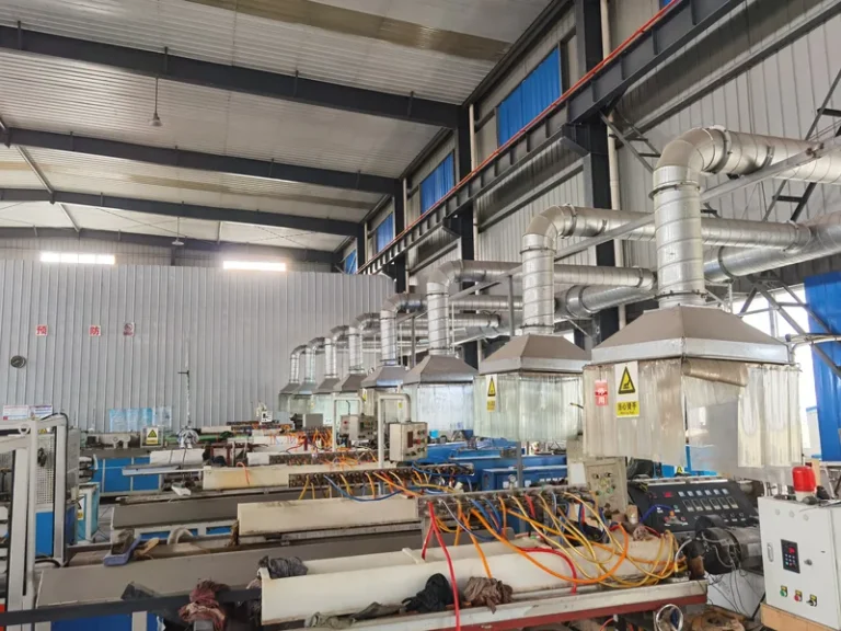
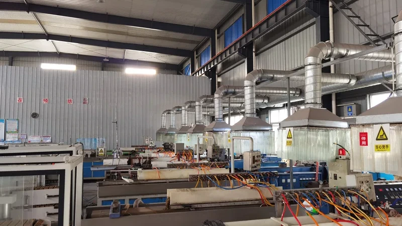
ZetarVac runs 7+ automated extrusion lines with in-line punching, embossing and printing, and the plant holds 45+ production lines in total with reference monthly capacity of about 300–500 tonnes across the extrusion lines. In-line secondary operations only make economic sense once the base extruded profile is dimensionally stable, which is exactly where die head quality shows up in the quotation.
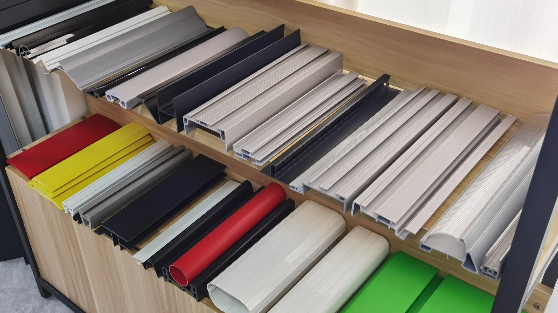
Two production examples show how these choices pay off. An automotive seat slide rail strip combines PP and TPV in one co-extrusion pass: the PP carries structural load while the TPV lip delivers dust exclusion, guiding, wear resistance and low friction. A robot vacuum squeegee strip does the same with ABS and TPU — rigid ABS support behind a flexible, wear-resistant wiping contact. On simpler sections, a transparent PVC tube profile for cable protection and a PVC drainage channel profile both run single-layer extrusion, one for electrical insulation and guiding, the other for continuous water diversion in building systems.
FAQ
How long does it take to develop a die head for a new profile?
Simple sections based on a proven die family can reach first trials in a matter of weeks, while complex co-extrusion tooling takes longer because two melt streams must be balanced and the die usually needs one or two re-cuts. The schedule depends far more on section complexity and material than on profile width.
What information do you need to quote a profile die?
A 2D drawing with dimensions, tolerances and material grade is the minimum; expected annual volume and the application environment decide the tooling style. Drawings without tolerance priorities force the die maker to over-engineer everything, which shows up in the price. Prototyping, small batch and large batch production are all supported, and our extrusion capabilities page lists what is available in-house.
Can one die head run profiles in different materials?
Occasionally yes within a material family, but changing between, say, rigid PVC and PP normally requires a new die because swell, shrinkage and thermal behavior differ. A die designed for PVC cannot be assumed to run PP: the opening compensation, land length and sizing all shift.
Is co-extrusion tooling worth the cost for a sealing profile?
Compare it against assembly. Bonding or clipping a separate seal onto a rigid profile adds a process step, a failure interface and a two-part inventory; where volumes justify it, a co-extrusion die head producing one bonded profile is usually cheaper per meter and removes the assembly defect mode entirely.
What tolerance should I put on my profile drawing?
Mark only the functionally critical dimensions tight and give the rest general profile tolerances. Putting ±0.05 mm on every dimension makes the tooling and the process window unnecessarily expensive; tolerance grades should follow the function of each surface, not drafting habit.
If you are comparing suppliers or reviewing your drawing, share your drawings and talk to an engineer about the die head approach, tolerance grades and material options for your section. ZetarVac’s team can evaluate your profile project against your application requirements before any steel is cut.
-
Die swell: The elastic expansion of extruded melt immediately after it leaves the die, as oriented molecules relax. ↩
-
Draw-down ratio (DDR): The ratio between the die opening size and the final product size, describing how much the puller stretches the extrudate. ↩
-
EN 12608: European standard for PVC-U window and door profiles, specifying profile geometry, impact resistance and heat reversion. ↩
-
ISO 1163: Standard for unplasticized PVC (PVC-U) moulding and extrusion materials, covering designation and specification. ↩
-
SPC: Statistical process control, the use of control charts to monitor process stability over time. ↩