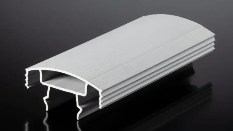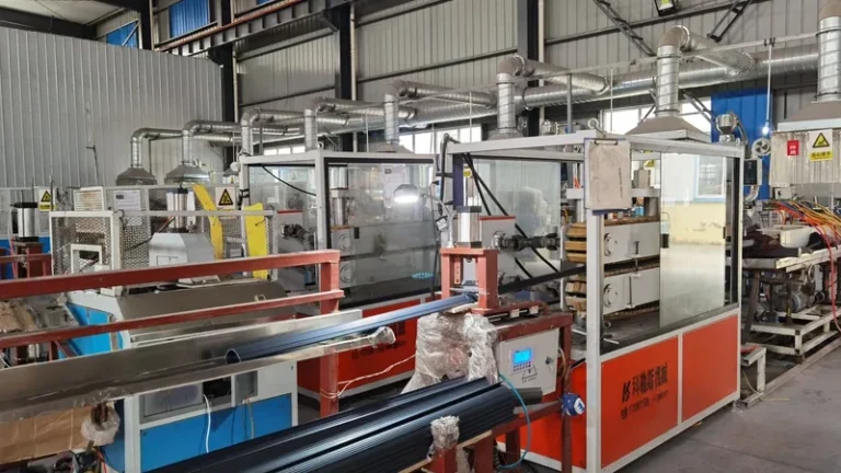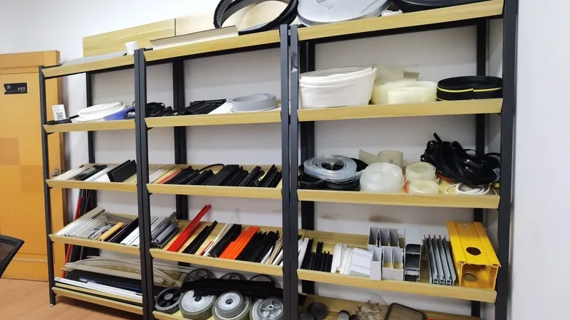
Most of the cost and risk in a profile extrusion project is committed before any die steel is cut. Design for Manufacturability, usually shortened to DFM1, is the discipline of surfacing those commitments while they still cost a drawing revision instead of a die rebuild. This checklist covers the decisions that matter for extruded plastic profiles and the extrusion dies that produce them: section geometry, tolerance architecture, material data, line readiness, and what a first article can realistically prove. It is written for procurement engineers, product designers, and factory technical managers who have to sign off before tooling spend.
- Review wall transitions, section balance, and the cooling concept before die design; these three choices drive most die-touch iterations.
- Freeze the tolerance hierarchy, material data, and measurement plan in one release package before the extrusion die is machined.
- Assign tolerances by feature function. Capability such as ±0.05 mm on a cross-section depends on material and section geometry, not on goodwill.
- Declare co-extrusion intentions early; layer count and material pairings change the die head, the sizing, and the quote.
- Judge the pilot by trend data over time, not by a single passing first article.
- Put in-line operations such as punching, embossing, and printing into the DFM scope from day one, because they shape the line layout.
Which Geometry Choices Drive the Risk in an Extrusion Die?
Wall transitions, section balance, and the cooling concept carry most of the die risk. A profile that flows evenly and solidifies uniformly needs fewer corrections than one optimized only on screen. Before the extrusion die is designed, decide the wall map, the transition radii, and how the section will be cooled and pulled; those three decisions set the ceiling on everything downstream.
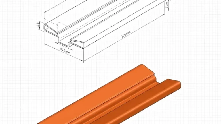
Start with a wall map. Practical wall thickness for most extruded profiles sits roughly between 1.5 and 8 mm, depending on material and equipment. Thinner walls amplify sensitivity to thermal disturbance, while thicker walls raise puller load and cooling time. Sharp jumps between thick and thin zones concentrate flow and solidify at different rates, which is where edge waviness, sink-like depressions, and out-of-flat sections appear first.
Balance matters as much as wall thickness. Long unsupported flats, deep channels, and asymmetric legs cool unevenly and show up as bow, twist, or camber along the length. Where a wall change is unavoidable, add a generous radius and a transition length instead of a step. Mark every abrupt transition on the drawing and estimate the thickness ratio across it before the die head design starts.
"A symmetric CAD section always extrudes symmetrically."False
Symmetry on the drawing does not survive contact with gravity, uneven cooling, and haul-off tension. The heavier leg solidifies slower and shrinks differently, and the result is bow, twist, or camber that appears meters downstream of the die.
"Balanced walls around the neutral axis reduce bow and camber in long profiles."True
Even wall distribution makes cooling more uniform across the section, so differential shrinkage — the actual cause of long-form distortion — has less to work with. This is the cheapest distortion fix available, because it costs a design change rather than die steel.
If geometry review keeps flagging the same transitions, schedule a design iteration before the die is quoted. Late die modifications remain possible, but they consume pilot time and budget faster than any other correction on the list.
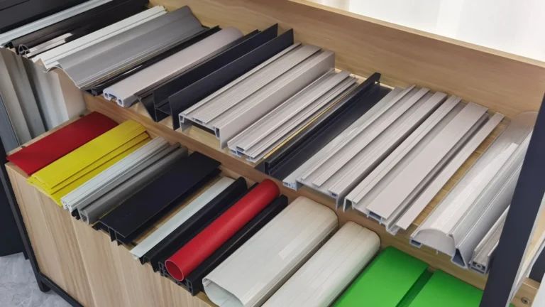
ZetarVac extrudes profile widths from 5 to 600 mm and develops non-standard sections to customer drawings, in single-layer or multi-layer co-extrusion. That envelope means geometry review should concentrate on what makes your section unusual — its transitions, its balance, its cooling — rather than on whether the size itself fits the machine.
Which Tolerances Must Be Frozen Before the Die Head Is Cut?
The tolerance hierarchy, the material data, and the measurement plan form one release package that must be frozen before die construction starts. Anything left ambiguous at this point becomes a change request that procurement inherits later, and change requests after the extrusion die exists are the most expensive kind.
Build the package around feature function. Sealing lips, mounting references, and mating interfaces deserve tight control and frequent checks; decorative edges usually do not. A structured GD&T2 scheme with a clear datum hierarchy does more to prevent production arguments than extra test coupons, because it fixes which dimensions are critical and why.
For some product families, published standards set the baseline. For PVC-U window and door profiles, EN 126083 defines the profile geometry, impact resistance, and heat reversion requirements the finished extrusion must meet, so the drawing should reference the standard instead of inventing parallel limits. Where mechanical strength is specified, ASTM D6384 is the default tensile test cited for extruded profiles, and the drawing should state which method applies rather than quoting an unlabeled number.
| Tolerance class | Typical features | Control approach |
|---|---|---|
| General | Cosmetic edges, non-mating surfaces | Standard process capability, first article plus periodic checks |
| Functional | Sealing lips, sliding guides, snap features | Tighter band, defined GD&T datums, in-line gauging |
| Critical | Mating interfaces, assembly datums | Frozen before die build, Cpk targets, trend-based escalation |
| Reference | Informational dimensions | Measured for record only, no acceptance action |
Material data belongs in the same package: base resin, melt flow index5 range, density, and moisture sensitivity. Two batches of the same resin with different flow behavior can fill the same die head differently, so the quoted range is part of the tolerance story, not supplier paperwork.
"A precision-machined die guarantees tight tolerances on any profile."False
The die is only half of the dimensional story. Melt behavior, cooling balance, and haul-off stability determine how the section actually solidifies, so tolerance capability depends on the material and the section geometry, not on machining alone.
"Tolerance limits should be assigned by feature function, not spread uniformly across the drawing."True
Critical fits need measurement logic and check frequency matched to their risk; cosmetic edges rarely do. A written hierarchy makes corrective actions faster and auditable, while a flat tolerance everywhere hides which features actually matter.
None of this makes tight tolerances unattainable; it makes them a purchasing decision. Tolerance class, section complexity, and material choice drive the quote together — the custom profile extrusion cost breakdown shows how those factors interact before any commitment is made.
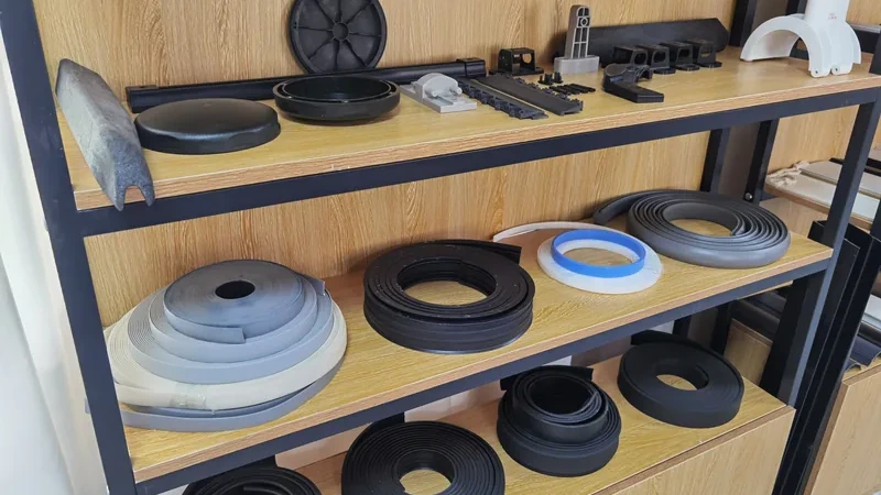
ZetarVac runs co-extrusion combinations including PP+TPV, PP+TPE, PVC+TPU, ABS+TPU, and TPV+CPVC, with up to three layers in a single pass. For a DFM review, that means rigid-support-plus-soft-lip constructions are standard work, and the material pairing decision belongs in the drawing package before quoting, not after.
What Should the Line Readiness Review Cover Before a Pilot Run?
Line readiness covers everything the profile touches after the die head: sizing, cooling, haul-off, and any in-line operation. Review it before the pilot so the measurements come from a stable baseline instead of a moving one.
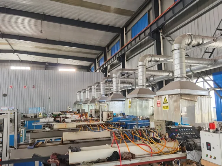
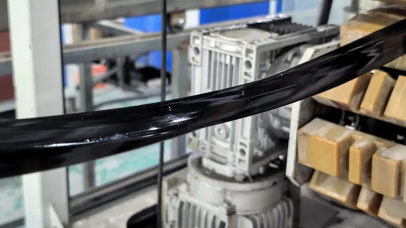
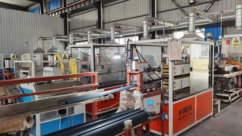
A profile extrusion line is a chain of thermal and mechanical stages. The die head zones, the vacuum sizing table, the cooling baths, and the dual-belt haul-off each add their own variation, and melt temperature, vacuum level, and pull speed interact. Write acceptance bands for the whole chain rather than for one machine; exact set-points depend on material and equipment, which is why they belong in the process envelope rather than in a fixed checklist value.
Confirm the calibration items explicitly: die alignment, puller tension, sensor zeroing, and gauging readiness at the inspection station. If any of these is unverified, the pilot produces precise numbers from an unstable baseline, and every later trend reading inherits that doubt.
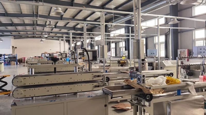
ZetarVac runs 7+ automated extrusion lines with punching, embossing, and printing available as in-line operations, within a plant of 45+ production lines total. For DFM, that means secondary operations can be integrated into the line layout — but only when they are specified before the line is set up, not after the profile already runs.
How Do You Know a First Article Proves a Stable Process?
Strictly, it does not — and that is the point. A first article shows the setup can produce a conforming profile once; process stability is a statement about time, and only trend evidence supports it.
During the pilot, keep sampling density high during the first hour and narrow it only after the trend stabilizes. Profiles keep changing as line heat soaks in; a section that measures in-spec at startup can drift an hour later as zones equalize. For critical dimensions, plot values over time and escalate on slope, not only on limit breach.
Separate one-off misses from sustained movement. A single outlier can stay in the correction queue with a written observation; a repeated directional trend on the same feature across two intervals should stop the line for a root-cause pass. Tie each critical dimension to a Cpk6 target and an action rule in advance, so pilot feedback becomes data instead of negotiation.
"One passing first article is enough to release a profile to volume."False
A single lot cannot show thermal drift, material-lot variation, or operator effects, all of which appear over time. Releasing on one lot tends to move the instability into full-scale production, where every correction costs more.
"Trend-based escalation catches process drift earlier than limit-only acceptance."True
Limits react after the breach; trends react on the slope, before the breach. That gap is where preventive adjustment happens, and it is usually the difference between a planned tweak and a pile of scrap.
When the buyer is ready to compare suppliers, the DFM package itself becomes the test: a manufacturer who engages with the tolerance hierarchy and the process envelope is more useful than one who only prices the drawing. The questions worth asking a China plastic extrusion manufacturer before tooling spend are exactly the ones this checklist raises.
FAQ
How tight can profile tolerances realistically be?
It depends on material and section geometry. On the profile cross-section, ±0.05 mm is the minimum achievable tolerance under favorable material and geometry conditions; simpler sections in stable materials hold it comfortably, while thin walls, long flats, or softer compounds may not. Freeze the tight bands only on features that functionally need them.
What profile sizes can be extruded?
Profile widths from 5 to 600 mm are within the working envelope, including custom non-standard sections developed to customer drawings. The constraint to check in DFM is usually not the size itself but how the section balances and cools at that scale.
Should co-extrusion be decided during DFM?
Yes. Layer count — single, double, or triple, up to three layers in one pass — and the material pairing change the die design, the sizing, and the quote. Declaring the soft-lip or dual-hardness intent early lets the die head and the process envelope be designed around it instead of retrofitting later.
What information should I bring to a first DFM review?
Bring the CAD with critical dimensions marked, the material family or candidate materials, the service environment including temperature, load, and outdoor exposure, target volumes, and any mating or sealing interfaces. Prototyping, small batch, and large batch production are all supported, so the review can happen before any volume commitment exists.
Where can I go deeper on profile extrusion before sending drawings?
Explore the full process overview on the plastic extrusion molding page, which walks through the capabilities, materials, and application areas behind this checklist. Reviewing it alongside your wall map and tolerance hierarchy is the most useful preparation for a structured DFM discussion.
-
DFM: Design for Manufacturability, the practice of designing a part so it can be produced reliably and economically with a chosen process. ↩
-
GD&T: Geometric Dimensioning and Tolerancing, a standardized system for defining tolerances on geometry and form. ↩
-
EN 12608: European standard for PVC-U profiles for windows and doors, covering profile geometry, impact resistance, and heat reversion. ↩
-
ASTM D638: Standard test method for tensile properties of plastics, the default tensile test cited for extruded profiles. ↩
-
MFI: Melt Flow Index, a measure of polymer flow behavior under standard test conditions. ↩
-
Cpk: Process capability index comparing the process mean and spread against specification limits. ↩