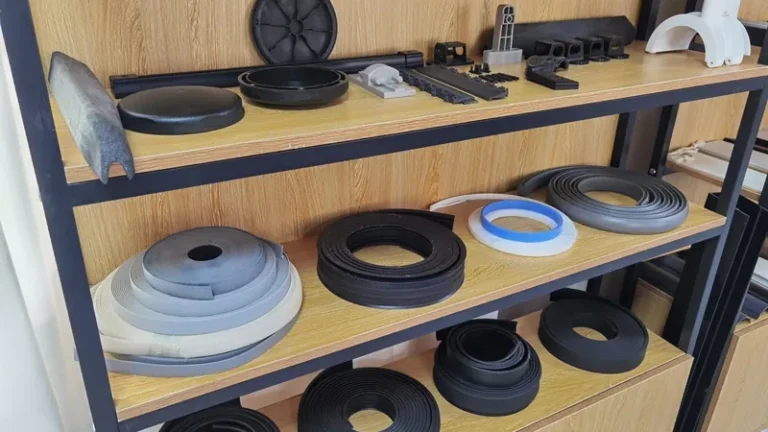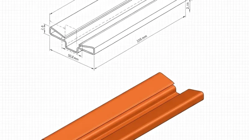
Tolerance problems rarely start on the shop floor. They start on the drawing, when a shrinkage value nobody discussed quietly turns a tight dimension into something noticeably larger three meters downstream of the die. Plastic extrusion is a continuous, hot, moving process: the melt leaves the extrusion die far above room temperature, gets sized and cooled, and keeps contracting long after it looks finished.
Once you understand where that movement comes from and how a profile extrusion line compensates for it, you can write tolerances the process can actually hold — and you know which inspection points prove it. For background on the process family itself, start with our plastic extrusion molding overview; this guide then goes deep on shrinkage behavior, tolerance expectations by material, and the controls that keep an extruded profile in specification across a full run.
- Extrusion shrinkage combines thermal contraction with crystallization and ranges from roughly 0.2–0.6% for amorphous materials such as rigid PVC to 1.0–4.0% for semi-crystalline PP and HDPE.
- Die and calibration geometry are deliberately sized to compensate for shrinkage, so the die opening is not the final dimension of the profile.
- Vacuum calibration and uniform cooling perform the final dimensional correction; uneven cooling is the most common cause of warp, crook and twist.
- A ±0.05 mm tolerance on the profile cross-section is achievable, but only for suitable materials and section geometry.
- Place tight tolerances only on functional surfaces, and verify stability with periodic in-line measurement rather than a single first-article report.
Why Extruded Profiles Move After They Leave the Die
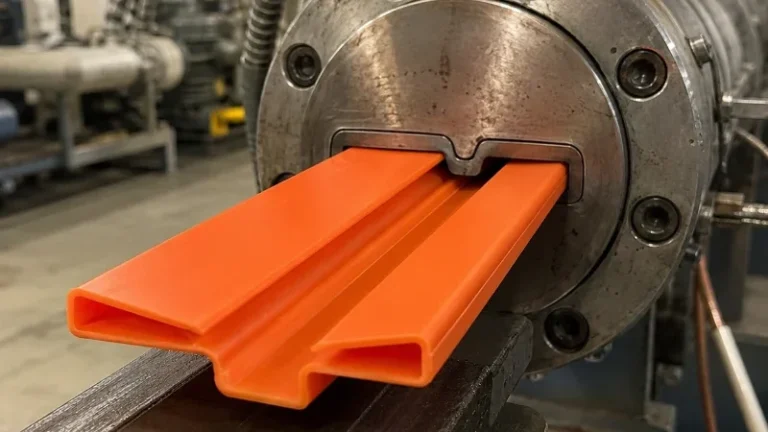
The melt enters the die head at roughly 170–230 °C depending on the polymer, exits under pressure, and swells slightly as molecular orientation from shear relaxes. From that moment two things happen at once: thermal contraction as the profile cools toward room temperature, and, for semi-crystalline materials, additional shrinkage as polymer chains pack into crystals. Amorphous materials such as rigid PVC and ABS only contract thermally, which is why they are the more dimensionally stable family for tight tolerance work.
The physics is simple enough to estimate. Linear thermal contraction is approximately the coefficient of thermal expansion multiplied by the temperature drop, and the crystallization contribution for PP or HDPE adds several times that amount. This is why an identical cross-section run in PVC and in HDPE needs different die land sizes, different calibration sleeves, and different tolerance expectations on the drawing.
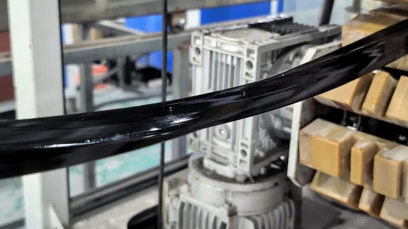
Shrinkage becomes an engineering problem when it is uneven. A profile with thick and thin walls, or with hollow chambers, cools at different rates through its section, so one face shrinks more than another and the part bows, crooks or twists as it reaches equilibrium. Wall thickness transitions, not the average shrinkage value, cause most straightness complaints on extruded profile projects. The fix lives in die design and uniform cooling, not in re-measuring.
"Extrusion shrinkage is unpredictable, so mating parts should always be designed with generous clearance."False
Shrinkage for a fixed polymer, melt temperature and cooling setup is highly repeatable, and die designers calculate it into the tooling before cutting steel. Treating it as random forces late fitting changes and rework that cost far more than agreeing the shrinkage value at drawing review.
"Shrinkage should be agreed as a material-and-process value before the die is cut."True
When buyer and extruder agree on the polymer, expected shrinkage range and calibration approach upfront, the die and calibrator are sized to land on nominal after cooling. Shrinkage becomes a design input instead of a surprise during pilot runs.
How Much Shrinkage Should You Expect in Profile Extrusion?
For common profile materials, expect roughly 0.2–0.6% for amorphous polymers such as rigid PVC, ABS and PC, and roughly 1.0–4.0% for semi-crystalline polymers such as PP and HDPE. The exact value depends on melt temperature, cooling rate and section geometry, so treat published figures as a starting point for tooling design, not a guarantee.
The amorphous versus semi-crystalline split matters more than the compound brand. Semi-crystalline profiles also keep moving after they feel cold: a thick PP or HDPE profile can continue settling for a day or longer as crystallization completes at room temperature. Amorphous profiles stabilize much sooner, which shortens the wait before first-article measurement and reduces the risk of a part drifting after approval.
| Material | Typical shrinkage range | Tolerance behavior | Common profile uses |
|---|---|---|---|
| Rigid PVC (PVC-U) | 0.2–0.6% | Most stable; suits tight cross-section tolerances | Window and door profiles, drainage channels, sealing strips |
| ABS | 0.4–0.7% | Stable; common rigid layer in co-extrusion | Industrial and automotive profiles, decorative parts |
| PC / PMMA | 0.5–0.8% | Needs slow, even cooling to stay clear and flat | Transparent pipes, light covers, clear profiles |
| PP | 1.0–2.5% | Higher shrink and post-cooling movement | Profiles, pipes, functional parts, seat rail strips |
| HDPE | 1.5–4.0% | Largest movement; expect wider tolerances | Pipes, edge trims, guide rails, wear strips |
For rigid PVC-U window and door profiles specifically, EN 12608 specifies the profile geometry, impact resistance and heat reversion requirements, which together bound how much dimensional movement a finished profile may still show after extrusion and service aging.1 Heat-related softening is assessed separately: ISO 306 defines the Vicat softening temperature, a practical indicator of how far a compound can soften and creep under heat before its dimensions drift.2
What Does a ±0.05 mm Tolerance Actually Commit the Supplier To?
A ±0.05 mm commitment on the profile cross-section commits the supplier to controlling melt temperature, die geometry, vacuum calibration and cooling as one system, and to holding that control for the whole run. It is achievable on suitable materials and section geometry, and both conditions should be confirmed at drawing review before the tolerance goes on the print.
Practically, that tolerance requires a stable melt with tight temperature control, a die land and flow distributor cut for the specific compound, and a vacuum calibration section that corrects the hot profile against sized surfaces. It also requires in-line dimensional measurement, because a continuous process drifts: die wear, melt temperature fluctuation and cooling water temperature all move the profile slowly over a shift.
ZetarVac extrudes profiles from 5 mm to 600 mm in width with a minimum achievable cross-section tolerance of ±0.05 mm, subject to material and section geometry. That qualification is the honest part of the sentence: the same tolerance that is routine on a simple solid strip may be unrealistic on a thin-walled multi-chamber section, which is exactly why tolerance should be discussed against the actual drawing, not in the abstract.
Section geometry drives the difficulty. A solid strip or simple U-channel holds tight tolerance readily; a profile with large hollow chambers, thin webs and abrupt wall transitions gives the calibration sleeve less surface to work against and gives uneven cooling more leverage. Width matters too — very narrow profiles amplify measurement resolution, very wide ones amplify differential cooling.
"Tightening every tolerance on the drawing is the cheapest way to protect assembly quality."False
Blanket tight tolerances force slower line speeds, tighter calibration windows and more inspection on surfaces no mating part ever touches. The cost and reject risk land on every meter of the run, including the surfaces that never mattered to the assembly.
"Tight tolerances belong only on functional surfaces that mating or guidance depends on."True
Assign critical tolerances to slide rails, seal lips, clip features and mating faces, and let the rest of the profile carry standard commercial tolerances. The extruder then spends process capability where it counts, and the assembly still fits.
Die, Calibration, and Cooling: Where Tolerance Is Actually Won
Compensation starts at the die head. The designer sizes the land and orifice larger than nominal to account for die swell and shrinkage, balances flow so the melt exits uniformly across the width, and sets a draw-down ratio the take-up can hold. A poorly balanced flow distributor cannot be fixed downstream: if one leg of the profile exits slightly thick, calibration can only correct so much before vacuum marks or built-in stress appear.
These die head decisions — land length, flow balance, compression ratio — are covered in detail in our extrusion die head design guide. The sizing stage then does the actual dimensional correction. In vacuum calibration, the hot profile passes through calibration sleeves while vacuum pulls its outer surfaces against water-cooled sizing surfaces; common engineering practice runs vacuum in the range of roughly 20–80 kPa depending on section stiffness and wall thickness. Dry calibration suits rigid sections, and a water bath finishes the cooling.
Sleeve dimensions are cut from the same shrinkage compensation logic as the die, which is why changing material late in a project usually means re-cutting tooling. Our vacuum calibration tank guide for profile extrusion covers this sizing stage in depth.
Cooling uniformity decides whether corrected dimensions survive. Asymmetric water temperature or contact lets one side freeze before the other, locking in bow and internal stress that shows up hours later as crook on the packing bench. In-line secondary operations — punching, embossing and printing — must sit downstream of dimensional stability, because locating holes punched into a still-moving profile will not land where the drawing says.
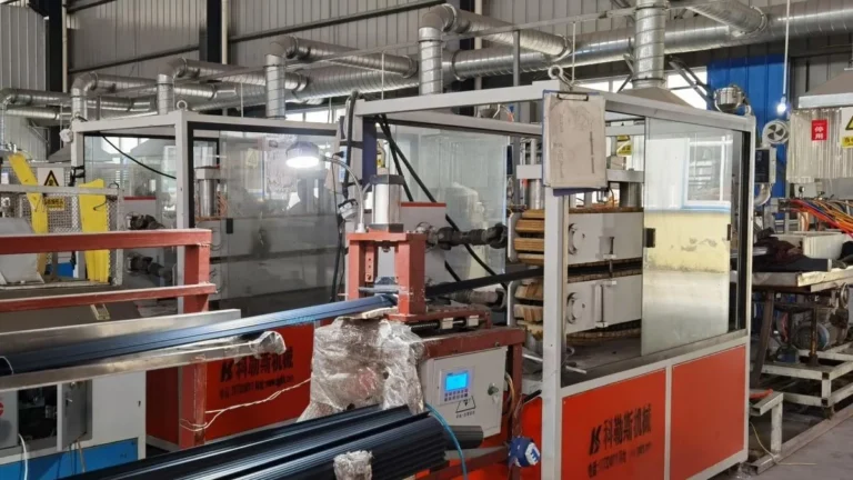
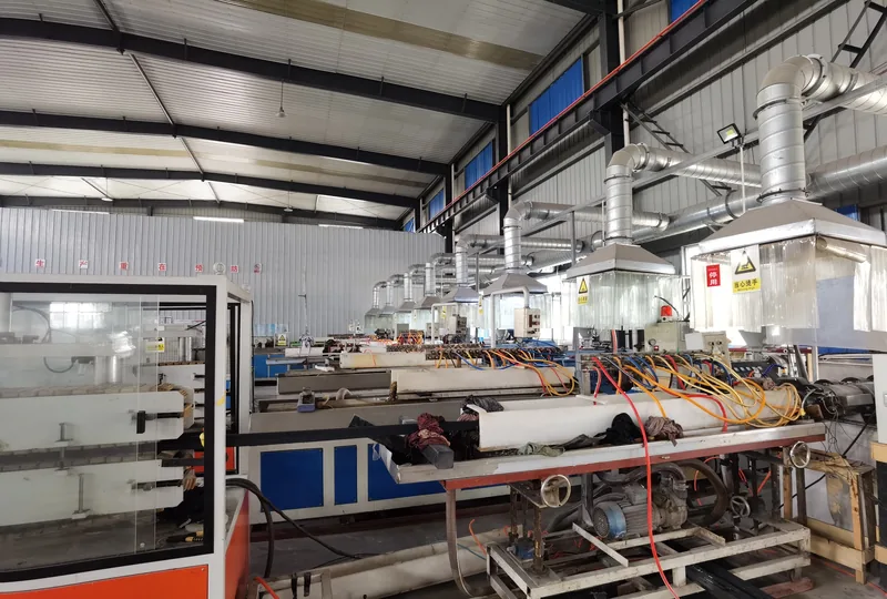
That tolerance capability is produced by equipment, not intentions: the extrusion plant runs 7+ automated lines with a maximum profile width of 600 mm, and punching, embossing and printing are performed in-line. Across the wider plant, 45+ production lines support prototyping, small batch and large batch programs under the same process discipline.
How Material and Co-extrusion Choices Change the Tolerance Budget
Material selection sets the ceiling on achievable tolerance before tooling is touched. Rigid amorphous compounds hold the tightest limits; highly crystalline and rubber-modified compounds need more room. Fillers complicate the picture in both directions: glass fiber in PP/GF profiles reduces overall shrinkage but introduces direction-dependent movement, which the die designer must anticipate rather than average out.
Co-extrusion adds a second variable: two materials shrinking at different rates in one bonded section. A soft TPE or TPV sealing lip over a rigid core contracts differently than the substrate, so the tolerance budget must absorb that differential — usually by tolerating the soft lip more generously and holding the rigid body tightly. Done well, the combination delivers what a single material cannot: the seat slide rail strip co-extruded in PP and TPV pairs a structural, wear-resistant rail surface with a low-friction sealing lip in one pass.3
The plant runs up to 3 layers in a single co-extrusion pass, with proven pairings including PP+TPV, PP+TPE, PVC+TPU, ABS+TPU and TPV+CPVC. For a tolerance conversation, the useful takeaway is that the rigid layer carries the cross-section tolerance while the soft layer is toleranced for contact function — a split that should be reflected on the drawing from the start.
Heat resistance closes the loop on stability after shipping. A dark outdoor trim that sits near its softening point in service will creep and move over time, so outdoor profiles are specified for weathering and heat behavior — assessed with laboratory light-source exposure per ISO 4892 — not only for the tolerance they measure on day one.
Which Inspection Points Prove Tolerance Is Held in Production?
A first-article report proves the line was set up correctly at start-up; it does not prove the run. Tolerance is proven by in-line measurement combined with a fixed periodic sampling plan across the whole batch.
The measurement stack has two layers. On the line, laser micrometers and shadow gauges track critical dimensions continuously and feed the operator or an automatic line-speed correction loop. Off the line, first articles and periodic samples are cut, conditioned at standard laboratory temperature until semi-crystalline movement completes, and measured with pin gauges, an optical comparator or a CMM against the full cross-section.4
Sampling cadence should be fixed before the run starts: for example, one full cross-section check per shift or per defined length, recorded on a trend chart rather than as pass or fail snapshots. Trends catch drift early — a slowly growing width reading points to die wear or calibration sleeve temperature, both of which can be corrected before the profile leaves tolerance rather than after.
"Once the first article passes inspection, the profile will hold tolerance for the rest of the run."False
A continuous extrusion process drifts with melt temperature, cooling water condition and die wear over a shift. A single start-up sample says nothing about hour six, which is why disciplined extruders run trend-based sampling instead of relying on the first article.
"Tolerance stability is verified through a defined sampling plan across the entire production run."True
Periodic full-section checks, in-line laser measurement and recorded trends together demonstrate that the process stays centered, not just that it started centered. That evidence is what a buyer should ask to see alongside the first-article report.
FAQ: Extrusion Shrinkage and Tolerance Control
How soon after extrusion should final dimensions be measured?
Wait until the profile has fully cooled and conditioned at standard laboratory temperature; thick semi-crystalline sections need more settling time than thin amorphous ones. Measuring hot or freshly cooled PP and HDPE risks approving dimensions that drift once crystallization completes.
Can co-extruded profiles hold the same tolerances as single-material ones?
They can on the rigid layer, but the soft layer needs a more generous tolerance because two materials with different shrinkage rates are bonded in one section. A good drawing separates the two so the rigid body stays tight and the flexible lip stays functional.
What tolerance should I put on my drawing?
Start with standard commercial tolerances for general geometry and add tight tolerances only on functional surfaces that mate, slide or seal. Then review the drawing with your extruder — a supplier who holds ±0.05 mm on suitable sections can quickly tell you which callouts are realistic.
Does foam extrusion follow the same shrinkage rules?
Not exactly. Foam extrusion adds density to the variables: cell structure and density gradients change both shrinkage and stiffness, so foamed profiles are usually toleranced more generously and validated with trial runs rather than calculation alone.
When you are comparing extrusion suppliers or reviewing a drawing that carries tight tolerances, send your drawings and ask specifically how shrinkage compensation, calibration and sampling will be handled for your material and section. You can evaluate ZetarVac’s extrusion capabilities and talk to an engineer through our plastic extrusion manufacturer in China page or our service overview.
-
EN 12608: EN 12608 is the European standard for unplasticized PVC (PVC-U) profiles for windows and doors, specifying profile geometry, impact resistance and heat reversion. ↩
-
Vicat softening temperature: The Vicat softening temperature, measured per ISO 306, is the temperature at which a loaded needle penetrates a thermoplastic specimen — a practical indicator of heat resistance and creep behavior. ↩
-
Co-extrusion: Co-extrusion is the simultaneous extrusion of two or more polymer layers through one die head, producing a profile with distinct material zones such as a rigid core with a soft sealing lip. ↩
-
CMM: A CMM (coordinate measuring machine) captures full cross-section geometry with a probe, verifying profile dimensions against the drawing beyond caliper or gauge checks. ↩