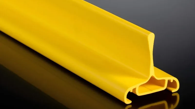
In profile extrusion, the die head shapes the melt, but the vacuum calibration tank decides whether that shape survives contact with reality. The extruded profile leaving the die is a hot, nearly liquid section: one step of die swell away from oversize and one stretch of haul-off tension away from undersize. Everything that happens in the following four to twelve metres of tank determines the dimensions the customer actually measures.
This article walks through how vacuum sizing works, how much vacuum a section really needs, how cooling length and water temperature interact with line speed, and how to trace common defects back to the tank. For the wider process context — materials, die design and line layout — start with the plastic extrusion molding overview.
- The calibration tank, not the die, fixes the final outer dimensions of an extruded profile; the die only delivers a deliberately oversize melt.
- Vacuum should be zoned: highest in the first chamber against the calibration sleeve, then stepped down downstream to protect the surface.
- Typical applied vacuum for rigid sections falls between roughly 0.2 and 0.7 bar, tuned to wall thickness, section geometry and material.
- Cooling length matters as residence time — length divided by line speed — and residence time is the variable to control, not tank length alone.
- Waviness, bow, corner collapse and drag marks usually trace to vacuum distribution or water temperature before they trace to the die.
- Dimensional stability should be verified over a continuous run of 30–60 minutes, not from a single first article.
What Does a Vacuum Calibration Tank Do in Profile Extrusion?
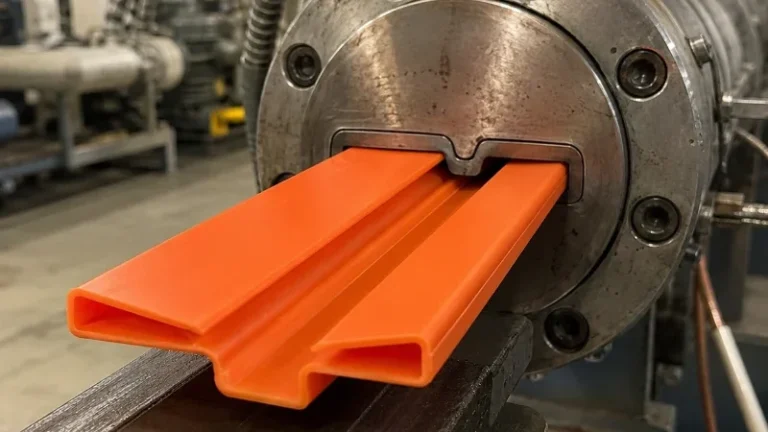
A vacuum calibration tank sizes and cools the hot profile immediately after it leaves the die head. Vacuum pulls the soft outer surface against a water-cooled calibration sleeve1 or a set of calibration plates, fixing the outer geometry while circulating water removes heat, so the section solidifies at target dimensions.
The physics are unforgiving. At the die exit, rigid PVC melt sits somewhere around 180–210 °C depending on formulation and screw design, and a hollow section has no stiffness at all. Below the die, gravity and haul-off tension both act on the melt. Without a sizing system, the outer contour would be defined only by die swell and draw-down2 — neither of which a production drawing can be quoted against.
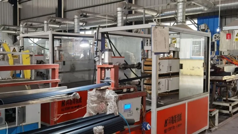
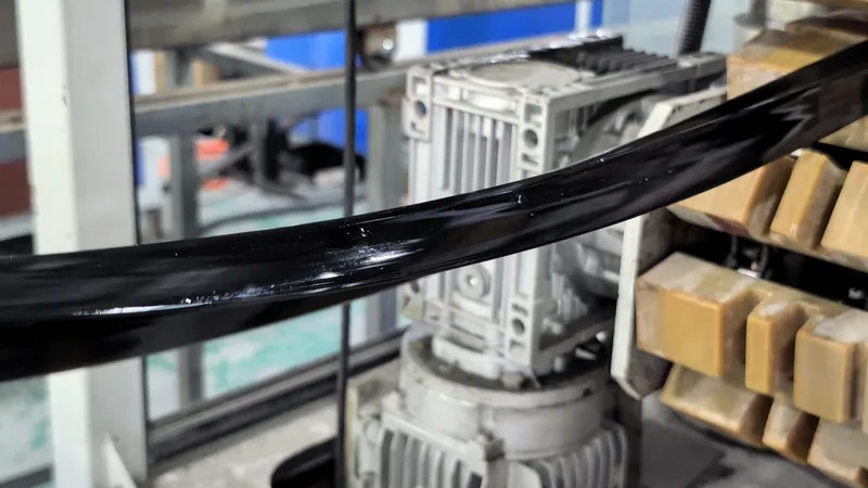
Inside the tank, the profile passes through one or more calibration sleeves or floating plate sets. Vacuum chambers behind the sleeve draw air and water out through slot or hole patterns, pressing the profile outward against the metal. Cooling water flows over — and in wet systems, through — the section, while support rollers keep the part aligned until it is stiff enough for the haul-off and any downstream in-line punching or printing.
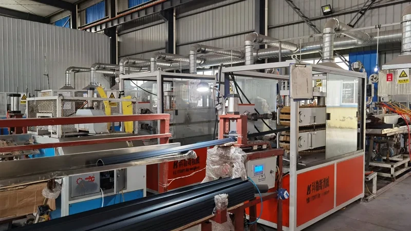
ZetarVac runs 7+ automated extrusion lines with a maximum profile width of 600 mm and up to three-layer co-extrusion in a single pass. At those widths and layer counts, calibration is where a drawing tolerance either holds or quietly drifts: the die head gets the melt close, and the tank closes the gap.
How Does the Die Head Work with the Calibration Sleeve?
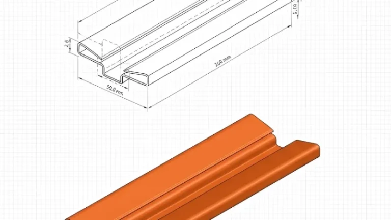
The die head meters the melt and defines the flow geometry; the calibration sleeve defines the final outer dimensions. The die gap is cut oversize to compensate for die swell and draw-down, and vacuum holes in the sleeve pull the melt onto the metal so the extruded profile leaves the tank at drawing size.
Die swell is the starting point. When the melt leaves the die head, it expands as molecular orientation relaxes — a few percent for most rigid compounds, more for soft formulations. The extrusion die and the sleeve are therefore designed as a pair: the sleeve contour, its vacuum hole layout and the expected draw-down all come from the same section calculation. Treating them as separate purchases is a common way to lose a tolerance.
For hollow sections with internal webs — a drainage channel or a multi-cavity profile — dry sleeve calibration is usually the first choice, because the outer walls must be fixed before the webs have fully set. For open or semi-open sections, plate calibration inside a wet vacuum tank is more forgiving and easier to adjust on the line. Co-extrusion3 adds a further constraint: when a rigid ABS core runs with a soft TPU lip, as in a robot-vacuum squeegee strip, first-chamber vacuum has to be gentle enough not to distort the soft layer while still setting the rigid part.
| Aspect | Dry sleeve calibration | Wet plate calibration |
|---|---|---|
| Dimensional fixing | Strongest; outer walls set before water contact | Moderate; plates guide the section in water |
| Cooling intensity | Limited at entry; water film only | High; full water contact along the tank |
| Surface finish | Best control of gloss and edge sharpness | Risk of water marks on glossy faces |
| Adjustment | Sleeve is section-specific with fixed geometry | Plate position and vacuum adjustable on the line |
| Typical use | Tight-tolerance and hollow sections | Open sections and higher line speeds |
Many lines combine the two: a short dry sleeve at entry, then plates in the same tank, pairing firm sizing with high cooling efficiency. That combination — not the die alone — is what makes a tight cross-section tolerance realistic on a production line.
How Much Vacuum Does an Extruded Profile Need?
Most rigid sections run between roughly 0.2 and 0.7 bar of applied vacuum, with the highest reading in the first chamber right after the sleeve and lower settings downstream. The correct value depends on wall thickness, section stiffness, material and water temperature, and it is tuned on the line rather than on paper.
Thin walls and sharp corners need more vacuum, because there is less material to hold the shape while the outer skin sets. Thick or solid sections need less, and excessive vacuum on them mainly increases friction against the sleeve. A practical starting pattern is a high first chamber, tapering through the second and third, with the last chambers running just enough vacuum to keep the section in contact with its supports.
For PVC-U4 window and door profiles, EN 12608 specifies the profile geometry, impact resistance and heat reversion the finished part must meet — three properties that all depend on how completely the section was fixed and cooled before it left the tank. Compound selection matters as well: ASTM D1784 classifies rigid PVC and CPVC compounds by cell class, and a stiffer, higher-impact compound tolerates a different vacuum window than a general-purpose one.
"Turning the vacuum up always improves dimensional accuracy."False
Excess vacuum drags soft melt against the sleeve, producing drag marks, gloss loss and frozen-in wall stress. The profile can measure to size at the tank exit and still bow or twist after it cools on the rack.
"Vacuum should be zoned and tuned to the section geometry."True
A high first chamber sets the outer walls while the melt is soft; lower downstream settings hold contact without friction. That distribution delivers stable dimensions and an undamaged surface, which a single high setpoint cannot achieve at the same line speed.
Cooling Length, Water Temperature and Haul-off Speed
Residence time is the real variable. Cooling length only matters as length divided by line speed: a 6 m tank at 1.5 m/min gives the same residence as a 9 m tank at 2.25 m/min. As sizing ranges, small rigid sections typically run in 4–6 m tanks, hollow window-style sections in 6–9 m, and thick-wall or multi-layer sections may need 10–12 m or a second tank in series. These ranges shift with material and line speed, so treat them as starting points rather than guarantees.
Water temperature is the quieter lever. Rigid PVC is often started in warmer water — well below melt temperature but above ambient — so the outer skin sets gradually enough to avoid freezing in stresses and gloss defects, while downstream zones drop toward ambient for bulk cooling. Whatever the route, the profile should leave the tank well below its Vicat softening temperature5; ISO 306 defines that value as a heat-resistance indicator, and a profile exiting near it keeps shrinking and distorting after the tank.
Haul-off speed closes the loop. Raising speed without adding cooling capacity shortens residence time, and the first symptom is usually a profile that measures correct at the tank and swells or bows after exit. Dual-belt haul-offs grip wide or delicate sections without crushing them, but belt pressure adds its own distortion if the section is still soft. Downstream in-line punching and embossing demand a profile that is dimensionally settled and cool enough to hold a hole position.
Which Defects Trace Back to the Calibration Tank?
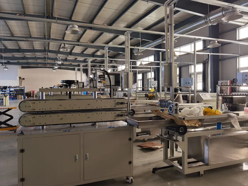
Most post-die defects — waviness, bow, twist, corner collapse and drag marks — point to the tank before the die. A profile that left the die head correct can be pushed out of shape within the first metre of cooling by uneven vacuum, wrong water temperature or a worn sleeve.
The fastest diagnosis path is to change one variable at a time and measure at fixed intervals — for example at 10, 30 and 60 minutes of continuous running — because several of these defects look identical under a caliper and differ only in how they develop over time.
| Symptom | Likely calibration cause | First correction |
|---|---|---|
| Waviness on flat faces | Vacuum too high in later chambers; loose section contact | Reduce downstream vacuum; check sleeve or plate fit |
| Corner collapse or oversize corners | Insufficient entry-chamber vacuum; blocked vacuum holes | Raise first-chamber vacuum; clean the hole pattern |
| Longitudinal bow or twist | Uneven cooling across the section | Balance water flow; check side cooling and support alignment |
| Drag marks or gloss patches | Melt dragged along a dry sleeve; entry vacuum too high | Lower entry vacuum; increase the water film at the sleeve |
| Swelling or bow after exit | Profile leaves the tank too hot | Lengthen the tank, reduce line speed or lower downstream water temperature |
Two of these failure modes deserve closer attention because they are routinely misread when buyers compare suppliers and judge whether a process is genuinely stable.
"Passing first-article inspection proves the tank setup is production-ready."False
A single sample is measured while the process has only partly stabilized, and it says nothing about drift. As water temperature and vacuum pump load settle over the first hour, dimensions move — and the move shows up later as scrap, not as a report.
"Dimensional capability must be verified over a continuous run."True
Measuring at fixed intervals across 30–60 minutes of running captures thermal drift, pump behavior and early sleeve wear. Only that trend shows whether the calibration setup will hold tolerance across a full production shift.
How Do You Size and Specify a Tank for a New Profile?
Work from the section drawing outward: wall thickness sets the cooling time, cooling time and target line speed set the tank length, and the geometry decides the sleeve or plate configuration. Specify vacuum capacity, chamber count and water flow against that line speed, not against a tank catalogue.
A practical specification checklist covers tank length and chamber count; vacuum pump capacity and the number of independently adjustable zones; water flow, filtration and temperature control per zone; three-dimensional adjustment of the calibration tooling for fast changeover; and easy access for cleaning vacuum holes, which block more often than any engineer admits. For hollow sections, confirm the tank accepts a full-length dry sleeve followed by downstream plates.
Section-specific tooling is the part buyers underestimate. One tank serves many profiles, but every new section needs its own sleeve or plate set, and alignment time on the line is what separates a smooth changeover from a lost shift. Running a DFM check on the profile and die design before tooling is cut avoids most of these surprises, and the custom profile extrusion capabilities overview shows how die, sleeve and tank are specified as one system.
ZetarVac develops non-standard profile sections to customer drawings and supports prototyping, small batch and large batch production. Because the die head, calibration tooling and tank setup are engineered from the same drawing, tolerance discussions can start before tooling is cut rather than after the first parts come out wrong.
FAQ
How long should a vacuum calibration tank be for a PVC profile?
Small rigid sections typically run in 4–6 m tanks, hollow window-style profiles in 6–9 m, and thick-wall or multi-layer sections in 10–12 m or two tanks in series. The governing calculation is cooling time multiplied by line speed, with margin for seasonal water temperature changes.
What vacuum level should be used for rigid PVC profiles?
Start with roughly 0.4–0.7 bar in the first chamber for hollow rigid PVC sections, tapering downstream; solid or thick sections often run lower. Treat these as starting points — wall thickness, compound stiffness and water temperature all shift the window, and final settings are tuned on the line.
Can one calibration tank serve several different profiles?
The tank can; the tooling cannot. Each section needs its own calibration sleeve or plate set cut to that contour. What a well-specified tank adds is fast, repeatable three-dimensional adjustment, so changeovers between sections take minutes rather than shifts.
Why does a profile pass inspection but drift out of tolerance later?
Water temperature, vacuum pump load and sleeve condition all drift over the first hour of running. A profile measured once at start-up reflects that moment only. Record dimensions at fixed intervals over a continuous run to see whether the setup is genuinely stable.
Does higher line speed always require a longer tank?
Usually, because residence time is length divided by speed. The alternatives — higher vacuum, colder water or stronger calibration tooling — all carry trade-offs in surface quality and residual stress. For a stable process, cooling capacity should grow in proportion to any speed increase.
If you are weighing calibration and cooling options for a new section, send your drawings and target line speed so an engineer can review the sizing and cooling setup with you — the ZetarVac plastic extrusion manufacturer page is the direct route, and you can also compare the full service scope during supplier selection.
-
Calibration sleeve: A water-cooled metal sleeve with vacuum ports at the tank entry that fixes the outer dimensions of a hot profile by holding it against the inner contour while the surface sets. ↩
-
Draw-down ratio: The ratio between the die opening cross-section and the finished profile cross-section; it describes how much the melt is stretched by haul-off after the die. ↩
-
Co-extrusion: Extruding two or more materials through one die head to form a single profile with distinct layers, such as a rigid core with a soft sealing lip. ↩
-
PVC-U: Unplasticized polyvinyl chloride — rigid PVC without plasticizers, the standard compound for window, door and construction profiles. ↩
-
Vicat softening temperature: The temperature at which a loaded flat needle penetrates a thermoplastic specimen to a defined depth, defined in ISO 306 as a heat-resistance indicator. ↩