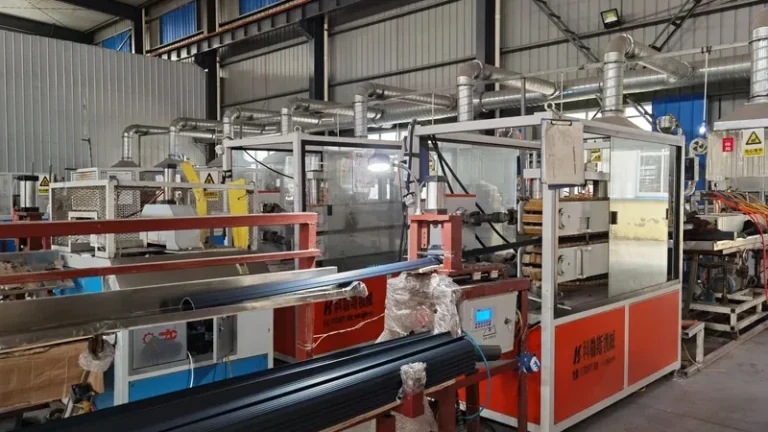
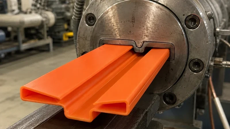
In plastic extrusion, every decision made upstream — resin choice, screw speed, melt temperature — converges on a single component: the die. If the die is wrong, no downstream adjustment will rescue the profile; if it is right, the line can run for weeks with stable dimensions. This guide explains what a die actually does in the extrusion process, how a die head turns pressurized melt into an extruded profile, and which design factors deserve scrutiny before you commit to tooling. For the wider process context, see the plastic extrusion molding guide.
- The die is the precision-machined component at the end of the extruder that shapes pressurized polymer melt into a continuous profile cross-section.
- Die head flow design, land length, and drawdown ratio together determine dimensional accuracy, surface quality, and long-run stability.
- Polymer melt swells as it exits the die, so the opening is deliberately cut larger than the finished profile.
- Multi-layer co-extrusion dies feed two or three materials into one profile, combining rigid structure with soft functional surfaces.
- First-article approval does not guarantee production stability; tolerance capability must be proven over a sustained run.
- Judge die quotations against total profile cost — scrap, changeover time, and tooling life — not tooling price alone.
What Exactly Is a Die in Plastic Extrusion?
A die in plastic extrusion is the precision-machined metal component at the discharge end of the extruder that converts pressurized, molten polymer into a continuous cross-section of fixed shape. Because it is the last thing the melt passes through before cooling and sizing, the die’s internal geometry largely defines the profile’s final dimensions, surface quality, and layer structure.
The die never works alone. Upstream, the extruder screw melts and pressurizes the polymer, while a screen pack and breaker plate filter contaminants and build the back pressure that homogenizes the melt. The melt then flows through an adaptor into the die head, where a balanced flow channel distributes it evenly across the full width of the opening. Downstream, a vacuum calibrator, cooling tank, and puller fix the shape the die only roughly delivers. The die is one stage in a pressure–temperature–geometry chain, and quoting it in isolation hides half the engineering.
In practice, three terms describe different parts of this tooling. The die head is the complete assembly bolted to the extruder, including the flow distributor and retaining hardware. The die itself is the final calibrated opening that shapes the profile. In co-extrusion, separate feed blocks join additional melt streams before the common exit. Suppliers use these terms loosely in quotations, so confirm exactly what is included — distributor, land section, calibrator, and downstream sizing — before comparing prices.
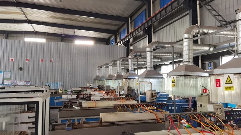
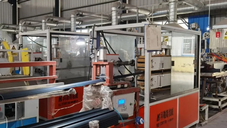
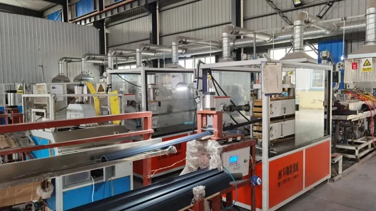
ZetarVac runs more than 7 automated extrusion lines with a maximum profile width of 600 mm, so die design and line capability are matched within one plant: a profile designed around a 500 mm cross-section will never be quoted to a line that cannot physically carry it. Buyers should review the die and the production line together rather than as separate assumptions.
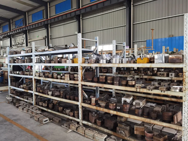
For a custom profile, the die is usually the largest upfront investment and the longest-lead item in the project. A sound die reduces scrap for the life of the product; a marginal one converts every material lot change and every shift change into a quality risk. Understanding what happens inside it is therefore a procurement skill, not just a design detail.
How Does the Die Head Turn Melt Into an Extruded Profile?
Inside the die head, a flow distributor spreads polymer melt from the round adaptor bore into the full cross-section of the profile at uniform velocity and temperature across the entire exit. The shaped land that follows stabilizes the flow, and the melt leaves as a continuous ribbon that is then sized, cooled, and pulled to final dimensions.
The distributor is the hardest part of the design. Coat-hanger and fishtail channel geometries gradually widen the round melt stream into the profile outline while keeping path length and flow resistance equal to every point of the exit. Where resistance is unequal, the melt exits faster in some regions than others, producing thick and thin zones the calibrator cannot fully correct. Internal webs and mandrels that form hollow sections add a further constraint: they split the flow, and the streams must rejoin cleanly behind them without leaving weak weld lines.
Straight dies do not cut the product to size. Thermoplastic melt is viscoelastic: compressed inside the die, it relaxes and expands the moment pressure is released — the effect known as die swell1. A rigid PVC profile may exit noticeably larger than the die opening, with the amount depending on melt temperature, exit shear rate, and the elastic character of the resin. Designers compensate in two ways: the opening is cut oversize, and the haul-off deliberately stretches the melt — the drawdown ratio2 — pulling it toward final dimension. Getting either number wrong shows up as waviness, bow, or wall-thickness drift hours into a run, not in the first sample.
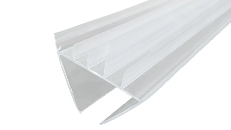
Downstream of the die, a vacuum sizing sleeve and water cooling fix the dimensions the die approximately delivers, and this tooling belongs in the same quotation as the die head. The flow channel decisions behind this stage are covered in detail in the extrusion die head design guide.
Which Die Design Factors Control Profile Tolerances?
Four die-side factors dominate profile tolerance: how uniformly the flow channel delivers melt to every point of the exit, how long the land stabilizes the flow, how much the melt swells after exit, and how the downstream sizing corrects what remains. Tight tolerances are won or lost at the die head long before the calibrator can adjust anything.
The land3 is the final parallel section of the flow channel, and its length is a compromise. A longer land smooths the melt and steadies exit velocity, improving surface gloss and dimensional consistency, but it also raises back pressure and the risk of stagnation and degradation in heat-sensitive resins such as rigid PVC. As a common engineering range, land length falls between roughly one-fifth and the full equivalent wall thickness of the profile, adjusted per material and section geometry. An incorrectly proportioned land produces exactly the defects buyers see later: flow lines, uneven walls, or intermittent surface roughness.
Material choice shapes the die as much as geometry does. For rigid PVC window and door profiles, EN 12608 specifies the profile geometry, impact resistance, and heat reversion requirements that the extruded product must meet, which in turn dictates how much post-die sizing the tooling package must provide. Compound classification matters as well: ASTM D1784 classifies rigid PVC and CPVC compounds by cell class, and the specified cell class determines melt stiffness, so the same die geometry will not behave identically on two different compounds. Fixing the material designation early lets the die designer tune the channel and land for that specific resin instead of a generic compromise.
| Material | Typical profile applications | Die and processing considerations |
|---|---|---|
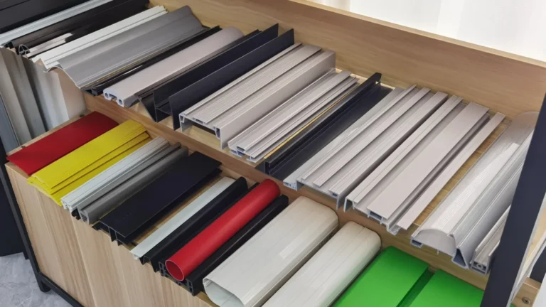
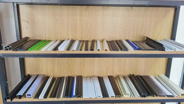
| PVC (rigid) | Window and door profiles, decorative trims, pipes, sealing strips | Heat-sensitive melt; moderate land length to limit residence time; pronounced post-exit swell |
| ABS | Automotive and industrial profiles, decorative parts | Good flow balance; moisture control strongly affects surface quality |
| HDPE | Pipes, edge trims, guide rails, wear strips | High shrinkage and swell; sizing sleeve must be cut accordingly |
| PC / PMMA | Transparent pipes, light covers, clear profiles | Optically critical: polished channels and strict temperature control to avoid die lines |
| TPE / TPV | Sealing strips, gaskets, soft profiles, automotive seals | Soft elastic melt; drawdown control holds lip and seal dimensions |
Defects that originate at the die — flow lines, melt fracture, uneven walls — are diagnosed systematically in the extrusion defects troubleshooting guide. A die supplier who can explain root causes in these terms is worth more than one who simply re-cuts the opening and hopes.
"If the first article matches the drawing, the profile will hold that tolerance for the whole production run."False
A first article reflects one short window of one operating condition. Melt temperature drift, die wear, and compound lot changes all shift dimensions over hours of continuous running, so a start-up sample proves very little about week-two stability.
"Tolerance capability should be demonstrated over a sustained run, not by a single sample."True
A meaningful capability check measures the profile across several hours or a full shift, tracking wall thickness and critical cross-section dimensions against the drawing. Only that data shows whether the die, the calibration, and the control loop are genuinely in balance.
When comparing quotations, ask how each supplier intends to prove this capability and what happens if the sustained run drifts — die re-cut, calibrator change, or process re-tuning. The answer tells you how much of that risk stays with the supplier and how much quietly moves onto your side of the table.
What Happens Inside a Multi-Layer Co-Extrusion Die Head?
In a co-extrusion die head4, two or three polymer melt streams travel through separate channels and merge into a single layered profile at or near the common exit, so each layer keeps its own material properties within one continuous cross-section.
Each stream needs its own balance. The rigid layer — often PVC, ABS, or PP — carries structure and must fill the outer walls evenly; the soft layer — TPE, TPU, or TPV — forms gaskets, sealing lips, or wear surfaces and is far more sensitive to shear and temperature. The die head designer controls layer thickness through channel geometry and flow restrictors, and interface stability depends on matched melt viscosities at the merge point. If one stream arrives too hot or too fast, it wraps or thins the other layer unpredictably, which is why co-extrusion dies are tuned per material pair rather than sold as universal tooling.

ZetarVac co-extrudes up to three layers in a single pass, with combinations actually in production including PP+TPV, PP+TPE, PVC+TPU, ABS+TPU, and TPV+CPVC. The layer structure therefore does not have to be compromised to fit the tooling: the die head is built around the material pair and the functional requirement instead.
Two production examples show why this matters. An automotive seat slide rail strip extruded in PP+TPV combines dust exclusion, guiding, wear resistance, and low friction from the TPV sealing lip with structural support from the PP body — a function no single material delivers. A household robot vacuum squeegee strip in ABS+TPU uses the rigid ABS core for support and the flexible TPU outer layer for wiping contact that survives constant abrasion. In both cases, the value is created at the die head, where the layers meet.
"A cheaper die always means a lower total cost for the extruded profile."False
Tooling price is a one-off; the profile is paid for by the tonne. A die that runs slower, produces more scrap, or needs frequent cleaning can cost far more over a year than the purchase savings, especially on continuous multi-shift production.
"Die value should be judged against scrap rate, changeover time, and tooling life."True
A die that holds dimension through long runs, cleans down quickly between material changes, and survives re-polishing delivers a lower cost per kilogram of finished profile. Ask suppliers to estimate these factors at your expected volume, not just the tooling price.
The channel design behind multi-layer merging is examined further in the co-extrusion die head guide for multi-layer profiles, including how feed block layout affects layer thickness control.
Reviewing a Die Quotation and the First-Article Run
A die quotation is only as good as the information behind it. At minimum, the supplier needs the cross-section drawing with dimensions and critical tolerances, the material designation, the layer structure for co-extrusion, expected annual volume, and any post-extrusion operations. In return, a serious quotation states what is included — die head, calibrator, and downstream tooling — the guaranteed tolerance on specific dimensions, the acceptance procedure for the first article, and the delivery basis for the tooling. Ambiguity in any of these items is where cost overruns and schedule slips begin.
Secondary operations deserve early attention. Punching, embossing, and printing are performed in line on ZetarVac’s extrusion lines, which means holes, surface textures, and markings are integrated into the continuous process rather than added in a separate stage. Deciding this at the design stage changes the tooling package: an in-line punching station needs positional accuracy from the puller and cooling system, and embossing rollers become part of the die-side tooling. With reference monthly capacity of roughly 300–500 tonnes across the extrusion lines, prototype batches and volume production run on the same class of equipment, so first-article settings translate directly into series settings.
Across the plant, 45+ production lines operate in total, spanning single-layer, double-layer, and triple-layer extrusion as well as foam extrusion. The practical consequence for buyers is that a profile does not have to wait for a dedicated line: the die is designed for the section and material, then matched to whichever line class fits the volume and cross-section.
Finally, ask about the die’s working life. Extrusion dies are re-usable assets: with correct cleaning, storage, and periodic re-polishing of the flow channel, a die serves multiple campaigns over years. Die storage and maintenance practice is therefore part of your quality system, not just the supplier’s — a die that sits corroded between runs will hand surface defects straight into your next production batch.
FAQ
How long does an extrusion die last?
With proper maintenance, an extrusion die is long-life tooling rather than a consumable. The flow channel and land are hardened, precision-ground steel, and wear concentrates where melt velocity is highest. Periodic cleaning, inspection, and re-polishing keep dimensions stable across many campaigns. What shortens life most is degraded resin left to carbonize in the channel and damage to the polished exit face during handling or storage.
Can one die produce several different profile sizes?
Generally no. A die is cut for one cross-section and one drawdown window, so a new profile shape means new tooling. What one die can do is produce the same profile across a small range of wall thicknesses or widths if the sizing and puller allow the adjustment. Family tooling with interchangeable land inserts exists, but it trades flexibility against flow balance and only makes sense for genuinely similar sections.
What information is needed to quote a custom extrusion die?
Provide the cross-section drawing with critical dimensions and tolerances, the material designation, the layer structure if co-extrusion is involved, target annual volume, and any in-line operations such as punching or embossing. With these inputs, a supplier can quote the die head, calibrator, and downstream tooling as one package and state which tolerances are realistic. Drawings that omit material or tolerance intent force the supplier to guess, and the guess reappears later as re-cutting cost.
What tolerance can an extruded profile realistically hold?
It depends on material and section geometry. As a reference point, ZetarVac achieves a minimum dimensional tolerance of ±0.05 mm on the profile cross-section, subject to those same constraints. Simple open sections in rigid PVC hold tighter than large hollow sections in polyolefins, where shrinkage and swell dominate. The practical step is to mark which dimensions are functionally critical and let the die design protect those specifically.
Where should a buyer start when evaluating die options?
Start with the drawing, not the price list. Mark the critical dimensions and confirm the material, then send your drawings to the ZetarVac engineering team for review or talk to an engineer about your application. A structured review covering tolerance capability, layer structure, and downstream operations is the most reliable way to compare your current die design against a supplier’s capability before committing to tooling.
-
Die swell: the expansion of viscoelastic polymer melt as it exits the die and relaxes the elastic deformation stored inside the flow channel. ↩
-
Drawdown ratio: the relationship between the die opening cross-section and the finished profile size, set by haul-off speed relative to melt exit speed. ↩
-
Die land: the final parallel section of the die flow channel that stabilizes melt flow and defines the exit geometry before the profile is drawn and cooled. ↩
-
Co-extrusion: an extrusion process in which two or more polymer melt streams merge into a single layered profile through one common die head. ↩