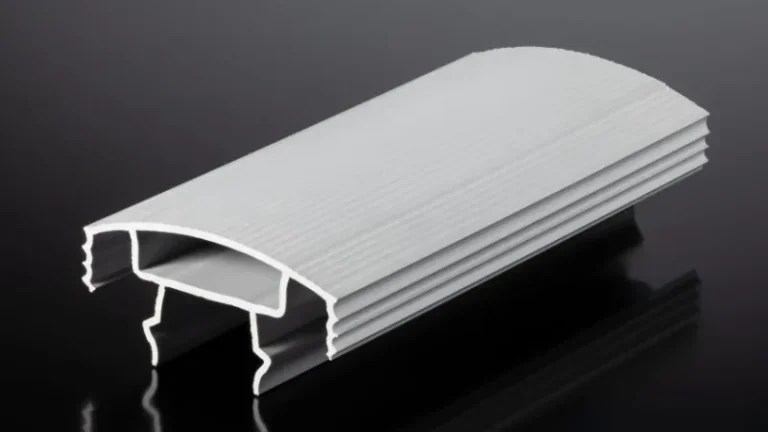
Choosing a custom plastic profile extrusion manufacturer is an engineering decision long before it is a purchasing one. Any supplier can send a polished sample; far fewer can hold your cross-section within tolerance for an eight-hour run, across resin batches, with different operators on each shift. This guide sets out the checks — line hardware, material grades, die and calibration control, tolerance practice, and repeatability evidence — that separate a genuine profile extrusion partner from a price list with a logo.
The same logic applies whether you are buying window profiles, cable channels, guide rails, wear strips, or a co-extruded section with a soft sealing lip. Markets differ — building, automotive, industrial, medical, logistics, agriculture, consumer — but the questions you put to a supplier do not. Ask them in this order.
- Judge capability by the whole line — extrusion die, calibrator, haul-off, and cooling — not by sample parts alone.
- Match material grades to the service environment before tooling; a supplier’s grade list shows what the plant actually runs.
- A committed cross-section tolerance of ±0.05 mm is credible; anything dramatically tighter deserves hard questions about measurement.
- Treat first-article approval as a starting point, and gate volume release on repeatability across shifts and batches.
- Co-extrusion of up to three layers adds function but also a second melt stream to balance, so ask for pairing evidence.
- Put tolerance, sampling, and change-control rules in writing before any volume commitment.
What separates a real profile extrusion manufacturer from a broker?
A genuine manufacturer owns its extrusion lines, controls die design and maintenance, and can show process data from a running line. A broker forwards your drawing elsewhere and adds margin without adding process knowledge. Ask directly who runs the line, who owns the die, and who answers when a dimension drifts mid-run.
Plant scale is a useful signal, though it should be read carefully. What matters is not total floor area but whether the extrusion side has dedicated lines, experienced die makers, and a material library the plant actually processes. A shop that runs PVC window profiles one week and TPV automotive seals the next has met more failure modes than one running a single commodity shape all year.
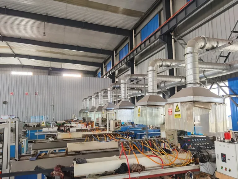
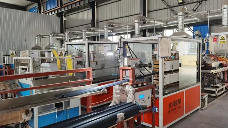
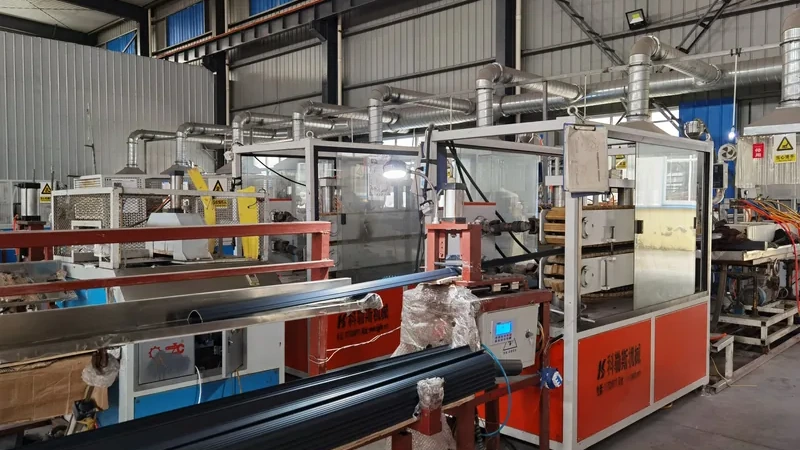
ZetarVac operates 7+ automated extrusion lines inside a plant of 45+ production lines, with reference monthly capacity of roughly 300–500 tonnes across the extrusion lines. For a buyer, that reads less as a headline number and more as evidence that profile extrusion is a core discipline with room for your program.
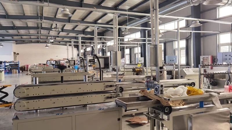
For a first pass, audit the line hardware rather than the website. Width range tells you whether your section even fits: lines that handle profile widths from 5 to 600 mm cover everything from small sealing strips to wide panel trims. Also ask whether the line supports in-line punching, embossing, or printing, because secondary operations performed while the profile is still moving avoid a whole class of handling damage.
Finally, test responsiveness with a small question before a large order. Send one drawing detail and ask how the die head would be vented, cooled, or adjusted for it. A manufacturer that answers with process reasoning within days is showing you the same behavior you will get at hour six of a production crisis.
Which material grades and standards should shape your specification?
Start from the service environment, not from a resin datasheet. The strongest specifications name a material family, a grade intent, and the standards that grade must satisfy, because the grade list a supplier actually runs is the clearest map of what it can hold in production.
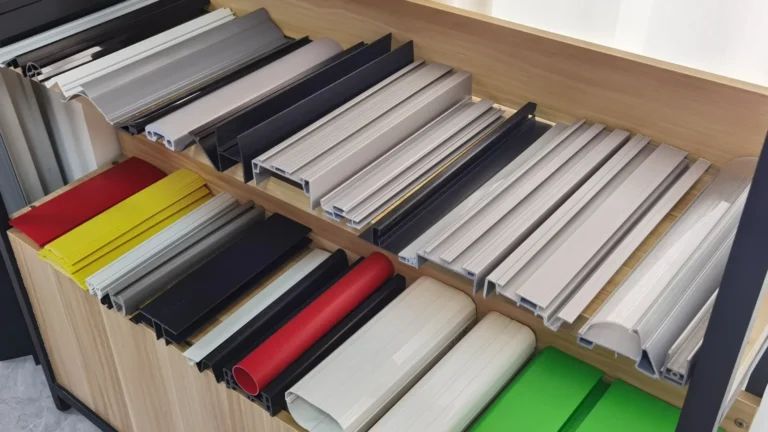
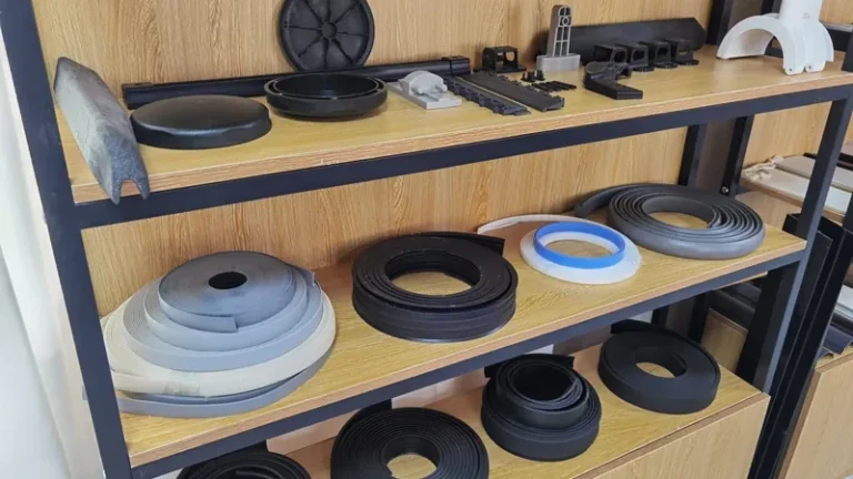
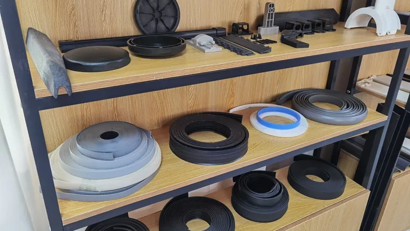
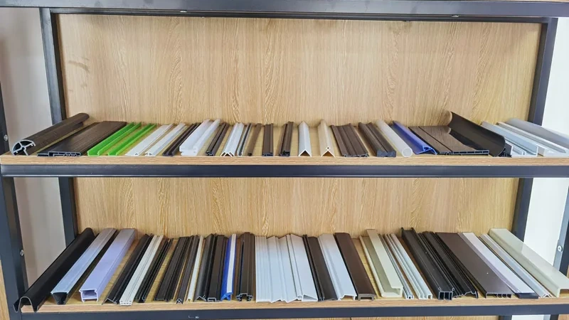
A capable extruder should be fluent across material families rather than married to one. A working library typically includes PVC for window and door profiles, decorative trims, pipes, and sealing strips; ABS for automotive and industrial profiles; HDPE for pipes, edge trims, guide rails, and wear strips; PP for functional parts; PC and PMMA for transparent pipes and light covers; PA6 and PA66 for wear and mechanical parts; POM for precision guides; TPE, TPV, and TPU for seals and soft layers; ASA for outdoor exposure; and PP/GF for high-strength structural sections.
| Material family | Typical extruded profiles | Watch-outs |
|---|---|---|
| PVC | Window and door profiles, trims, pipes, sealing strips | Heat reversion and impact resistance checks apply |
| HDPE | Pipes, edge trims, guide rails, wear strips | Higher shrinkage; measure after full cooling |
| PP | Profiles, pipes, functional parts | Sensitive to melt temperature swings |
| PC / PMMA | Transparent pipes, light covers, clear profiles | Optical clarity needs clean melt and gentle cooling |
| PA6 / PA66 / POM | Precision guides, wear and mechanical parts | Moisture control dominates dimensional stability |
| TPE / TPV / TPU | Seals, soft lips, gaskets, buffer parts | Co-extrusion bonding depends on pairing history |
| ASA | Outdoor and building profiles | Request weathering data for long exposure |
Standards give the specification teeth. For PVC-U window and door profiles, EN 12608 is the European standard that fixes requirements for profile geometry, impact resistance, and heat reversion, so a supplier quoting these parts should reference it unprompted. For mechanical data, ASTM D638 defines the standard tensile test used to report strength and elongation of plastics, and it is the default citation to expect on any datasheet for extruded profiles. Where flame behavior matters in appliances or electronics, UL 94 classifies the flammability of plastic materials and should appear next to the material callout.
Two practical checks follow. First, ask how melt flow1 is verified at incoming inspection, since two lots of one nominal grade can behave differently at the die. Second, ask which grades the plant has actually co-extruded, because a rigid core with a soft sealing lip is a different skill from a mono-material section, and pairing history predicts success better than a brochure.
How do the extrusion die and calibration stage expose real capability?
The extrusion die shapes the melt, but the calibrator, vacuum, cooling, and haul-off decide whether that shape survives. A capable supplier can explain die swell compensation, calibration length, and cooling balance for your specific section in numbers, not generalities.
Melt leaving the die head swells as elastic stresses relax, so die openings are deliberately cut smaller than the final profile. Correcting for die swell2 is a learned skill: the correction depends on material, melt temperature, and line speed, and it changes with every section family. Ask a prospective supplier how they compensate swell on a section like yours, because vague answers here predict vague dimensions later.
Downstream, calibration is where the profile is fixed. Sizing sleeves, vacuum levels, and water temperature work together, and the haul-off3 must pull in sync with melt delivery. When pull speed and extrusion output drift apart, width and wall thickness drift with them, which is why serious lines pair calibrated pullers with closed-loop feedback rather than manual knobs alone.
For multi-layer sections, the co-extrusion block adds another set of variables: each layer has its own melt stream, temperature, and pressure, and the layers must bond at the right thickness ratio. Pairing history, again, is the evidence to request.
ZetarVac runs single, double, and triple-layer co-extrusion in one pass, with working combinations that include PP+TPV, PP+TPE, PVC+TPU, ABS+TPU, and TPV+CPVC. If your profile needs a rigid body with a flexible sealing or wiping layer, ask for samples from a similar pairing rather than accepting a generic yes.
What tolerance and repeatability evidence should you demand?
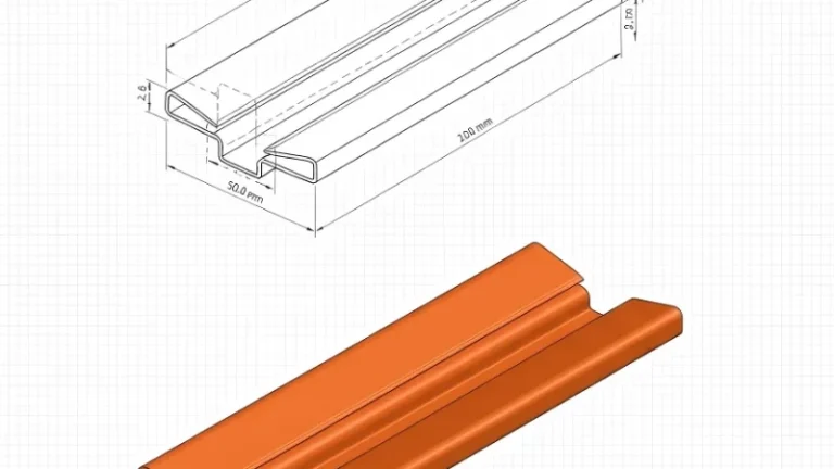
Plan around roughly ±0.05 mm on the profile cross-section as a realistic minimum for custom extruded profiles, subject to material and section geometry. More important than the number is the measurement practice behind it: fixed fixtures, defined datums, and an agreed sampling frequency.
Tolerance talks should separate critical from cosmetic features. Mounting faces, sealing lips, and slide channels need tight control; broad decorative surfaces usually do not. Over-tolerancing every dimension raises tooling and inspection cost without adding function, so define datums and critical features before the die is cut, and pressure-test the drawing with a DFM checklist for extruded plastic profiles and extrusion dies before committing steel.
"The tighter the tolerance a supplier quotes, the better the extrusion manufacturer."False
A quote far beyond ±0.05 mm on a complex cross-section usually signals inexperience, not precision, because shrinkage, die swell, and calibration physics set the real limits. Accepting it invites disputes when production dimensions land where physics says they must.
"About ±0.05 mm on the profile cross-section is a realistic committed tolerance."True
That figure matches what a disciplined extrusion plant can hold across materials and section geometries. Treat it as a comparison baseline, then tighten only on the few features your assembly genuinely needs.
Then ask how the plant verifies dimensions: which gauge, which fixture, how often, and what happens when a trend moves rather than a single part fails. Repeatability evidence closes the loop. Request trend charts from a comparable run showing dimension versus time across shift changes and at least one resin batch change; a stable band indicates a controlled process, while a staircase indicates luck. Indices such as Cpk4 summarize capability in one number, but ask for the underlying chart too.
Punching, embossing, and printing run in-line on ZetarVac’s extrusion lines, so secondary features are formed while the profile is still inside the controlled process. Off-line machining after cooling adds handling marks, extra fixturing, and another tolerance stack, which is worth avoiding where the design allows.
Can a first-article sample predict stable production runs?
No. A first article confirms geometry direction, color, and surface quality at one point in time. Production stability only appears in trend data across hours, batches, and shifts, so first-article approval should open the pilot phase, not close the project.
Structure qualification as three gates: a pilot run at moderate throughput, a sustained run at target speed, and a hold test at the top of the planned duty cycle. Each gate needs written pass criteria — dimensional band, defect rate, appearance standard — and a named owner for corrective action. Jumping from first article to full volume is the most common way buyers end up negotiating quality claims mid-program.
During the pilot, watch how the supplier responds to variation rather than whether variation exists. Every extrusion line drifts; the question is whether the response is a documented adjustment ladder or improvised knob-turning. Suppliers who log melt temperature, vacuum, and pull-speed changes against measured dimensions recover faster and argue less.
"Once first-article approval is signed, production risk is behind you."False
First articles are short, closely attended runs under hand-picked conditions. Sustained production adds batch variation, thermal drift, and shift-to-shift differences that no single sample represents, so risk reappears exactly when volume and visibility are highest.
"Repeatability across shifts and resin batches is the real stability test."True
A process that holds its dimensional band through batch changes and shift handovers has demonstrated the control loop buyers actually pay for. Gate volume release on that evidence, not on the sample that won the project.
One more gate deserves attention: change control. Agree in writing what happens when a material grade, colorant, or additive changes, because even small formulation shifts alter cooling behavior and dimensional balance. A one-page requalification rule prevents months of quiet drift and keeps later audits short.
FAQ
What should an RFQ for custom profile extrusion contain?
Include the section drawing with critical dimensions and datums, material family and grade intent, expected annual volume, service environment, and any co-extrusion layer requirement. Attach tolerance priorities so the supplier prices measurement effort correctly rather than just material. For a fuller template, see the guide on writing an RFQ for custom plastic extrusion.
Which tolerance is realistic for an extruded profile cross-section?
Plan around ±0.05 mm as a practical minimum for critical cross-section features, subject to material and section geometry. Tighter limits are negotiable on specific features, but blanket tight tolerancing raises tooling cost and usually produces disputes rather than precision.
How many layers can co-extrusion combine in one pass?
Up to three layers in a single pass is the working ceiling at a well-equipped plant. Combinations such as PP+TPV, PVC+TPU, or ABS+TPU pair a rigid body with a functional soft layer, and the supplier’s history with your specific pairing is the best predictor of success.
How should I compare suppliers before shortlisting?
Compare line hardware, material grade history, co-extrusion pairings, tolerance commitments, and repeatability evidence — in that order. The China plastic extrusion manufacturer overview is a useful baseline for what a serious plant should claim, and it helps you calibrate questions before site visits.
Where can I keep researching before contacting suppliers?
Start with the plastic extrusion molding hub, which explains how profiles, tubes, plates, and custom sections are produced and where each fits. Walking through that material first means your supplier conversations start from process reality instead of price sheets.
-
MFI: Melt Flow Index, the mass of polymer extruded through a standard die under fixed temperature and load, used to compare flow behavior between grades and lots. ↩
-
Die swell: The expansion of melt as it exits the die head and elastic stresses relax, which the die opening must pre-compensate for. ↩
-
Haul-off: The belt or caterpillar puller that draws the profile from the calibrator at a controlled, synchronized speed. ↩
-
Cpk: Process capability index relating process spread and centering to tolerance limits; higher values indicate a more capable, centered process. ↩