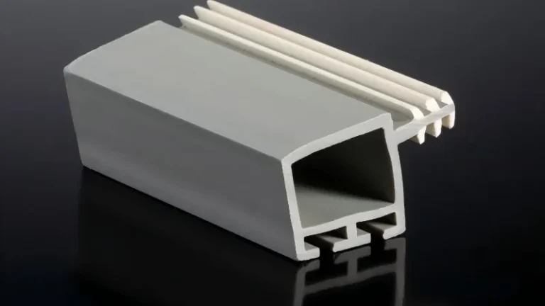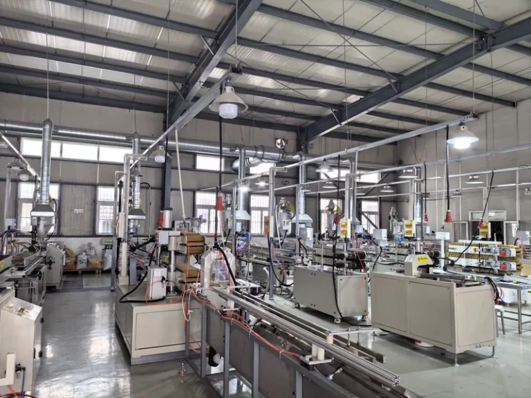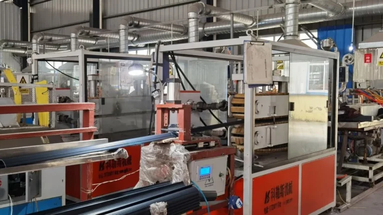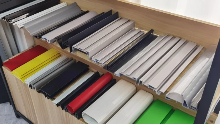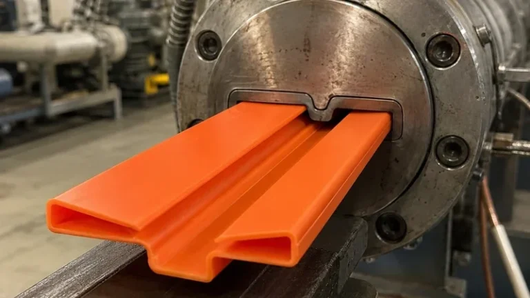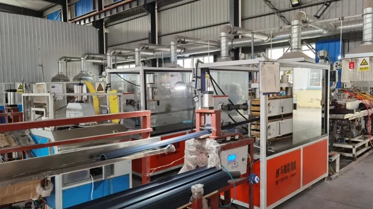
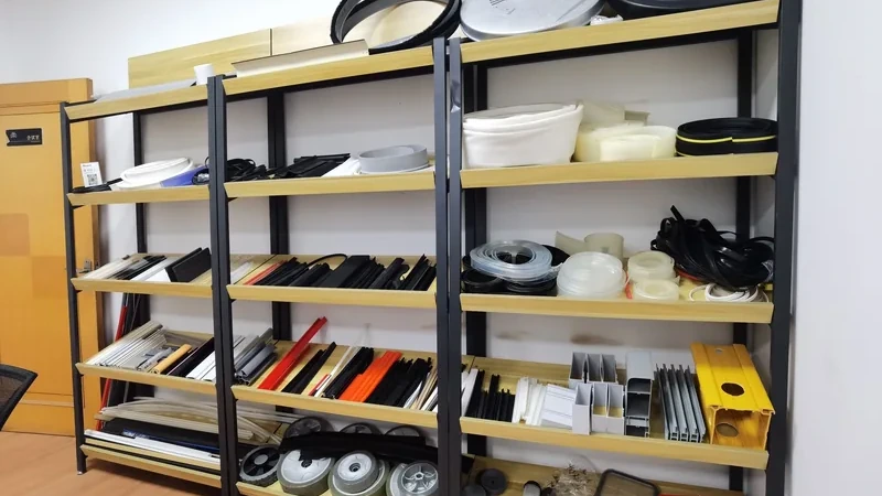
Before a production order is released, the buyer needs proof that a new profile can actually be made to the drawing. That proof is the first article inspection1. In profile extrusion it demands more care than in machining, because the final geometry is created jointly by the extrusion die, the calibration sleeve and the cooling setup, not by a single cutting tool. This guide explains what a first article for an extruded plastic profile should contain, how tolerances are measured, which failure modes appear most often, and what to agree with your supplier before the line trial.
- A first article inspection verifies production-representative samples against the drawing; it does not by itself prove long-term process capability.
- In profile extrusion, dimensions are set by the die head, calibration and cooling conditions, so samples must be cut at steady state.
- The scope covers full cross-section geometry, wall thickness, cut length, straightness, surface quality and every in-line secondary operation.
- Co-extruded profiles add layer thickness and interlayer adhesion to the checklist.
- Measurement methods and gauge ownership must be agreed before the line trial, not after a disputed dimension.
- A passing first article is the baseline document for the whole production program, including requalification triggers.
What Is a First Article Inspection for Extruded Plastic Profiles?
A first article inspection is the full dimensional and visual verification of production-representative samples taken from the first stable run of a new extrusion die. Its purpose is to confirm that the extruded profile matches the drawing before volume production is released. It is a tooling and design verification step, not a statistical quality control method.
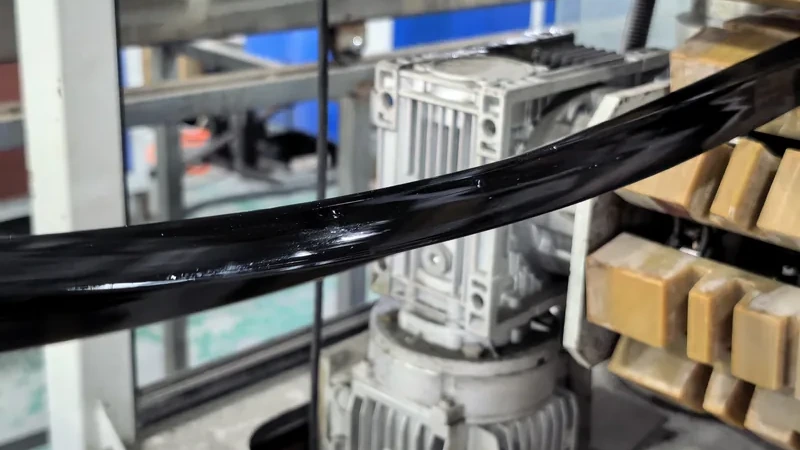
What makes this step different in extrusion is where the geometry comes from. A machined prototype reproduces the drawing almost independently of the production process. An extruded profile, by contrast, only reaches its final shape after the die head, vacuum calibrator, cooling bath and haul-off have reached thermal equilibrium together. The sample must therefore be produced on the production tooling, with the production material, at production line speed — a hand-cut piece from a laboratory extruder proves nothing about what the line will deliver.
Timing matters just as much. A line needs time to stabilize after startup; for a mid-size rigid profile this is commonly in the range of twenty to sixty minutes, depending on section size, material and calibration length. Samples pulled during that transient window drift in wall thickness and straightness as temperatures settle, so the inspection plan should state explicitly when in the run samples may be taken.
What Should a First Article Check Cover on an Extruded Profile?
The scope should cover the complete cross-section geometry, wall thickness at defined measurement points, overall width and height, cut length, straightness, surface condition and every secondary operation performed on the line. For co-extruded sections2, each layer thickness and the bond between layers belong in the scope as well.
For custom sections, work through the drawing feature by feature:
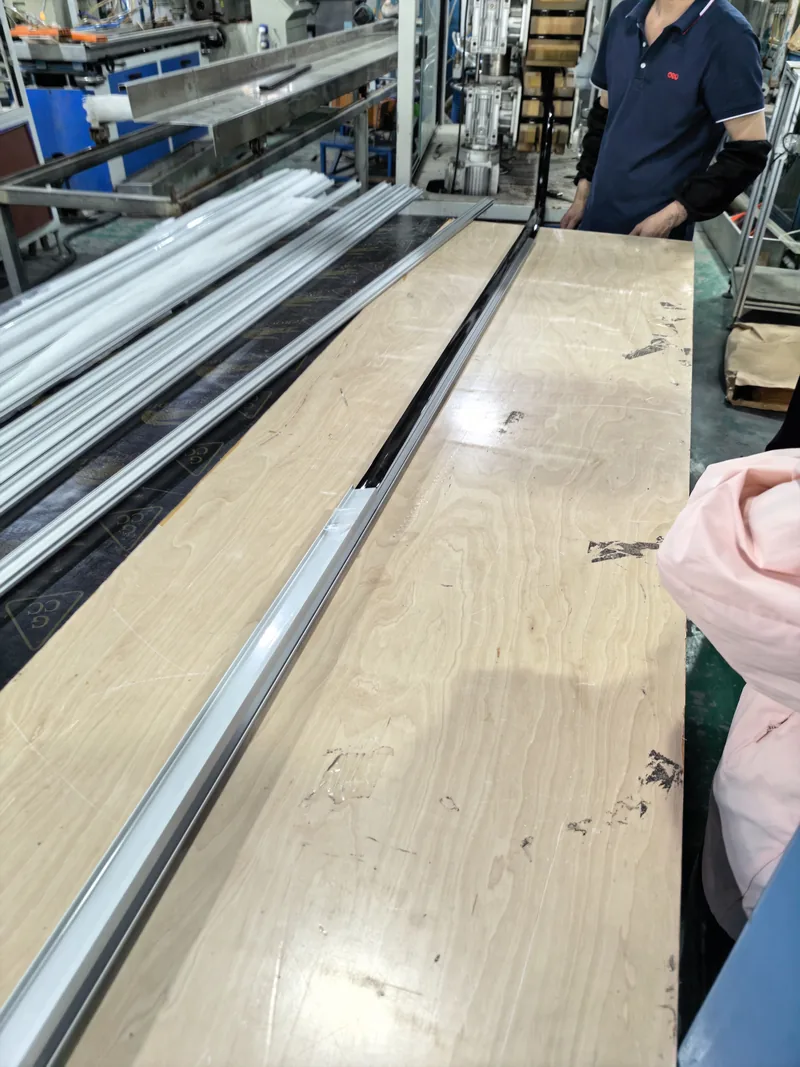
- Cross-section geometry. An optical scan or projector overlay against the CAD section is preferred; a caliper check of overall width and height alone misses local deviations on clip legs, sealing lips and snap features.
- Wall thickness. Measured at the points defined on the drawing, typically with a section cut and a micrometer. Uneven wall is the most common root cause of later warpage.
- Straightness and twist. Checked over the full cut length, not over a short offcut.
- Surface condition. Gloss consistency, flow lines and embossing depth where the line runs in-line embossing.
- Secondary operations. For in-line punching, hole position and burr height; for in-line printing, placement and adhesion.
- Cut ends. Squareness of the cut and absence of clamping deformation.
One extra check pays for itself: fit the first article into its mating part or a printed fixture. A profile can pass every drawing dimension and still fail in assembly because two tolerances stack unfavourably, and discovering that at the fixture is far cheaper than discovering it in volume production.
How Are Tolerances Specified and Measured on Extruded Profiles?
Extruded profiles normally carry a general tolerance frame for the overall section plus tighter, individually called-out tolerances on functional features. Measurement methods must be agreed before the trial, because a dimension that passes on an optical scanner can fail on a caliper.
Typical practice is to split the drawing into two classes. Overall width, height and general wall thickness follow standard profile tolerances; clip legs, snap features, sealing lips and punched holes receive individual tolerances because they interact with mating parts. Where tight cross-section control is required, a capable profile extrusion line can hold ±0.05 mm on selected cross-section dimensions, but this depends on material and section geometry and should be confirmed at the quotation stage rather than assumed. Our DFM checklist for extruded profiles covers how to mark these features before tooling is quoted.
Material properties are verified separately, usually through the compound certificate. ASTM D638 specifies the standard test method for tensile properties of plastics and is the default citation when a profile drawing requires tensile strength and elongation data on that certificate. For building products the scope widens further: EN 12608 specifies the profile geometry, impact resistance and heat reversion requirements for PVC-U window and door profiles, so first article approval for such profiles includes impact and heat reversion tests, not only dimensions. Where heat resistance matters, ISO 306 defines the Vicat softening temperature test3, a fast comparative indicator between material lots.
| Characteristic | Common method | Tolerance class | First article note |
|---|---|---|---|
| Overall width and height | Optical projector or 2D scanner | General profile tolerance | Depends on section size and material |
| Critical wall thickness | Section cut and micrometer | Tight individual call-out | Cut positions must match the drawing |
| Clips, lips, snap features | Optical scan against CAD | Tightest call-outs; ±0.05 mm achievable on selected dimensions | Highest assembly risk |
| Punched hole positions | Gauge or CMM | Functional call-out | Check burr height as well |
| Cut length | Length gauge | Job-specific | Verify squareness of the cut |
| Straightness | Straightedge and feeler gauge | Commonly ≤1 mm/m | Measure over the full length |
Indicative tolerance classes; actual values depend on material, section geometry and process capability, and should be confirmed with the supplier at the quotation stage.
ZetarVac commits to a minimum dimensional tolerance of ±0.05 mm on the profile cross-section, subject to material and section geometry, across profile widths from 5 to 600 mm on single-layer and multi-layer co-extrusion dies. Identify tight-tolerance features on the drawing before the die is quoted, so the tooling is designed for them instead of being corrected afterwards.
Which Failure Modes Show Up Most Often in First Article Runs?
The recurring findings are wall thickness imbalance, warpage or twist after the die, surface defects such as dull bands or flow lines, weak bonding in co-extruded layers and drift caused by a calibration that suits the section loosely.
Wall imbalance is the most frequent root cause. When one leg of a section runs thicker than its counterpart, the thick side shrinks more during cooling and the profile bows toward it. The correction lives in the die head and calibration setup, not in the inspection data, which is why a failed first article should be read as tooling feedback rather than as scrap to replace. Surface defects have a similar logic: dull bands and flow lines usually trace back to melt temperature or die land condition, and both are fixed at the tooling and process level.
Discussions about first articles usually fail on sampling discipline rather than on measurement:
"A first article sample can be cut a few minutes after the line starts up."False
During startup the melt and the calibration system are still moving toward thermal equilibrium, and wall thickness and straightness drift while temperatures settle. A sample from that window approves dimensions that the steady-state process cannot reproduce, which surfaces later as inconsistent production.
"First article samples must be taken only after the line has reached steady state."True
Steady state is confirmed by cutting consecutive lengths and checking that the same dimensions repeat within tolerance run after run. Only then does the sample represent what the production process will actually deliver.
How Many Samples Make a Valid First Article?
There is no universal number, but three to five consecutive cut lengths taken at steady state is common practice. A single sample proves the process reached the drawing once; consecutive samples show that it holds the drawing cut after cut.
For a simple single-layer profile, three consecutive lengths plus one retained sample are usually sufficient. For co-extruded sections, or sections carrying several tight called-out tolerances, five consecutive lengths give a better picture of short-term variation, and buyers planning a capability study can ask for a longer short run with capability reported on the critical dimensions. Whatever the count, keep at least one approved sample as a retained master: it becomes the physical reference for incoming inspection and for judging wear-related drift later in the program.
"Once the first article is approved, profile dimensions are locked for the program."False
Die lands and calibrators wear, material lots shift, and haul-off settings change during maintenance. Over months of production these effects move dimensions gradually, and a program without requalification discovers the drift at the assembly plant instead of at the extruder.
"First article approval should define requalification triggers alongside the sign-off."True
Typical triggers are a material grade change, die or calibrator maintenance, a line transfer, or an observed drift trend on critical dimensions. Writing them into the approval document turns the first article into the baseline for the entire production program.
What Happens After the First Article Is Approved?
Approval converts the samples and the dimension report into the baseline document for the program. The usual next step is a short capability evaluation on the critical dimensions, reported as a Cpk index4, before volumes are ramped. Once capability is demonstrated, incoming inspection can shrink to a few key dimensions checked per lot, with the retained master sample as the physical reference.
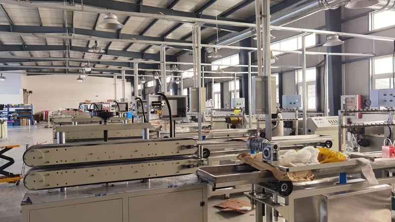
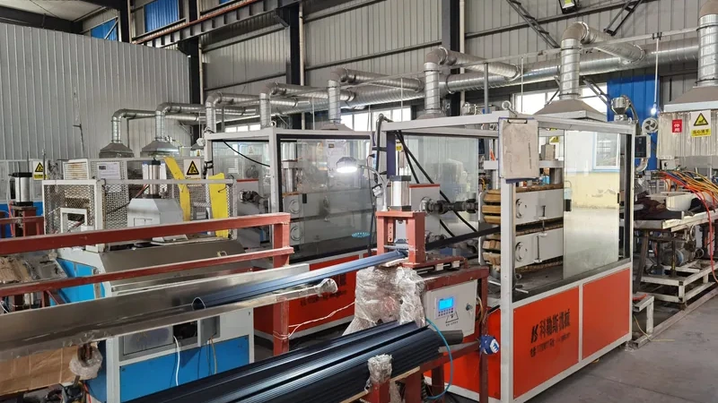
ZetarVac runs 7+ automated extrusion lines with in-line punching, embossing and printing, within a plant of 45+ production lines and a reference monthly extrusion capacity of about 300–500 tonnes, covering prototyping, small batch and large batch production. In-line operations enlarge the first article scope: hole positions, embossing depth and print placement all need verification on production samples rather than laboratory pieces.
Choosing a supplier that treats the first article as engineering dialogue rather than paperwork shows up in how they respond to a failed sample — with a die correction proposal and a re-trial plan, not just a replacement box. If you are comparing profile extrusion partners for a new section, our plastic extrusion molding overview and our page as a plastic extrusion manufacturer in China describe the tooling, materials and line capabilities behind that process.
FAQ
How long does a first article inspection take for a new extruded profile?
It depends mainly on tooling readiness. If the extrusion die already exists and has been debugged, sampling and measurement are commonly completed within days. A new custom section adds die design, trial and correction loops, so the schedule should be agreed per project instead of assumed.
Which documents should accompany a first article submission?
A dimension report with actual values for every called-out dimension, the material certificate, photographs of the samples and any assembly or functional check results. The report should also state which measurement equipment was used, so both parties read the numbers the same way.
Does first article approval include material testing?
Dimensional approval and material verification are separate activities. Material properties arrive through the compound certificate, citing standards such as ASTM D638, while application-specific tests — impact resistance or heat reversion for PVC-U window profiles under EN 12608, for example — are agreed case by case.
Who owns the gauges and measurement methods?
Both parties should agree in writing, before the trial, which measurements the supplier performs and which the buyer repeats on receipt. Ambiguity here is one of the most common sources of disputes over borderline dimensions.
What is checked specifically on co-extruded profiles?
Layer thickness at defined points, adhesion between layers, and the geometry of the functional layer. In a PP+TPV seat rail strip the flexible lip must seal and slide; in an ABS+TPU robot vacuum squeegee strip the TPU edge must wipe and resist wear while the ABS body carries the load.
If you are preparing a first article for a new extruded profile, send your drawing and target tolerances to our team through our service page to review the die design and measurement plan together — or request a quotation directly and include the mating part information so the inspection scope can be finalized in one pass.
-
First article inspection (FAI): The complete dimensional and visual verification of production-representative samples from the first stable run, performed before volume production is released. ↩
-
Co-extrusion: An extrusion process that combines two or more materials into a single profile in one pass, for example a rigid body with a flexible sealing lip. ↩
-
Vicat softening temperature: The temperature at which a needle penetrates a thermoplastic specimen to a defined depth under standard load, defined in ISO 306 and used as a heat resistance indicator. ↩
-
Cpk: A process capability index comparing the spread and centering of a measured dimension against its tolerance limits. ↩