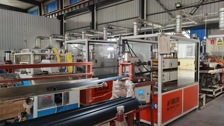
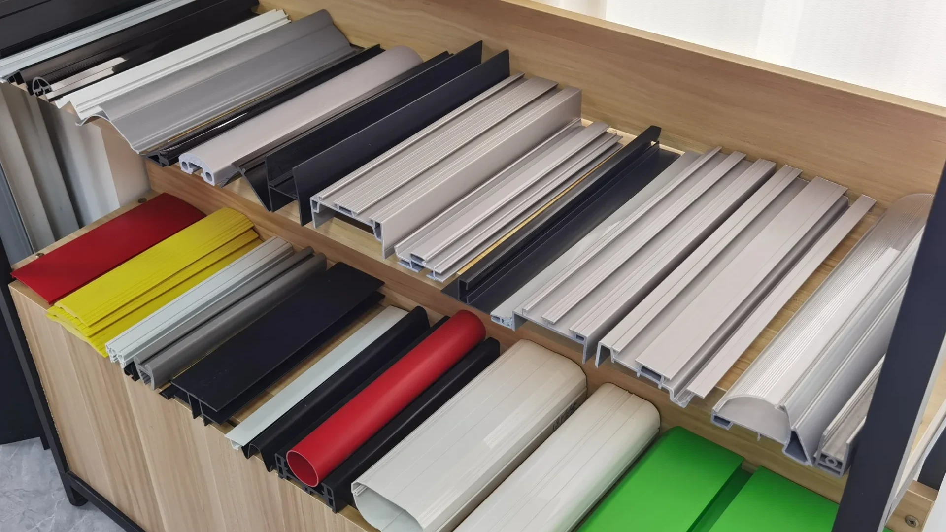
Every extruded profile starts at the same point: molten polymer forced through a shaped opening under controlled pressure and temperature. That opening is the extrusion die, and it shapes the finished part more than any other single tool in the line. Wall thickness distribution, section geometry, surface finish, layer structure and even how much the melt expands after exit all trace back to die design. This guide walks through the main die types used in profile extrusion, what each does well, where they cause trouble, and what a buyer should confirm before committing to a custom tool.
If you want the process itself first, the plastic extrusion molding overview covers the fundamentals; the rest of this article assumes them.
- The main extrusion die families are flat (plate) dies, profile dies, tubing and pipe dies, co-extrusion dies and foam dies.
- Melt leaving the die swells and is drawn down; final dimensions come from the die, calibration and haul-off speed acting together, not from the die alone.
- Co-extrusion dies combine two or three materials in one pass, typically pairing a rigid carrier with a soft sealing or wear layer.
- Tolerance on a profile cross-section is a joint outcome of die quality, calibration design and section geometry.
- Die maintenance is scheduled work—cleaning, land inspection, controlled storage—not a reaction to visible defects.
- Share your section drawing early so die type, material and layer structure can be reviewed together before steel is cut.
What Is an Extrusion Die and What Does It Control?
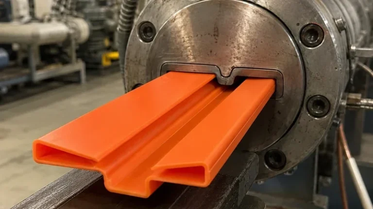
An extrusion die is the shaped tool assembly at the outlet of the die head that gives molten polymer its cross-sectional form. Through its flow channels, land geometry and opening profile, it sets the section shape, wall distribution and surface quality of the extrudate before any cooling happens.
Upstream of the die itself sits the die head: the adaptor, breaker plate and screen pack that filter the melt and convert the circular flow from the extruder into the geometry the tool needs. A profile die is rarely a simple plate. Complex sections are built from stacked steel plates, each cut to route part of the flow, so the melt is divided, redirected and recombined on its way to the die land1. Balanced flow matters more than any other single factor: if one leg of a section arrives faster than another, the finished profile distorts or shows wall variation that no downstream adjustment can fix.
A die is also tuned to a material. PVC, PP, ABS and TPU differ in viscosity, elasticity and heat sensitivity, and those properties set the land length, compression ratio and channel polish the tool requires. That is why a die is designed for a material family and is not freely interchangeable between them.
The Main Types of Extrusion Dies
Most industrial tooling falls into a handful of families. The useful question is not which type is best but which type matches your section, material and layer requirement. For a wider view of output shapes, the overview of types of plastic extrusions is a good companion.
Flat (plate) dies: These produce wide, shallow output such as sheet, board, flat strips and simple trims. The channel spreads melt from a circular inlet across the full width, usually through a coat-hanger or fishtail manifold designed so melt spends a similar residence time at the center and the edges. Width and thickness uniformity are the battlegrounds; a well-designed manifold plus adjustable lips or a choker bar is what keeps the output within tolerance across its full width.
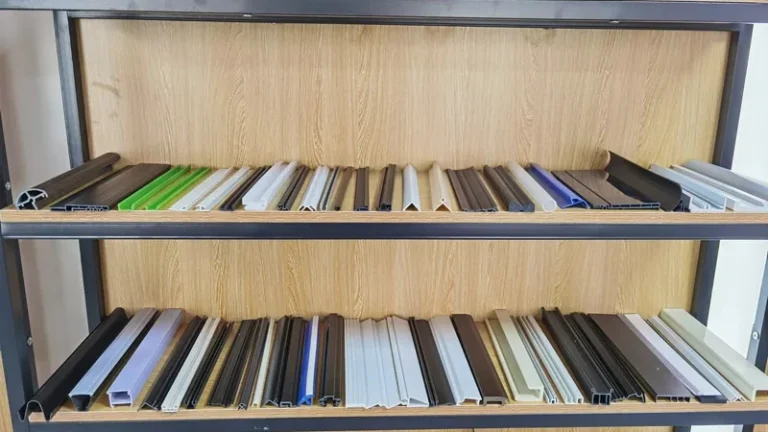
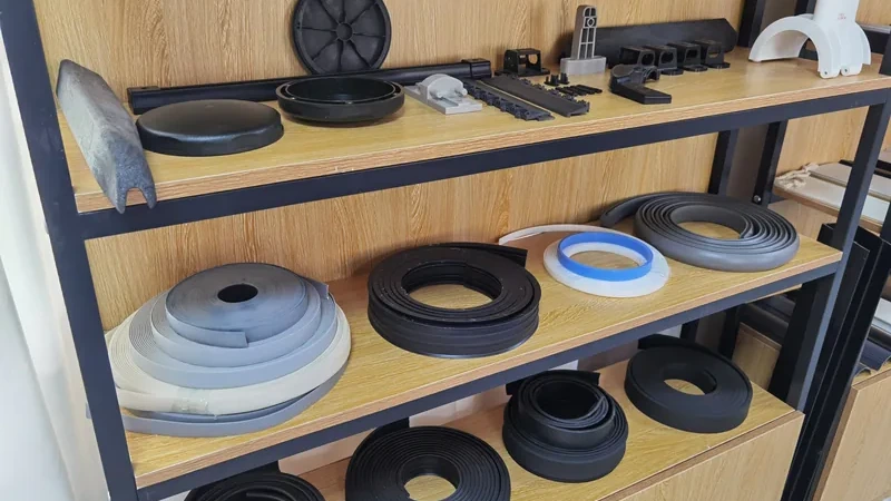
Profile dies: These are custom tools for every non-simple cross-section: channels, U-tracks, multi-cavity sections, sealing strips, edge trims and framing shapes. Sections range from a few millimeters up to 600 mm in width, and non-standard sections are developed directly to a customer drawing. Complex profiles are cut into stepped plates that balance flow to each leg of the section, and multi-cavity designs carry several voids through one body. This is where design experience shows fastest: an unbalanced channel appears as warp, wave or thin walls in the first trial and costs steel corrections to fix.
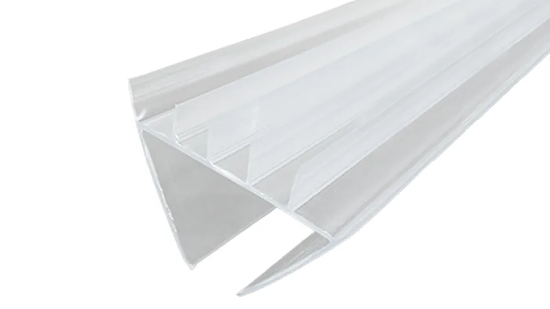
Tubing and pipe dies: These form annular output around a mandrel. Simple designs suspend the mandrel on spiders, which leave knit lines that must merge cleanly; spiral mandrel distributors rotate the flow instead and give a more homogeneous melt for pressure pipe. Dimensions are not a free choice here: ASTM D2241 specifies the dimension ratios and pressure ratings for PVC plastic pipe, so the die must be built to deliver a standardized outside-diameter system rather than an arbitrary size.
Foam dies: These handle a melt carrying a blowing agent, so the output expands after leaving the tool instead of shrinking. The opening is sized for that expansion and the downstream calibration accommodates it. The point is density reduction: gaskets, fillers and lightweight profiles where solid material would be heavier and costlier than the application needs.
How Do Co-Extrusion Dies Combine Two or Three Materials?
A co-extrusion die merges two or three melt streams into a single profile: either a feedblock joins the flows upstream and routes them through one tool, or a multi-manifold die head keeps each material in its own channel until just before the die exit. The result is one extruded profile with distinct functional layers.
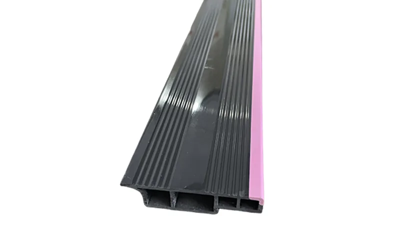
The usual arrangement pairs a rigid carrier with a functional layer: a hard structural body with a soft sealing lip or wear surface. Layer compatibility decides whether the bond holds—some combinations adhere naturally, some need a tie layer, and a few are chosen precisely because they do not bond, such as a soft lip that must flex independently of its rigid base. Layer thickness is controlled at the feedblock or manifold, so the rigid-to-soft ratio can be tuned without redesigning the whole tool.
ZetarVac runs single, double and triple layer co-extrusion in one pass, up to three layers, with combinations actually in production including PP+TPV, PP+TPE, PVC+TPU, ABS+TPU and TPV+CPVC. For a section that needs a rigid body and a different functional surface, layered extrusion is a proven production route rather than an experiment.
Two production examples show the pattern. An automotive seat slide rail strip co-extruded in PP+TPV combines dust exclusion, guiding, wear resistance and low friction with structural support and a flexible sealing lip in a single pass. A robot vacuum squeegee strip in ABS+TPU uses the rigid layer for support and the soft layer for wiping contact and wear resistance. Without a co-extrusion die, both parts would be two-piece assemblies.
Which Die Type Fits Your Profile Section?
Match the die family to section complexity, material and layer count. Simple strips and wide flat output run on flat dies; multi-void channels and sealing sections need a custom profile die; two or three materials in one section call for co-extrusion tooling.
| Die type | Typical output | Key design feature | Best fit |
|---|---|---|---|
| Flat (plate) die | Sheet, board, flat strips | Coat-hanger or fishtail manifold, adjustable lips | Wide, shallow, uniform sections |
| Profile die | Channels, trims, seals, multi-void sections | Stepped plates balancing flow to each leg | Custom cross-sections built to drawing |
| Tubing / pipe die | Tubes, hoses, pressure pipe | Spider or spiral mandrel distributor | Annular sections tied to dimension standards |
| Co-extrusion die | Two- or three-layer profiles | Feedblock or multi-manifold layer routing | Rigid body plus soft or decorative layer |
| Foam die | Lightweight profiles and gaskets | Expansion allowance at the die exit | Density-reduced applications |
Whatever the family, the section drawing drives die cost and risk before any steel is cut. Uniform wall thickness, generous inside radii, realistic tolerance calls and symmetric geometry all make flow balancing achievable. Deep reentrant pockets, abrupt wall transitions and tolerances copied from machined metal parts all raise the number of trial corrections. A design review against a die-focused checklist before quoting is the cheapest quality step in the project—the DFM checklist for extruded profiles and extrusion dies covers the specifics.
What Happens Between the Die Head and the Finished Profile?
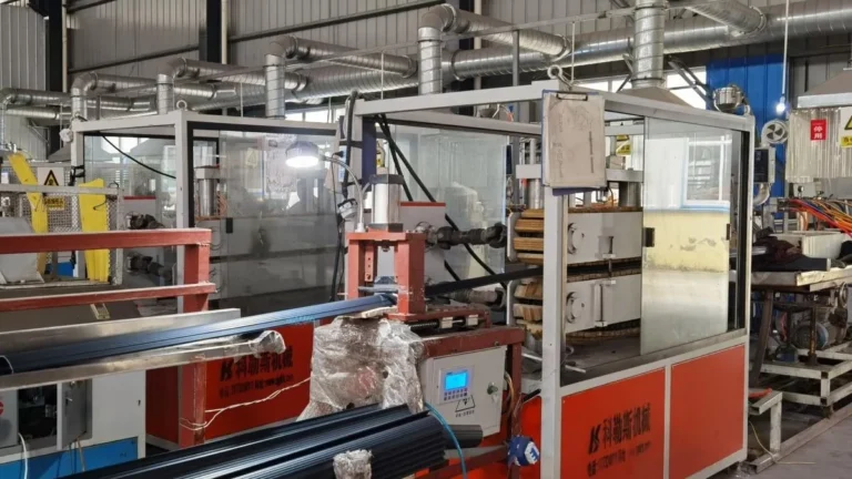
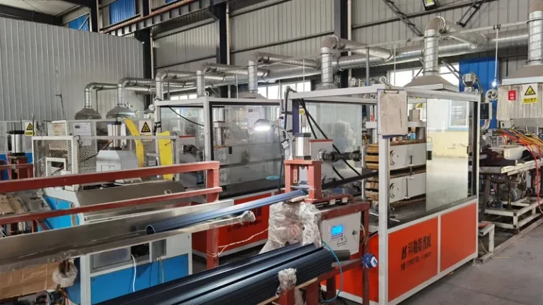
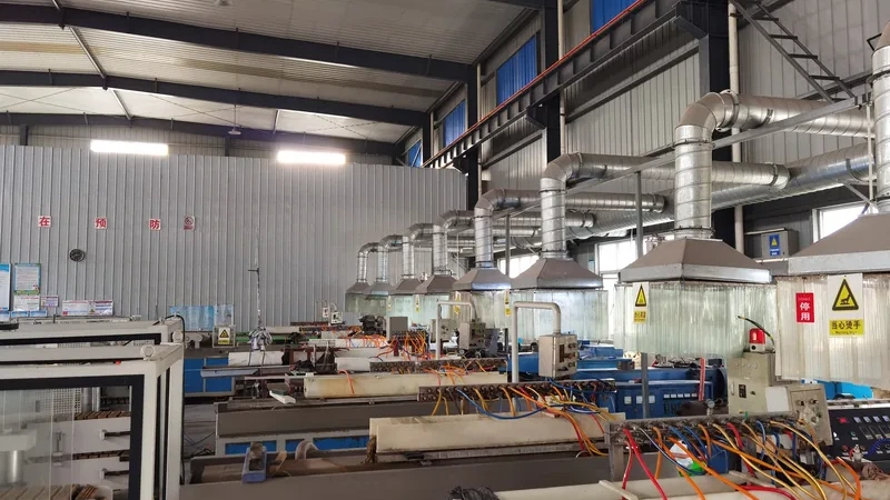
The melt leaving the die is hotter, thicker and shorter than the finished part. Die swell expands it, the haul-off draws it down, and vacuum calibration with water cooling locks in the final cross-section. Those downstream stages, not the die alone, deliver the tolerance on your drawing.
Melt under pressure inside the tool is elastically compressed. At the exit, that stored elasticity releases and the extrudate expands—die swell2—while the haul-off unit stretches it back down, the drawdown3 that sets the ratio between opening and finished size. The balance is tuned per material: a rigid PVC section and a soft TPE lip swell and draw differently even within the same tool family. Getting it right on the first trial is uncommon; expect a loop of measurement, small corrections and re-runs.
Downstream, the hot extrudate passes through a vacuum calibrator4 and a cooling bath. The calibrator sets external dimensions while the section is still soft, and cooling then freezes the shape. Asymmetry is the classic failure mode: a thick leg and a thin leg cool at different rates and the profile bows toward the thick side. Symmetric walls in the drawing are worth more than any straightening process afterwards.
"A first-article approval means the profile will hold that dimension for the entire production run."False
Tooling and process drift with temperature, material lots and wear on calibration surfaces. One approved sample validates the setup, not the distribution, so without ongoing measurement an out-of-tolerance length can ship before anyone notices.
"Stable profile dimensions come from continuously controlling melt condition, calibration and haul-off across the run."True
First-article approval only locks the starting point. Holding dimension over thousands of meters requires monitoring the variables feeding the die—melt condition, vacuum, cooling and line speed—so drift is caught while it is still a setting change, not a scrap pile.
Acceptance data keeps the conversation objective. Tensile values quoted for an extruded profile are normally measured to ASTM D638, the standard tensile test for plastics, which defines how a compound’s strength and elongation are measured so datasheets from different suppliers describe the same property. For PVC-U window and door profiles, EN 12608 specifies the profile geometry, impact resistance and heat reversion the finished product must meet, which pushes those requirements back into die geometry and compound selection before the first trial runs. Industry groups such as the SPE Extrusion Division publish deeper technical material on die flow design if you need it.
Across ZetarVac’s 7+ automated extrusion lines, profile widths run from 5 to 600 mm with a minimum achievable dimensional tolerance of ±0.05 mm on the profile cross-section, subject to material and section geometry. The tolerance your drawing can hold is a joint decision between die quality, calibration and section design, so review it early instead of inheriting it from a machining drawing.
How Are Custom Extrusion Dies Made and Maintained?
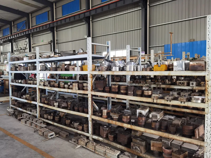
Custom dies are machined from tool steel, flow-polished and then tuned on the line: trial runs reveal how the melt actually behaves, and small steel corrections are cut until the profile holds dimension. After release, the tool needs scheduled cleaning, land inspection and controlled storage.
A single-layer strip die is a shorter build than a multi-cavity or co-extrusion tool, where layer routing, feedblocks and extra manifolds add machining time and tuning loops. In-line secondary operations change the picture too: punching, embossing and printing integrated on the extrusion line add function to the profile without a second handling step, but they tie die design to the downstream tooling and should be raised at the drawing stage.
The extruder feeding the die is part of the same system. Melt quality from the screw determines how predictably the die behaves, so the choice among types of extrusion screws is worth reviewing alongside die design rather than after it.
"Die maintenance only matters once a visible defect shows up on the profile."False
By the time a defect is visible, the tool has been degrading for meters or days: build-up in a channel or a worn land shows first as slow dimensional drift. Reactive maintenance turns a scheduled polishing into a re-cut, a re-trial and a stopped line.
"Dies need scheduled cleaning, land inspection and controlled storage between production runs."True
A die is a precision flow device, and residue hardening in a channel or a nicked land changes the profile before anything looks wrong. Planned cleaning and inspection keep the tool at its validated condition, and proper storage protects the polished flow surfaces between orders.
Treated this way, a die stays a production asset instead of a recurring project. The cost of scheduled care is small against a re-cut, a re-trial and a line waiting on steel.
ZetarVac develops non-standard profile sections to customer drawing, runs in-line punching, embossing and printing on its extrusion lines, and operates 45+ production lines across the plant. Raising secondary operations during the die and line conversation is what turns a single profile into a finished part without extra handling.
FAQ
How long does it take to build a custom profile die?
It depends on section complexity, layer count and how many tuning loops the first trials need. A simple single-layer strip die is a much shorter path than a multi-cavity co-extrusion tool with stacked flow plates. Ask a supplier to review your drawing for a realistic estimate rather than assuming a fixed figure.
Can one die run different materials?
Only within limits. A die is tuned to a material family’s viscosity and elasticity: similar compounds usually need minor adjustments, while a different family often requires flow re-tuning or a new land. Co-extrusion layer ratios add another variable. State the material on the drawing so the tool is designed for it from the start.
What tolerance can an extruded profile hold?
It depends on material, section geometry and calibration design. As an engineering reference, well-run lines can reach around ±0.05 mm on profile cross-section dimensions under favorable material and geometry, while complex or soft sections hold wider bands. Review the drawing with the die designer instead of copying tolerances from machined parts.
Why does my profile warp after cooling?
Warp usually traces to unbalanced flow or unbalanced cooling: one leg of the section carries more material, or one wall cools faster than another, so the profile bows as it sets. The fixes are die-side flow balancing, symmetric wall design and calibration—straightening after the fact treats the symptom, not the cause.
What should I send a supplier to start a die evaluation?
A section drawing with dimensions and tolerances, the material grade, the layer structure if any, the operating environment and expected volumes. With those inputs, die family, material fit and feasibility questions can be settled before any quotation. When you are ready to compare suppliers, share your drawings through ZetarVac’s plastic extrusion manufacturer page, or talk to an engineer to review die selection, material and layer structure together.
-
Die land: The parallel, straight section at the die exit where the melt takes its final shape; land length influences pressure drop, surface quality and dimensional stability. ↩
-
Die swell: The expansion of molten polymer as it leaves the die and elastic stresses relax, temporarily enlarging the extrudate before drawdown and calibration correct it. ↩
-
Drawdown: The stretching of the hot extrudate between the die exit and the haul-off unit, which reduces the cross-section and sets the ratio between die opening and finished size. ↩
-
Vacuum calibration: A sizing stage after the die head in which the hot extrudate is drawn through water-cooled, vacuum-assisted calibrators that set the final external dimensions. ↩