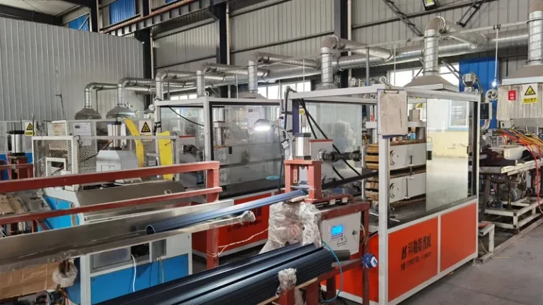
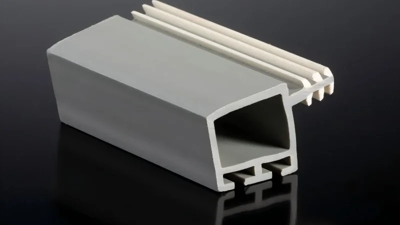
A custom profile rarely comes off the line right the first time. Between the moment a cross-section drawing is approved and the moment a stable run produces sellable meters, there is one decisive step: the die trial. This guide walks through the full trial and prototyping process — what is actually adjusted, which tolerances must be frozen first, the failure modes that cost the most time, and how many iterations a buyer should budget for before committing to volume production.
- A die trial validates the extrusion die, vacuum sizing tooling, cooling, and haul-off as one system, never the die alone.
- Most custom extruded profiles need two to four trial iterations before dimensions hold across a full run.
- Freeze material grade, cross-section tolerances, and the inspection method before die steel is cut; late changes reopen the tool.
- A passed first article is a snapshot, not proof of stability — a monitored production run is what releases a die.
- Co-extruded sections add flow-balance variables, so plan extra trial time and checkpoints.
What Happens During an Extrusion Die Trial?
A die trial is a controlled test run in which the extrusion die, sizing fixtures, cooling, and haul-off are tuned together until an extruded profile meets its drawing. The line starts at conservative settings, the emerging profile is measured against the cross-section, and the die gap, vacuum, and line speed are adjusted step by step. The output is not a few good samples but a documented process window.
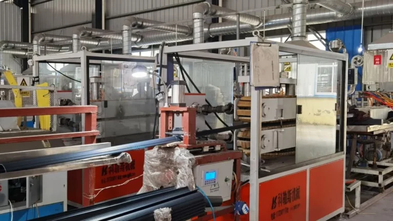
Trials follow a recognizable sequence. The resin is dried and preconditioned to specification, the extruder barrels are brought to melt temperature, and the die head is purged until the melt stream is clean and stable. Early extrudate is pulled slowly by hand and checked for gross problems — uneven walls, ovality, visible melt fracture — before any attempt at speed. Only when the ribbon of polymer looks uniform does the profile enter the vacuum sizing table, where dimension control shifts from the die lips to the sizing sleeves and cooling distribution.
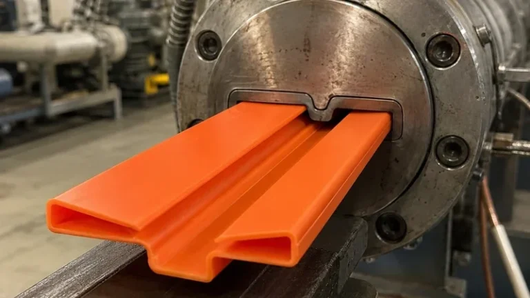
Die swell1 is the first physics problem every trial team confronts. As the melt leaves the die, elastic recovery makes it expand, so a die cut to nominal size will generally produce a profile that is too large at the critical dimensions. Experienced die designers compensate with smaller openings and longer land lengths, but the correction is material-specific: a rigid PVC compound and a soft TPE swell differently through the same die head. This is why trials are run with the production resin, not a convenient substitute.
Draw-down is the second lever. The haul-off unit pulls the profile slightly faster than the extruder delivers it, which thins the walls and stretches the section. Adjusting the ratio between extruder output and haul-off speed changes wall thickness continuously, while the die fixes the shape. Vacuum level in the sizing sleeves then locks the outer dimensions and defines the detail in grooves, ribs, and snap features.
Throughout the run, measurements happen both hot and cold. Operators gauge the emerging profile at the sizing table, but acceptance dimensions are only recorded after the part has fully cooled and stabilized, because shrinkage continues for hours on some materials. Calipers, pin gauges, optical projectors, and laser scanners all appear on trial benches; the instrument should be the same one intended for production inspection, so the trial result and the incoming-inspection result speak the same language. If you are new to the hardware itself, this overview of what a die is in the extrusion process explains the anatomy of a die head and its land region.
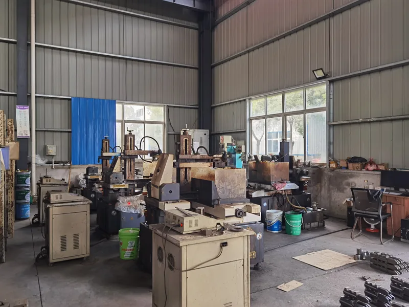
How a Custom Profile Moves From Drawing to Prototype
Before any steel is cut, the cross-section goes through a design-for-extrusion review. Walls are checked for uniformity, corners for radii, and ribs and hollows for whether they can actually be sized and cooled. A section that looks perfect on screen can be impossible to hold in tolerance if it mixes a heavy structural wall with a thin decorative lip.
Resin selection is locked at the same stage, because it drives die swell, shrinkage, and cooling behavior. A profile for cable protection may specify flexible PVC for insulation and softness, a structural frame may call for rigid PVC or ABS, and an outdoor trim may require an ASA weatherable grade. Extrudability is matched against section geometry at this review, not chosen afterwards.

Prototyping does not require committing to full production tooling first. Depending on the section, a simplified prototype die can prove the geometry, or an existing die with similar flow characteristics can be adapted for short runs. The useful output of prototyping is not just a sample part — it is the measured deviation between the drawn cross-section and what the process actually delivers, which feeds directly into the production die design. Teams looking for deeper die design references can draw on industry resources such as the SPE Extrusion Division.
ZetarVac develops non-standard profile sections to customer drawings across a 5–600 mm width range and can hold a minimum dimensional tolerance of ±0.05 mm on the profile cross-section, subject to material and section geometry. For a buyer, that means tolerance decisions can be validated at trial on the same equipment class that will run production, rather than on a one-off lab line.
Keep the prototype phase short and purposeful. Every design change after the production die is ordered — a radius here, a wall there — reopens the tool and adds a correction loop. The cheapest trial is the one where the drawing was right before the die was machined.
Which Tolerances Should You Freeze Before the Trial?
Material grade, cross-section dimensions, and the inspection method must be frozen before the die is cut. Changing any of them mid-trial invalidates every correction already made and effectively restarts the loop. Process settings — melt temperature, vacuum, line speed — are deliberately left open for tuning.
Drawing language matters as much as numbers. ISO 1163 defines the designation and specification system for unplasticized PVC moulding and extrusion materials, so a material callout written to that standard means the same compound family at trial, at incoming inspection, and at volume production. For mechanical properties, tensile values reported on a first article2 are normally generated to ASTM D638, the default tensile test cited for extruded profiles, which fixes specimen geometry and test speed so results stay comparable across suppliers. Agree on both before the first chip is cut.
How tight each callout should be depends on material, section complexity, and line capability — the point of the table below is the decision logic, not universal numbers:
| Feature | What to specify at trial | When to tighten it |
|---|---|---|
| Overall width or height | Commercial band agreed at review; the tightest practical class on the profile cross-section is ±0.05 mm | Mating or sliding assemblies |
| Wall thickness | A percentage-of-nominal band agreed per material, not a blanket figure | Structural or pressure-bearing sections |
| Thickness across rigid–soft transitions | Separate callout from the overall width band | Co-extruded profiles with sealing lips |
| Straightness (bow) | A millimetre-per-metre class callout | Long rails, guides, visible trims |
| Cross-section flatness | Agreed only on sealing and mounting faces | Sealing and mounting surfaces |
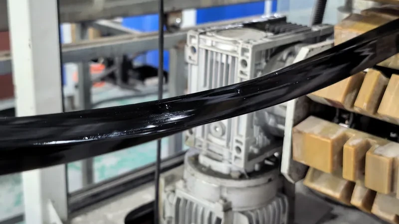
Tolerances tighter than the process needs cost money twice: first in extra die corrections, then in scrap during production. The right question for each dimension is not how tight it can be, but which faces actually mate, seal, slide, or show. Those carry the tight callouts; everything else gets commercial tolerance.
"Once the first article passes inspection, the die is finished and volume production can start immediately."False
A first article is one short snapshot taken under one set of conditions. Melt temperature drift, resin lot changes, and screw wear all move dimensions over hours, not minutes. Skipping the stability run is how buyers discover tolerance violations in delivered lots instead of at the vendor’s line.
"A first article should be followed by a monitored stability run before the die is released."True
A proper release run holds the line at production speed for a defined length of output and charts key dimensions over time. If the trend stays inside tolerance, the process window is real and the die is ready for volume.
In practice the release run doubles as process documentation. The settings that held dimensions — barrel temperatures, screw speed, vacuum, haul-off speed — become the reference window, and any future deviation is judged against that window rather than against a memory of a good day.
Common Failure Modes in Die Trials and How to Fix Them
Most trial failures trace back to a short list of root causes: uneven melt flow in the die, unbalanced cooling, incorrect draw-down, poor resin condition, or a section that was never extrusion-friendly. Each leaves a characteristic signature on the part.
- Thick or thin legs, heavy corners. Die swell is rarely uniform across a section; the melt travels farther to reach outer legs and arrives with different pressure. The first fix is flow balancing in the die — land length changes and flow restrictors — before anyone reshapes the profile.
- Waviness and periodic ripple. This usually comes from haul-off slippage or vacuum fluctuation, not the die. Check belt pressure, vacuum sealing, and cooling water temperature before touching steel.
- Bow and warp. Asymmetric sections cool unevenly, and the cold side contracts first, pulling the profile into an arc. The correction lives in cooling distribution and sizing alignment; adding straightness tolerance to the drawing alone fixes nothing.
- Melt fracture and rough surfaces. Excessive shear at the die land shows up as surface haze or sharkskin. Higher melt temperature, polished lands, or a slower initial line speed usually clear it.
- Dimensional drift over the run. Resin moisture, regrind percentage, and melt temperature creep all shift dimensions hour by hour. Log the settings, not just the measurements, or the drift cannot be diagnosed.
"If a trial profile is out of dimension, the die has to be re-cut from scratch."False
A large share of dimensional problems are solved at the sizing tank and haul-off, not in the die: vacuum level, cooling distribution, and draw-down ratio all move dimensions without machining anything. Ordering steel changes before these levers are exhausted wastes lead time and can ruin a die that was never wrong.
"Process and sizing adjustments should be exhausted before any die correction is approved."True
A disciplined trial separates process deviation from tool deviation. When a defect persists at the same location after the full process window has been explored, it is built into the flow channel, and only then is a targeted die correction justified.
The practical value of this discipline shows up in the iteration count. Teams that diagnose before machining typically converge in two to three loops; teams that re-cut steel on every deviation can double that number and still miss the root cause.
How Many Trial Iterations Should You Budget For?
For a single-material profile of moderate complexity, two to four trial iterations are a realistic budget; complex hollow sections, tight-tolerance sections, or unfamiliar resin and die combinations can require more. Each iteration includes the correction itself, a re-setup, and a full measurement cycle.
Co-extrusion raises the count because a second melt adds a second set of variables. Layer interface position, flow balance between the two materials, and adhesion at the bond line all need to be proven, not just the outer dimensions. A rigid core with a soft functional lip — the combination behind an automotive seat slide rail strip co-extruded in PP and TPV, or a robot vacuum squeegee strip where ABS provides rigid support and TPU provides the flexible wiping edge — must show both materials holding their own tolerances simultaneously.
For a closer look at how multi-layer flow is organized inside the tool, see this guide to co-extrusion die heads for multi-layer profiles.
ZetarVac runs co-extrusion up to three layers in a single pass, with combinations actually in production including PP+TPV, PP+TPE, PVC+TPU, ABS+TPU, and TPV+CPVC. Multi-layer capability on the same platform as single-layer profile extrusion means one trial plan can cover both material systems.
Set iteration expectations at the quotation stage, not after the first trial fails. A supplier who quotes one perfect trial is either optimistic or planning to charge for corrections invisibly; a supplier who quotes a trial plan with defined checkpoints is one you can hold to a schedule.
From Trial Run to Stable Production
Passing the trial produces more than a good sample. The handover package should record the process window3 — barrel and die temperatures, screw speed, vacuum levels, haul-off speed, cooling water temperature — together with the measurement results that prove it. With that document, a different shift on a different day can reproduce the same profile, which is the entire point of a trial.
In-line secondary operations need their own checkpoints. Punching, embossing, and printing integrated into the extrusion line must be proven at production speed during the trial phase, because a feature that works at slow trial speed can misregister at full throughput. Confirming these on the same run that releases the dimensions prevents a second qualification loop later.
Finally, the parameters that survived the trial become the baseline for ongoing optimization — output rate, scrap rate, and changeover time are all tuned from that starting point. A structured walk-through of profile extrusion process parameters shows how each setting interacts with the next.
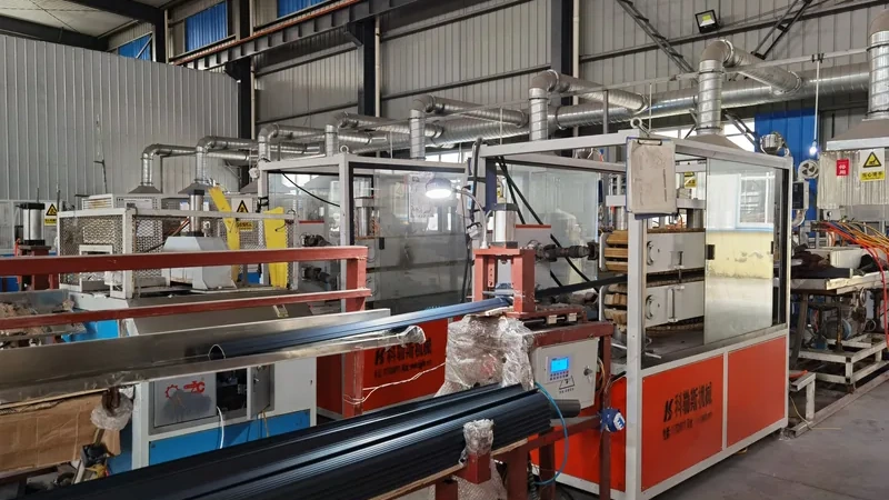
ZetarVac runs more than seven automated extrusion lines within a plant of over 45 production lines, with reference monthly capacity of roughly 300–500 tonnes across the extrusion lines, and supports prototyping, small batch, and large batch production. A profile validated in trial therefore transfers to volume on the same equipment class without re-qualifying a new supplier.
When the buyer is ready to compare suppliers, the questions worth asking are concrete: how many correction loops the quote assumes, which instrument will be used for acceptance, and whether the trial line matches the production line. Our overview of plastic extrusion molding capabilities covers the full line range and is a useful baseline for that conversation.
FAQ
How long does a typical die trial take?
A single trial session commonly runs one to three days, depending on section complexity and whether a die correction is needed between runs. Added iterations, co-extrusion layers, or in-line secondary operations extend the schedule; the trial plan should state this explicitly.
Should the trial run the production resin, or is a substitute acceptable?
Always the production resin. Resin families swell, shrink, and flow differently through the same die head, so a trial passed on a substitute compound proves little about the production material. Lot-to-lot consistency should also be checked before the release run.
What should I prepare before requesting a die trial?
Bring the cross-section drawing with tolerances, the material specification, the application environment, and the intended inspection method. Geometric dimensioning and tolerancing4 on mating features removes most of the ambiguity that causes correction loops. The more complete the package, the fewer iterations you pay for.
Does co-extrusion change the trial plan?
Yes. Two melts mean two flow balances to prove, plus interface position and adhesion at the bond line. Plan at least one extra iteration and require measurement of each layer, not just the overall section.
How do I move from an approved prototype to production pricing?
Send the approved drawing, target volumes, and tolerance requirements, then request a quote with our team. We will review extrudability, propose a trial plan with defined checkpoints, and confirm tooling scope before any steel is ordered — contact us to start the review.
-
Die swell: the expansion of a polymer melt as it exits the die, caused by elastic recovery of the melt; extrudate dimensions are typically larger than the die opening. ↩
-
First article inspection (FAI): a documented verification that a first production sample meets all drawing requirements, performed before series release. ↩
-
Process window: the range of process settings within which a profile stays inside tolerance; wider windows mean more stable production. ↩
-
GD&T: Geometric Dimensioning and Tolerancing, a standardized system for defining engineering tolerances on drawings, including form, orientation, and location of features. ↩