Material extrusion is the backbone of continuous plastic manufacturing: it turns raw thermoplastic pellets into meters upon meters of consistent, constant-cross-section product. Yet the term gets used loosely in buyer conversations, and that confusion becomes expensive when drawings go out for quotation. This guide defines the process the way a plant engineer would, walks through every stage of a profile extrusion line, and sets realistic expectations for materials, tolerances, and the road from first article to stable volume production.
- Material extrusion is a continuous melting-and-shaping process: thermoplastic is forced through a die head to form a constant cross-section, then sized, cooled, and cut to length.
- Dimension control lives mostly downstream of the die head, in vacuum calibration and cooling — not in the tooling alone.
- Material choice drives everything: a PVC window profile, an ABS automotive trim, and a TPE gasket follow different specification and testing logic.
- Cross-section tolerances near ±0.05 mm are achievable, but only in favorable material-and-geometry combinations.
- Co-extrusion, up to three layers, solves property conflicts a single polymer cannot — at the cost of a more complex die head.
- First-article approval is a checkpoint, not proof of process stability; judge volume readiness with dimensional data taken over time.
What Is Material Extrusion?
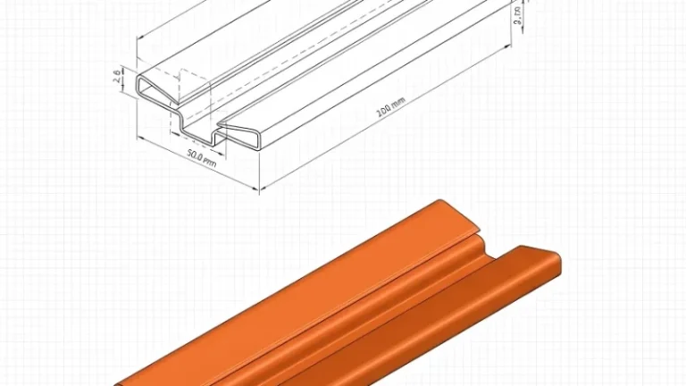
Material extrusion is a continuous process in which thermoplastic material is melted, pressurized, and forced through a shaped die head, producing a part with a constant cross-section that can run to any practical length. Profile extrusion, tube extrusion, and sheet extrusion all share this one principle; only the tooling and downstream sizing change. The output — an extruded profile such as a window section, pipe, edge trim, or sealing strip — is made in a single uninterrupted pass.
The word “continuous” carries most of the engineering weight. Unlike processes that produce one part per cycle, an extrusion line runs for hours on the same setup, which is why per-meter cost drops sharply at volume and why long products with no weld lines along their length are natural territory for this process. It also explains the discipline the process demands: screw speed, melt temperature, haul-off speed, and cooling rate must stay locked in sync, because the product is never finished until the moment it is cut.
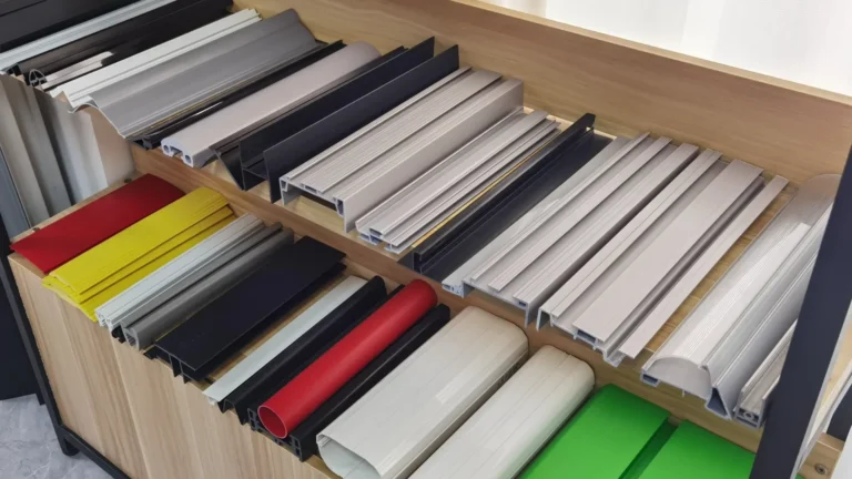
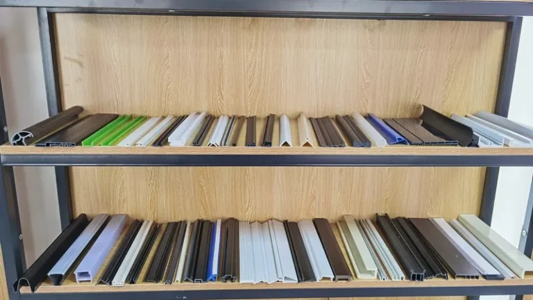
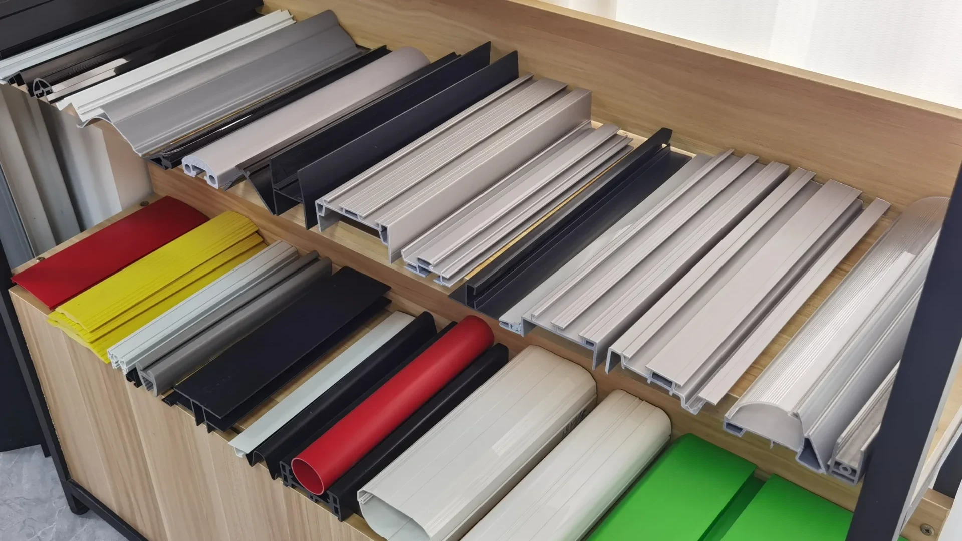
The “material” part of the term matters just as much. The same machine platform produces a soft TPE gasket and a glass-filled PP structural profile, but screw design, die land, cooling regime, and tolerance expectations change completely between them. In practice, single-layer, double-layer, and triple-layer co-extrusion plus foam extrusion cover most industrial needs, and custom non-standard sections are developed directly from a customer drawing. For a wider map of the process family, see our plastic extrusion molding overview.
How a Profile Extrusion Line Works, Stage by Stage
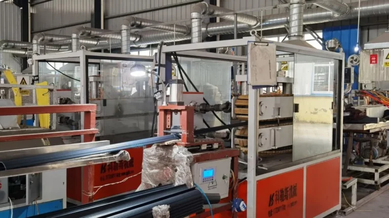
A profile extrusion line is a chain of stations, and section quality is decided by the weakest link. The journey runs roughly as follows: feed and drying, screw melting, the die head, vacuum calibration, cooling, haul-off, in-line operations, and finally cutting or coiling.
Feed and drying come first, and they are skipped at the buyer’s peril. Hygroscopic polymers such as PC, PA6, and PA66 pick up moisture that flashes into steam inside the barrel, leaving voids and surface streaks in the finished profile; every such resin needs its own documented drying cycle before it reaches the screw. Melt temperatures follow material logic rather than one universal number: rigid PVC commonly processes around 170–200 °C, PP near 200–250 °C, and PC up toward 270–310 °C, always subject to the compound and the machine.
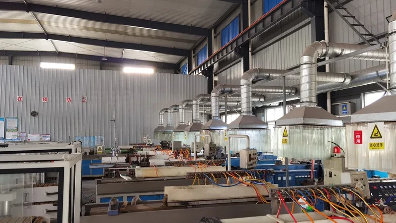
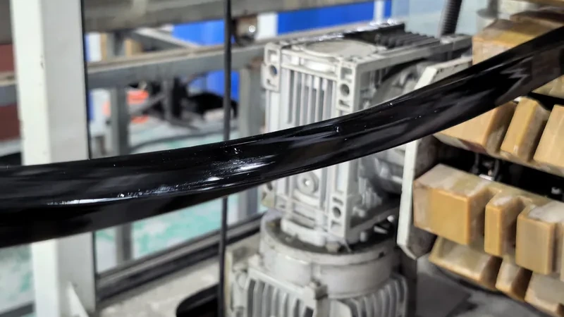
Downstream of the extruder, the melt enters the die head, where flow channels distribute material evenly across the section. The extrudate swells slightly as it exits — a viscoelastic effect called die swell1 — so die openings are cut undersize and geometry is recovered in calibration. A vacuum sizing table then presses the still-soft section against a water-cooled calibration tool, fixing the outer shape while cooling troughs remove heat through the wall. Belt haul-off2 draws the section at a speed matched to extruder output; that ratio, not the die alone, sets final dimensions. Punching, embossing, and printing can be added in line before the saw cuts to length or the product winds onto a coil.
Modern lines make this synchronization visible. Every station reports to a central control panel, and a trained operator reads melt pressure and temperature trends the way a pilot reads instruments — drift in one signal predicts dimensional drift meters downstream.
ZetarVac runs 7+ automated extrusion lines with a maximum profile width of 600 mm, within a plant of 45+ total production lines and a reference monthly capacity of roughly 300–500 tonnes across the extrusion lines. For a buyer, that means wide or multi-cavity sections are routine work on standard equipment, not special accommodations.
Which Materials Suit Which Profiles?
Almost any thermoplastic can be extruded, but each polymer punishes a different mistake: PVC punishes overheating, PC punishes moisture, PA punishes sloppy drying, and TPE punishes the wrong hardness selection. The practical question is not whether it can be done, but which material matches the duty, the environment, and the tolerance you actually need.
| Material | Typical extruded applications | First property to verify | Practical note |
|---|---|---|---|
| Rigid PVC | Window and door profiles, decorative trims, pipes, sealing strips | Impact strength and heat reversion | Construction profiles fall under EN 12608 |
| ABS | Automotive and industrial profiles, decorative parts | Impact strength and surface finish | Paintable, good cosmetic behavior |
| HDPE | Pipes, edge trims, guide rails, wear strips | Wear resistance and stiffness | Tough and forgiving to process |
| PP | Profiles, pipes, functional parts | Stiffness and heat deflection | Low density keeps part cost down |
| PC / PMMA | Transparent pipes, light covers, clear profiles | Optical clarity and Vicat softening point | Demands careful drying and clean lines |
| TPE / TPV | Sealing strips, gaskets, automotive seals | Compression set and hardness | Often co-extruded onto rigid carriers |
| PA6 / PA66 / POM | Precision profiles, guide rails, wear parts | Dimensional stability and friction | Requires strict drying discipline |
Construction-grade PVC deserves its own sentence of caution. EN 12608 specifies the profile geometry, impact resistance after ageing, and heat reversion limits that unplasticized PVC profiles for windows and doors must meet3, so a window profile quoted on price alone — without compound classification to a system such as ASTM D17844 — may satisfy the drawing and still fail the building code. For mechanical properties, tensile behavior of the compound is normally measured per ASTM D638, the default tensile test cited for extruded profiles.
Outdoor profiles shift the question toward weathering. ASA holds color and gloss where ABS chalks, and laboratory light-source exposure under ISO 4892 is the standard way to compare candidate compounds before committing tooling money. When the buyer is ready to compare suppliers, the material table above is a fairer starting point for the conversation than unit price per kilogram.
"Any rigid PVC compound will pass window profile requirements as long as the dimensions are right."False
EN 12608 constrains geometry together with impact resistance and heat reversion, properties that come from the compound formulation rather than from the die. A dimensionally perfect profile made from an unsuitable compound fails certification and ages poorly outdoors.
"Material selection and die design must be reviewed together, before tooling is cut."True
Because shrinkage, die swell, and cooling behavior differ between polymers, the same section cannot simply be re-cut in a cheaper resin. Reviewing compound and die head as one package prevents costly rework after first trials.
What Tolerances Can an Extruded Profile Hold?
On a favorable material-and-geometry combination, cross-sectional tolerances around ±0.05 mm are achievable in profile extrusion; on complex multi-wall sections or high-shrinkage polymers, expect commercial tolerances several times wider. Tolerance is negotiated between polymer behavior and section geometry — it cannot simply be written into the drawing and enforced.
Three effects fight the dimension. Die swell varies with screw speed and melt temperature, so the section breathes as conditions drift. Shrinkage continues after the profile leaves the cooling trough and depends on wall thickness, meaning thick and thin areas of the same section stabilize at different times. And asymmetric sections warp toward the hotter side, because the last region to cool keeps shrinking. A skilled die head designer pre-compensates for all three, but the compensation is material-specific.
Specify what matters: mark the functional dimensions that mate with other parts and leave the rest at standard commercial tolerance. Inspection is straightforward — a laser micrometer scanning the running profile catches drift in real time, while a cut sample under a profile projector verifies the full cross-section against the drawing at intervals.
"A tolerance of ±0.05 mm can be held on any profile section if the supplier is good enough."False
Tolerance capability depends on material shrinkage and section geometry, not on effort alone. Demanding laboratory-grade tolerance on an asymmetric, multi-wall section forces slow lines, heavy scrap, and a price premium — or outright failure in production.
"Tolerance capability must be confirmed against the specific material and section geometry."True
Profile widths from 5 mm to 600 mm change the difficulty completely, and so does each polymer’s shrinkage behavior. A supplier who reviews the drawing section by section before quoting is doing this evaluation correctly.
If your drawing already carries tight tolerances on every line, spend a review pass deciding which dimensions truly function. Relaxing the cosmetic ones typically lowers tooling risk and per-meter cost more than any negotiation on price.
ZetarVac’s published capability is a minimum dimensional tolerance of ±0.05 mm on the profile cross-section, explicitly subject to material and section geometry, with profile widths from 5 to 600 mm. In-line punching, embossing, and printing run on the same pass, so secondary operations add no extra handling tolerance on top of the extrusion tolerance.
When Does Co-Extrusion Justify Its Cost?
Co-extrusion pays for itself when one polymer cannot deliver two conflicting properties in a single section: rigid support with a soft sealing lip, a colored surface over a tough core, or a low-friction layer on a wear rail. If a single material can do the job, the simpler single-layer die head always wins on cost and process stability.
A co-extruded section is built from two or three melt streams joining in one die head, and modern lines run up to three layers in a single pass. The combinations ZetarVac actually runs — PP+TPV, PP+TPE, PVC+TPU, ABS+TPU, and TPV+CPVC — each solve a recurring product problem. An automotive seat slide rail strip in PP+TPV combines dust exclusion, guiding, wear resistance, and low friction with structural support from the PP and a flexible sealing lip from the TPV. A robot vacuum squeegee strip in ABS+TPU uses the ABS for rigid support and the TPU for flexible, wear-resistant wiping contact.
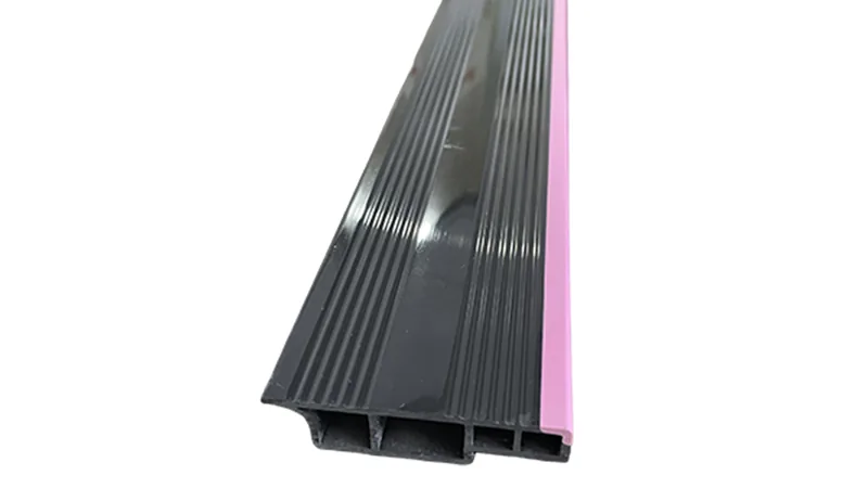
The economics are simple to state and easy to misjudge: a co-extrusion die head costs more than a single-layer equivalent, and balancing two or three melt flows takes longer to set. The payoff is eliminating an assembly step, a secondary gasket, or an adhesive bond — along with their failure modes. When those downstream costs are counted honestly, the more expensive tooling frequently wins. For a deeper look at how multi-layer flows are balanced inside the tool, see our article on co-extrusion die heads for multi-layer profiles.
ZetarVac’s extrusion offering covers single, double, and triple-layer co-extrusion as well as foam extrusion, with verified combinations including PP+TPV, PP+TPE, PVC+TPU, ABS+TPU, and TPV+CPVC. If your product currently joins a rigid profile and a soft seal by assembly, a two-layer co-extruded replacement is a fair engineering question to put to any supplier.
How Do You Tell a Good First Article from a Stable Process?
A first article proves the die head can make the section; a stable process proves it can keep making it, hour after hour, at rate. The difference is drift — slow movement of dimensions as tooling wears, melt conditions wander, and material lots change — and it only appears in data collected over time.
A serious qualification run therefore looks boring: the same section measured at fixed intervals, melt pressure and temperature logged continuously, and the resulting charts reviewed against the drawing. Most dimensional drift traces back to a small set of classic extrusion defects — surging, poor calibration contact, uneven cooling — each with its own signature, and each far cheaper to correct during qualification than after shipment. Our troubleshooting guide to common extrusion defects walks through those failure modes in detail.
"Once the first article passes inspection, the process is proven for volume production."False
A first article is a single sample taken after minutes of running, while production stability is a statistical property over hours and material lots. Tooling wear and melt drift appear later, so a profile approved on one sample can still drift out of tolerance mid-run.
"Volume readiness should be judged by dimensional data collected across a sustained production run."True
Dimensional checks at fixed intervals, logged melt conditions, and a documented response to drift reveal what the process does over time. This is also the natural moment to agree on requalification rules after die head maintenance or a material change.
Tooling life belongs to the same conversation. Extrusion dies and calibrators are wear items: flow surfaces scratch, calibration sleeves groove, and dimensional drift is often the first symptom. Ask any prospective supplier how die maintenance intervals are set and what requalification follows a tooling service — the answer separates plants that manage processes from plants that sample parts.
FAQ
How is material extrusion different from injection molding?
Injection molding makes discrete three-dimensional parts one cycle at a time, while extrusion produces a continuous constant cross-section that is cut to length. A guide rail or sealing strip is extrusion work; a mounting bracket with bosses is molding work. Many products combine both part types.
What section sizes can a profile extrusion line handle?
ZetarVac extrudes profile widths from 5 to 600 mm, in single-layer, double-layer, and triple-layer co-extrusion as well as foam extrusion, with custom non-standard sections developed to customer drawing. Very wide or multi-cavity sections run as routine work on standard lines rather than exceptions.
What should a drawing include before requesting an extruded profile quotation?
A dimensioned cross-section with the tolerances that actually matter, the polymer or duty environment, required lengths, color, and quantities from prototype through batch. Since prototyping, small batch, and large batch production are all supported, quantity flexibility is a legitimate early question. Our cost breakdown for custom plastic profile extrusion explains how each input moves the price.
Can surface features be added during extrusion?
Yes. Punching, embossing, and printing run in line on the extrusion line, so holes, textured surfaces, and markings are produced without a second handling step — which also keeps them aligned to the extruded cross-section.
Which polymers are commonly extruded into profiles?
Common compounds include PVC, ABS, HDPE, LDPE, PP, PC, PMMA, PA6/PA66, POM, TPE, TPU, TPV, PC/ABS, ASA, and glass-filled PP/GF, each mapped to typical uses from window profiles to automotive seals and wear parts.
If you are evaluating suppliers and comparing options before tooling is committed, the most efficient next step is a drawing review: share your drawings with our engineers to compare your tolerance, material, and section geometry against real line capability, or talk to an engineer about whether a co-extruded replacement could simplify an assembled part.
-
Die swell: The tendency of a viscoelastic polymer melt to expand in cross-section as it exits the die, requiring undersized die openings and calibration compensation. ↩
-
Haul-off: The belt or caterpillar puller on an extrusion line that draws the extrudate at controlled speed, setting final dimensions together with the die. ↩
-
EN 12608: European standard for unplasticized PVC (PVC-U) profiles for windows and doors, covering profile geometry, impact resistance after ageing, and heat reversion. ↩
-
ASTM D1784: Standard classification system for rigid polyvinyl chloride (PVC) and chlorinated polyvinyl chloride (CPVC) compounds, grading materials by cell class properties. ↩