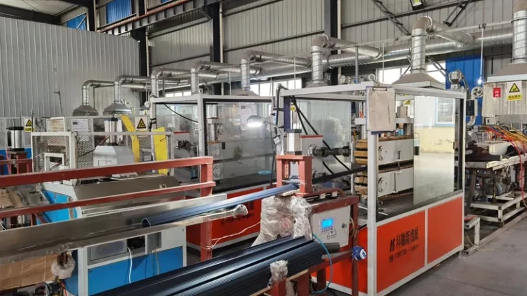
Every multi-layer plastic profile is won or lost at the die head. The extruders can be correctly sized and the calibrator expertly cut, but if two or three melts are not merged into stable, correctly proportioned layers inside the die head, no downstream adjustment rescues the run. This guide explains how co-extrusion die heads work, when a feedblock beats a multi-manifold design, which material combinations are proven, and what tolerances to expect when buying profile extrusion services.
- The die head, not the extruder or the calibrator, decides layer order, layer thickness and boundary stability in a multi-layer profile.
- Feedblock tooling is compact and cheaper to modify; multi-manifold die heads give independent control of every layer at higher tooling cost.
- Proven pairs such as PP+TPV, PVC+TPU and ABS+TPU combine a rigid core with a soft, low-friction or weatherable skin.
- Layer ratios are engineered into the die, verified on first articles, then held through melt pressure and temperature stability.
- Total cross-section tolerance includes every layer, so soft-skin profiles need per-layer targets, not just an overall dimension.
How Does a Multi-Layer Co-Extrusion Die Head Work?
A co-extrusion die head takes separate polymer melts from individual extruders and merges them inside the tool so they leave the die lips as one profile with fixed layer boundaries. Each extruder meters its own layer, and the internal flow channels distribute the combined melt into the final cross-section before it reaches the vacuum calibrator.
Two architectures dominate profile extrusion. In a feedblock system, the melts are stacked into a single laminate in a compact block ahead of a conventional single-manifold die, which keeps tooling simple and makes layer-order changes relatively quick. In a multi-manifold die head, each material has its own manifold and restrictor inside the die body, and the layers meet only shortly before the die exit, giving every layer an adjustable channel of its own.
Both architectures rely on the same physics: the melts stay in laminar layers, and their viscosity1 must be close enough at die temperature that neither layer races ahead or stalls at the interface. Large mismatches appear immediately as interfacial waves. Residence time is the second constraint — a soft TPV or TPE skin tolerates a narrower thermal window than a rigid PP or PVC core, so the skin’s flow path must be short and free of stagnation zones.
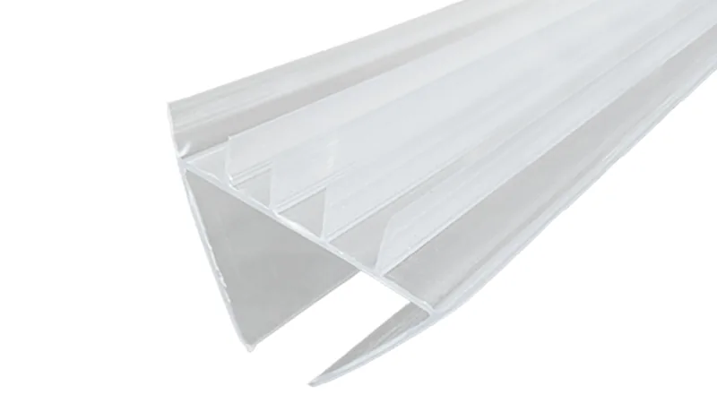
Layer order is fixed by channel geometry, not by extruder speed alone. Speeds meter how much of each material arrives; the manifolds decide where it ends up. That is why a die head for an extruded profile is quoted and built for one defined layer stack, and why changing the stack usually means new tooling rather than new settings.
"A feedblock and a multi-manifold die head are interchangeable, so the cheaper tooling always wins."False
The two architectures merge layers at different points with different flow control. A feedblock limits per-layer correction, while a multi-manifold die head lets each layer be tuned independently — so the wrong choice surfaces as off-ratio layers that no process window can trim back.
"The feedblock versus multi-manifold choice should follow the material pair and the layer stack."True
Two melts with similar viscosity and a simple skin-over-core section run economically in a feedblock. Unequal viscosities, thin functional skins or layers that must stay centered inside the section favor multi-manifold tooling, where each channel is adjusted on its own.
Feedblock or Multi-Manifold Die Head: Which Layout Fits?
Use the section drawing, not the price list, to decide the layout. The comparison below summarizes where each design pays off:
| Criterion | Feedblock + single manifold | Multi-manifold die head |
|---|---|---|
| Tooling cost and lead time | Lower; block and die are separate parts | Higher; channels machined into one die body |
| Per-layer adjustment | Limited; one restrictor shapes the merged laminate | Independent restrictors per layer |
| Viscosity mismatch tolerance | Narrow; layers merge early and can distort | Wider; layers meet near the die exit |
| Thin functional skins | Hard to hold consistently | Practical with dedicated metering |
| Layer order changes | Fast; swap or re-plumb the feedblock | Slow; usually means new tooling |
| Best fit | Simple skin-over-core sections | Sealing lips, encapsulated or centered layers |
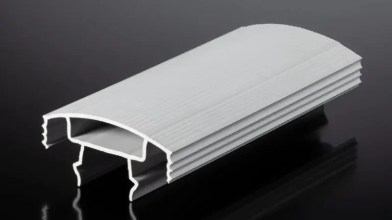
A soft cap laid flat over a rigid core is the classic feedblock job. When the soft layer forms a sealing lip, wraps a corner or must sit at a defined depth inside the section, a multi-manifold die head is the safer engineering choice even though it costs more up front, because the alternative is fighting layer position with process settings for the life of the tool.
ZetarVac runs single, double and triple layer extrusion including up to three layers of co-extrusion in a single pass, with combinations actually in production such as PP+TPV, PP+TPE, PVC+TPU, ABS+TPU and TPV+CPVC. If your layer stack matches one of these proven pairs, the melt behavior is already characterized on the line, which lowers tooling risk.
Which Layer Combinations Work in Practice?
The proven pattern is a rigid structural layer paired with a soft or weatherable functional skin: PP+TPV and PP+TPE for sealing and gasketing, ABS+TPU for flexible wiping edges, and PVC+TPU where a rigid PVC body needs a resilient contact surface. The rigid layer carries structure; the skin supplies what it cannot.
The rigid layer is chosen for structure and cost — PVC, ABS, PP, HDPE, PC/ABS or PA6 depending on the application — while the cap layer adds low friction, sealing, abrasion resistance or weatherability. For outdoor building profiles, an ASA or TPV cap protects the core, and outdoor durability claims are backed by exposure testing under ISO 4892, which specifies how plastics are exposed to laboratory light sources to simulate long-term weathering.
Adhesion between layers is usually mechanical rather than purely chemical in profile extrusion. Because the section is shaped, the die can be designed so the soft layer keys into grooves or wraps the edges of the rigid core, which is more robust than relying on melt compatibility alone. Chemically related pairs such as PP with TPE or TPV knit more readily, and the die head temperature profile is tuned to keep both melts hot enough to knit but not hot enough to degrade the skin.
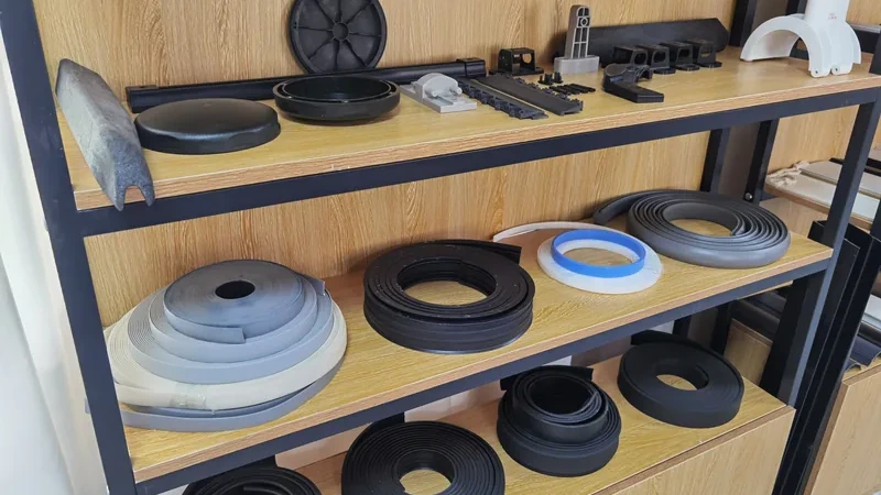
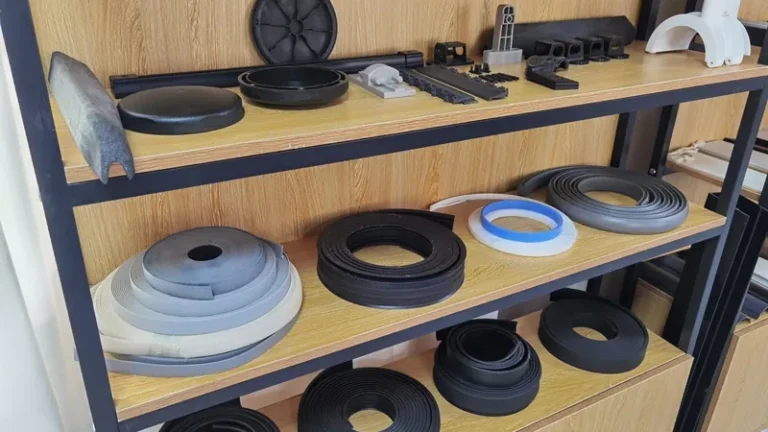
Two running examples show the logic. An automotive seat slide rail strip in PP+TPV uses the rigid PP for structural support in the seat rail and guide system, while the TPV forms a flexible sealing lip combining dust exclusion, low friction and wear resistance. A robot vacuum squeegee strip in ABS+TPU applies the same logic in miniature: ABS gives the rigid backing, TPU the flexible, abrasion-tolerant wiping contact. In both cases co-extrusion exists because no single material delivers the combination.
Both of these co-extrusion parts run as production cases: the PP+TPV automotive seat slide rail strip and the ABS+TPU robot vacuum squeegee strip. For a buyer, that means these material pairs can be discussed against real production experience rather than datasheet values alone.
What Goes Wrong First in a Co-Extrusion Die Head?
Layer imbalance, interfacial instability and skin encapsulation appear first, and all three originate at the die head rather than downstream. When layers drift out of ratio or the soft skin migrates, correct melt temperatures, pressures and flow channels at the die before touching the calibrator.
Layer ratio drift comes from the melt side. Melt pressure and temperature at each extruder fluctuate with screw condition, barrel wear and regrind ratio, and the die head converts every fluctuation into layer thickness. The check is direct: cut cross-sections at defined intervals and measure each layer, or weigh separated layers against the total. Drift that tracks a pressure reading points at the melt system; stable pressure with drifting layers points at the die head itself.
Interfacial instability shows as regular waves or blurring at the layer boundary, caused by viscosity mismatch or excessive shear where the layers meet. Correct it in order: bring layer temperatures toward each other, reduce total output slightly, then rework internal flow lengths. Left alone, the boundary wanders, and with it the thickness of the functional skin you are paying for.
Encapsulation2 is the slow failure mode: a lower-viscosity layer gradually wraps the higher-viscosity core and creeps over surfaces that belong to the core, often appearing well into the run rather than at start-up. Die head design counters it with a late merge point, balanced flow lengths and streamlined channels without dead spots; operating discipline counters it with defined purge and shutdown procedures.
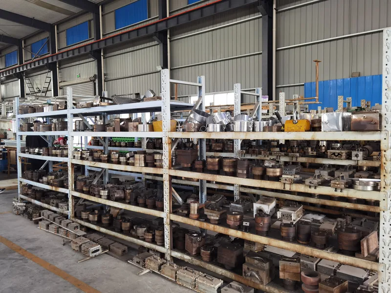
Die lines and dark streaks usually mean stagnation. A co-extrusion die head carries more internal surface than a single-layer tool, and any corner where melt sits too long carbonizes and eventually streaks the extruded profile. Streamlined manifolds, scheduled purging and periodic die head disassembly keep this in check, which is why maintenance intervals belong in the tooling discussion, not only in the quotation price.
What Tolerances Can a Multi-Layer Profile Realistically Hold?
Total cross-section tolerance covers all layers together. ZetarVac commits to a minimum achievable tolerance of ±0.05 mm on the profile cross-section, subject to material and section geometry. Treat that as a capability floor set by tooling and measurement discipline, not as a blanket promise for every layer of every section, and expect the achievable value to be confirmed during tooling tryout.
Every layer adds a tolerance contribution. The rigid core behaves like a conventional profile, but soft TPE and TPV skins shrink and relax more as they cool, so a sealing lip measured straight at the die exit will not match the same lip once it has fully cooled and relaxed. Place functional dimensions on the rigid structure where possible and treat soft-layer dimensions as process windows verified by measurement rather than drawing absolutes.
Material standards frame what the die head must deliver. For PVC-U window and door profiles, EN 12608 specifies the profile geometry, impact resistance and heat reversion requirements the finished profile must meet, so a co-extruded cap layer cannot change the outside dimensions that the standard fixes3. Thermal history picked up in the die head also shows up measurably in the part through indicators such as the Vicat softening temperature defined in ISO 3064.
"Once the first article is approved, the co-extruded profile will hold tolerance for the whole run."False
A first article samples one moment of a drifting process. Melt temperature, pressure and ambient conditions move over a shift, so layer ratios and overall dimensions need scheduled cross-section checks and melt pressure records to demonstrate stability.
"Layer ratio stability is proven by cross-section sampling across the production run."True
Sections cut and measured at defined intervals catch layer drift while it can still be corrected. Logged against the melt pressure and temperature records from each extruder, the sampling history shows whether the die head holds what the first article promised.
How Should You Prepare Drawings for a Co-Extrusion Die Head Review?
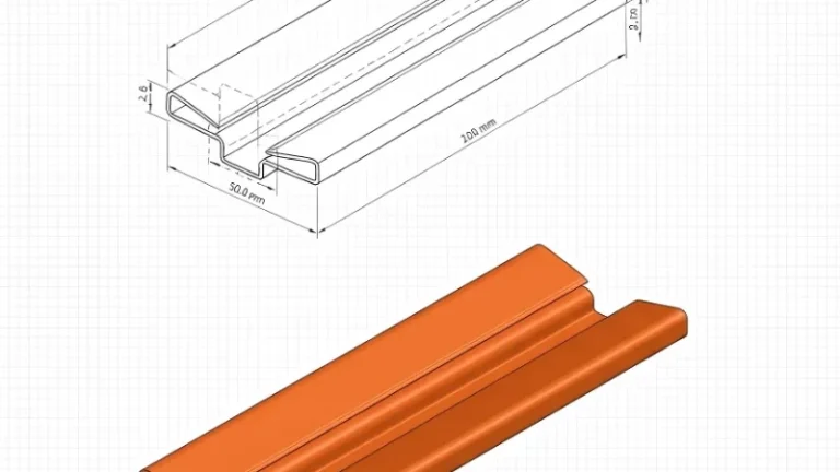
Submit the complete cross-section with total and per-layer thickness targets, the material designation for every layer, the tolerance class and the service environment. Mark which surfaces are functional — sealing lips, sliding faces, snap features — so the die designer can concentrate precision where it earns its cost.
A die head is built for one layer stack, so ambiguity in the drawing becomes cost in the tool. Uniform wall thicknesses, generous radii and realistic soft-layer proportions shorten the tryout loop. The die head design guide explains how channel geometry, merge point and restrictor settings are chosen, and the DFM checklist for extruded profiles and extrusion dies lists the drawing details reviewers look for first; the profile extrusion cost breakdown shows how tooling structure and layer count move the budget.
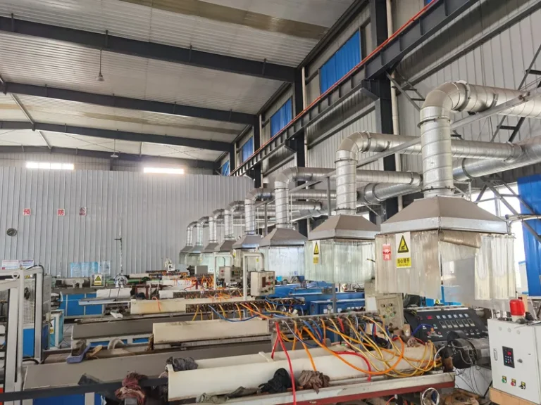
ZetarVac runs 7+ automated extrusion lines with a maximum profile width of 600 mm, within a plant of 45+ production lines, supporting prototyping, small batch and large batch production with a reference monthly capacity of about 300–500 tonnes on the extrusion lines. In-line punching, embossing and printing can be added downstream of co-extrusion, reducing secondary handling.
FAQ
How many layers can one co-extrusion pass deliver?
For profile extrusion, two to three layers is the practical range, and that matches how tooling is built. ZetarVac runs up to three layers in a single co-extrusion pass, with foam extrusion available as a separate mode for sections that need it.
Can unrelated plastics be co-extruded without a tie layer?
Often yes in profiles, because section geometry provides a mechanical lock that the melts alone would not achieve. Chemically related pairs such as PP with TPV knit naturally, while unrelated pairs rely more on the interlock designed into the die head, which the tooling review should confirm before steel is cut.
Does the soft skin count toward the overall profile tolerance?
Yes. Overall cross-section dimensions include every layer, so variation in the soft skin consumes part of the total tolerance budget. Drawings for co-extruded profiles should carry both an overall dimension and per-layer targets, with the tightest tolerances placed on stable rigid sections.
What information speeds up a die head quotation?
A dimensioned cross-section, the material designation for each layer, target layer ratios, tolerance class, annual volume and service environment. With those inputs, a supplier can decide between feedblock and multi-manifold tooling and flag viscosity or thermal conflicts before cutting steel.
How is a co-extruded profile inspected in production?
By periodic cross-section sampling: cut a slice, measure total and per-layer dimensions under magnification, and log results against melt pressure records. Surface-critical profiles add visual checks for die lines, and functional lips are measured after cooling and relaxation are complete.
If you are comparing suppliers for a multi-layer profile, the useful next step is technical rather than commercial: send your drawings and layer stack for review, or talk to an engineer about whether your section suits feedblock or multi-manifold tooling. You can evaluate ZetarVac’s extrusion capabilities or review the full service range to start that conversation.
-
Melt flow index: Melt flow index measures how easily a molten polymer flows under a fixed load and is commonly used to compare and match viscosity between co-extruded layers. ↩
-
Encapsulation: In co-extrusion, encapsulation is the tendency of a lower-viscosity melt layer to migrate toward channel walls and wrap around higher-viscosity layers during flow. ↩
-
EN 12608: EN 12608 is the European standard for unplasticized PVC (PVC-U) profiles for windows and doors, covering profile geometry, impact resistance and heat reversion. ↩
-
Vicat softening temperature: The Vicat softening temperature is the temperature at which a flat-ended needle indents a thermoplastic specimen to a defined depth under load, used as a heat resistance indicator. ↩