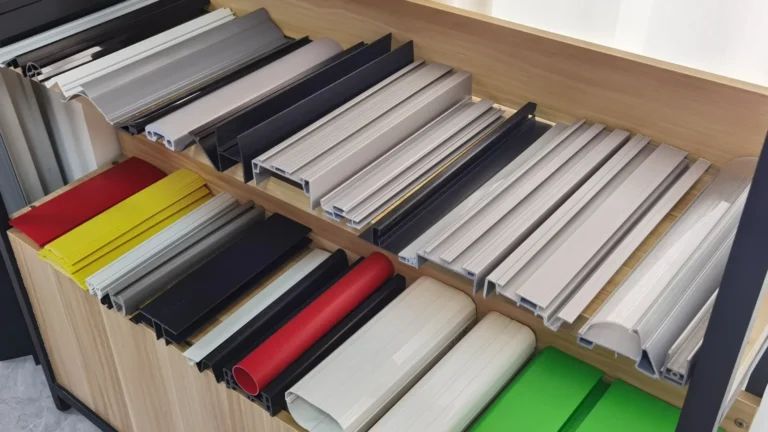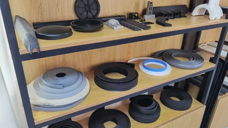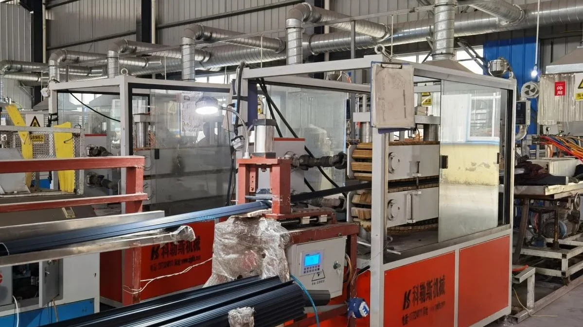
Every profile extrusion line makes scrap. The difference between a profitable line and a struggling one is how fast the crew can read a symptom, isolate the zone that produced it, and apply one corrective change instead of five guesses. This guide covers the defects that account for most downtime on profile lines — dimensional drift, warpage, die lines, melt fracture, gels and surging — and the first corrective actions process engineers reach for in each case.
The same logic applies across materials from rigid PVC to TPU and across single-layer and co-extruded sections. Where numbers appear, treat them as conventional engineering ranges that depend on material, section geometry and equipment, not as universal setpoints.
- Most extrusion defects trace back to four variables: melt temperature, die condition, cooling and vacuum calibration, and haul-off stability.
- Dimensional drift after start-up is usually a thermal equilibrium problem, not a die problem; stabilise the process before cutting steel.
- Surface defects point to different zones: die lines to the die land, gels to the barrel or screen pack, melt fracture to excessive shear at the die exit.
- Troubleshooting works best one variable at a time, with baseline settings recorded before every change.
- A passing first article does not guarantee production stability; capability comes from documented start-up routines and periodic section measurement.
Where Extrusion Defects Actually Come From
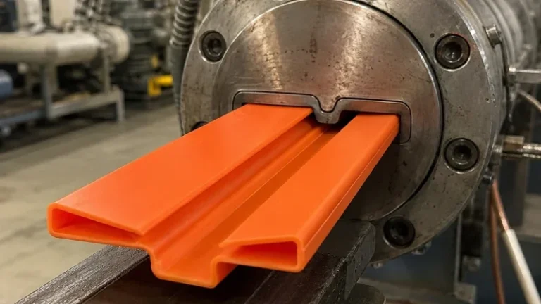
A profile extrusion line is a chain of thermal and mechanical stages: the extruder melts and pressurises the polymer, the die head shapes it, a vacuum calibrator and water bath fix the dimensions, and the haul-off draws the profile at a controlled speed. A defect can originate in any stage, but the symptom usually appears downstream of the cause, which is what makes diagnosis non-obvious.
Material behaviour adds a second layer. Rigid PVC, for instance, is judged against standards such as EN 12608, which specifies profile geometry, impact resistance and heat reversion for PVC-U window and door profiles — meaning that dimensional stability after extrusion is a specification requirement, not just a cosmetic preference.
Because the symptom usually sits one or two stages away from the cause, it helps to keep the full process picture in view; the plastic extrusion molding guide maps each line stage from extruder to haul-off.
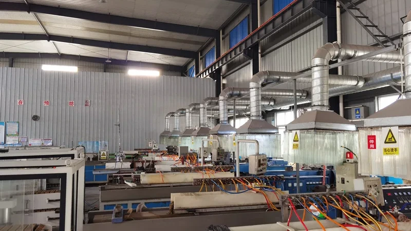
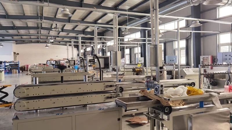
ZetarVac runs more than seven automated extrusion lines with a maximum profile width of 600 mm and in-line punching, embossing and printing. In-line secondary operations add failure modes of their own — punch misalignment and print drift are downstream symptoms that still require upstream process correction.
Why Does Profile Dimension Drift After Start-Up?
Dimensional drift is mostly a thermal equilibrium problem: the die, calibrator and cooling water have not reached steady state, so shrinkage and drawdown keep changing over the first tens of metres of output. Stabilise temperatures and haul-off speed first; most drift disappears without touching the die.
The first variable is drawdown1. Haul-off speed relative to melt exit velocity stretches or relaxes the profile, and every material has a workable drawdown ratio window. Push beyond it and the profile thins unevenly, internal stress rises, and dimensions start walking as melt temperature wanders. Design the die so the line runs near the middle of its drawdown window, not at the edge where small speed changes become visible dimension changes.
The second variable is vacuum sizing2. Vacuum in the calibrator presses the hot extrudate against a water-cooled sleeve; too little vacuum leaves the profile oversize with soft corners, too much drags and scores the surface. Conventional practice tunes each calibrator chamber separately and watches for the profile sitting consistently against the sleeve rather than oscillating between chambers.
Warpage usually comes from asymmetric cooling. A thick wall on one side shrinks more than a thin wall opposite it after exit, so the profile bows toward the heavy section even when it measured straight in the calibrator. The countermeasures are zoning the cooling water, balancing wall sections in the design phase, and checking straightness again after the profile has fully cooled — not only at the line.
"Profile tolerances are controlled by the extrusion die alone."False
The die sets the cross-section geometry, but drawdown, vacuum calibration and haul-off speed determine the final dimensions. A line that cannot hold tolerance often has a downstream problem, and cutting a new die changes nothing.
"Final profile dimensions depend on die, calibration and haul-off together."True
Tolerances in the ±0.05 mm class are only sustainable when the whole line is thermally stable. Before any tooling change, verify calibrator vacuum, water temperatures and haul-off speed consistency.
Measure at a fixed distance from start-up, because dimensions in the first metres reflect a transient state. Laser scanning or cut sections taken every few metres during stabilisation show whether the line has genuinely reached equilibrium. Judging a setting change on dimensions sampled too early produces false conclusions and wasted die modifications.
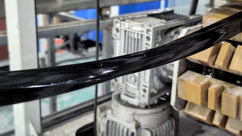
On modern lines, cross-section tolerances down to ±0.05 mm are achievable across profile widths from 5 to 600 mm, subject to material and section geometry. That accuracy only holds when vacuum calibration and haul-off speed stay stable, which makes tolerance capability a line-level property rather than a die-level one.
What Causes Surface Defects Like Die Lines and Melt Fracture?
Die lines come from the die land — damage, wear or degraded build-up — while melt fracture is a flow instability triggered when shear stress at the die exit exceeds a critical level. Gels and discolouration trace back to material degradation in the barrel or contaminated regrind.
Die lines run lengthwise and copy the land: a scratch, wear ring or deposit stretches the defect down the profile. Plate-out3 — additive residues building up on metal surfaces — is the common culprit on PVC and filled compounds, and it appears gradually after hours of running. Purging, polishing or refinishing the land and reviewing the additive package are the standard responses.
Melt fracture4 looks different: sharkskin roughness or regular distortion at the exit rather than a clean streak. It appears when shear stress at the exit exceeds a critical level, typically at high line speed, low melt temperature or an abrupt die exit geometry. Raising melt temperature within the material limit, slowing the line, or streamlining the die exit are the first moves.
Gels and discolouration point back into the barrel. Excessive residence time, overheated rear zones or degraded regrind release small unmelted or burnt particles that survive the screen pack and land in the surface. Check screen pack condition, audit regrind ratio and cleanliness, and shorten residence time before blaming the die.
When a surface defect raises doubt about mechanical integrity, the standard verification is tensile testing to ASTM D638, which defines the test method for tensile properties of plastics and is the default citation for extruded profiles5. A visual defect and a strength failure are separate verdicts; testing keeps the two apart.
"Melt fracture means the resin is defective."False
Melt fracture is a flow instability that appears when shear stress at the die exit exceeds a critical level. Raising melt temperature within the material limit, lowering line speed or streamlining the die exit normally removes it without touching the material.
"Melt fracture is a process condition before it is a material problem."True
The same resin can run cleanly at a lower shear rate. Confirm the temperature profile and speed window first, and only reject the compound after clean processing conditions fail.
Co-extruded sections add one more diagnostic layer: the interface. Delamination, layer wave or an unbalanced skin thickness can come from either extruder, the layer ratio or the co-extrusion die head design, and the fix differs accordingly. The article on co-extrusion die heads and multi-layer profiles covers how layer distribution is engineered and where those defects form.
Co-extrusion up to three layers in a single pass — with combinations actually running such as PP+TPV, PVC+TPU and ABS+TPU — means a surface defect may belong to either layer or to the interface. Layer thickness ratio and adhesion become additional diagnostic variables on top of the usual list.
How Should a Troubleshooting Sequence Be Structured?
Work one variable at a time, from the melt backwards: confirm material condition and moisture, check melt temperature and pressure, inspect the screen pack and die, then move to vacuum, cooling water and haul-off. Record the baseline before every change so the effect of each adjustment is measurable.
Baseline discipline comes first. Record every setpoint — zone temperatures, screw speed, vacuum levels, water temperatures, haul-off speed — before touching anything. Without a documented baseline, a change that helps one defect can quietly create another, and the crew ends up chasing its own adjustments.
Start with the material. Moisture above the material limit produces bubbles and voids that mimic other defects; an inconsistent regrind ratio shifts melt viscosity and with it every dimension. Verify drying and regrind consistency before adjusting any heater zone, because the cheapest fix is usually upstream of the extruder.
Next, confirm the melt state. Zone temperatures set within the material window, stable melt pressure and a clean screen pack are preconditions for every downstream adjustment. Periodic surging — size waves at a regular frequency — usually indicates feed instability or screw wear rather than a calibration problem.
Only then move downstream. Tune calibrator vacuum chamber by chamber, set water zones so the profile exits cool enough to hold shape, and verify haul-off belt grip and speed stability. Slipping belts leave a characteristic waviness that no die change will ever fix.
The table below condenses the most frequent defects into an origin zone and a first corrective action:
| Defect | Usual origin zone | First corrective action |
|---|---|---|
| Dimensional drift | Thermal non-equilibrium | Stabilise die and calibrator temperatures; verify haul-off speed |
| Warpage | Asymmetric cooling | Rebalance water zones and calibrator vacuum; review section symmetry |
| Die lines | Die land | Inspect, polish or refurbish the die; purge degraded build-up |
| Melt fracture | Excess shear at die exit | Raise melt temperature within limits or reduce line speed |
| Gels, discolouration | Barrel, screen pack, regrind | Check screen pack; shorten residence time; audit regrind |
| Surging | Melt pressure instability | Verify feed and heater zones; check screw wear |
| Bubbles or voids | Moisture or volatiles | Dry the material and verify moisture before extrusion |
| Waviness | Haul-off slippage | Check belt pressure and grip; synchronise haul-off speed |
For deeper case material, the SPE Extrusion Division maintains technical resources on extrusion troubleshooting that follow exactly this zone-by-zone logic.
Which Checks Separate a Good First Article From Stable Production?
A first article proves the tooling can produce the section; it does not prove the line can repeat it. Production stability shows up in three places: the trend of start-up scrap across runs, section measurements at fixed intervals during a shift, and consistency across material lots. When you compare suppliers, ask to see those records rather than a single sample.
"Once the first article passes, production will hold tolerance."False
A first article is a snapshot taken at thermal equilibrium after a controlled start-up. Long-run drift, material lot variation and die wear appear over hours, not minutes, so a single passing sample proves very little about capability.
"Long-run capability needs documented start-up routines and periodic section checks."True
Stable producers measure sections at fixed intervals, log process settings per material and track start-up scrap as a trend. That record, not one sample, is what demonstrates a repeatable process.
Documentation is what makes stability transferable. A process sheet per material and section — temperatures, vacuum, speeds and the approved start-up sequence — lets a second shift or a second line reproduce the result. Lines without documented routines routinely show wide run-to-run variation on identical tooling.
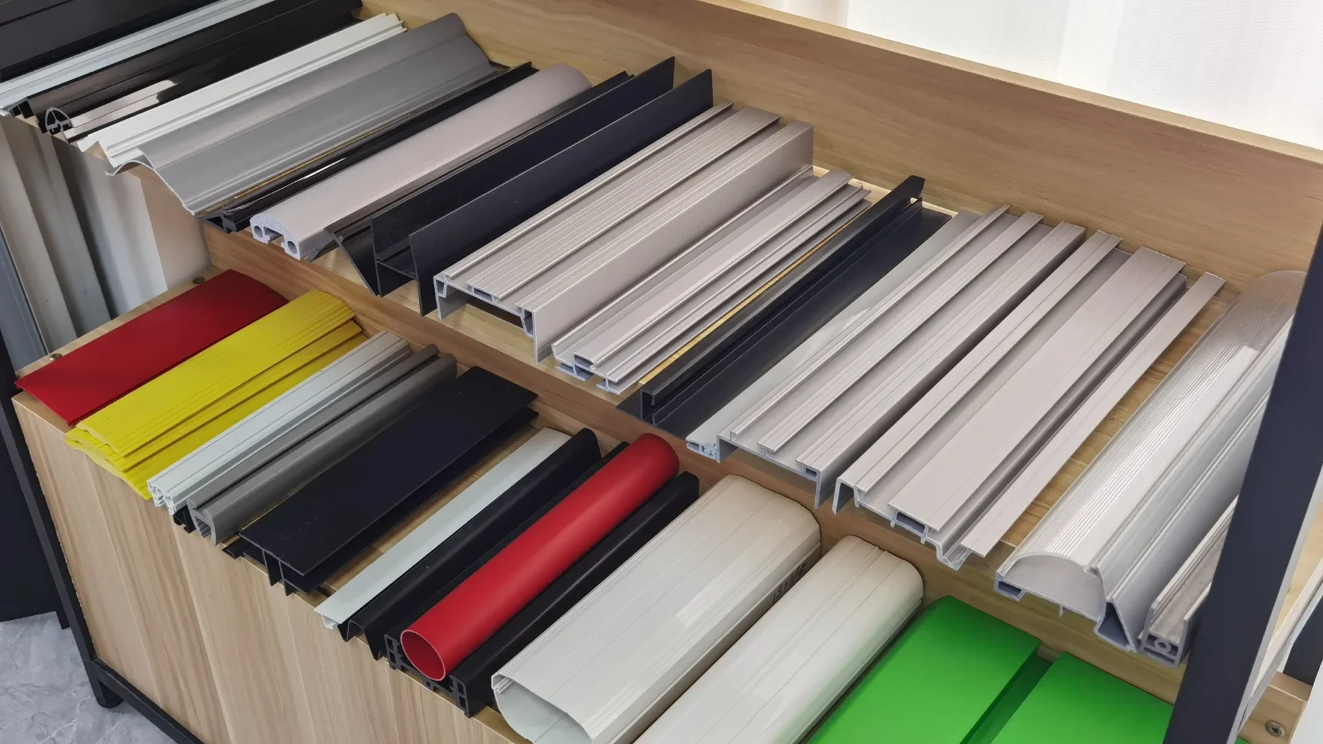
When you are ready to compare suppliers on this basis, a capable profile extrusion partner should describe its start-up routine, tolerance verification and in-line operations without prompting; ZetarVac’s custom profile extrusion capabilities page lists line count, width range and in-line punching, embossing and printing.
FAQ
What is the fastest way to tell a die problem from a downstream problem?
Cut the extrudate right at the die exit, before it reaches the calibrator. If the defect is already present in the hot melt, look upstream at the die and extruder; if the hot profile is clean but the finished profile is defective, the calibrator, water bath or haul-off is the cause.
How much start-up scrap is normal on a profile extrusion line?
It depends on material and section complexity, but a conventional expectation is that a stable line reaches dimension within a few metres to a few tens of metres of start-up. Scrap that continues beyond the first run length usually signals an unstable process window rather than normal start-up loss.
Can a co-extrusion defect be fixed without changing the die?
Often yes. Layer ratio, melt temperatures and output balance are adjustable per extruder, so many interface defects — delamination, layer wave, unbalanced skin — are corrected through process settings. Persistent layer imbalance or poor adhesion across all settings, however, points to die head design or material compatibility.
When should a defect trigger die refurbishment instead of another process change?
When the same symptom returns after confirmed process adjustments — a die line that reappears after purging, or a dimension that cannot be pulled into tolerance without extreme drawdown — the die land or calibrator is likely worn. Polish, rework or replace the tooling rather than compensating with a distorted process window.
If you are evaluating options for a new or problem profile, send your drawings for an engineering review: ZetarVac’s team can assess cross-sections, tolerances and material choices — start from its plastic extrusion manufacturer page or browse the full service range.
-
Drawdown: The ratio between the die opening and the final profile dimensions, created when haul-off speed exceeds the melt exit velocity. ↩
-
Vacuum sizing tank: A calibrator that uses applied vacuum to press the hot extrudate against a water-cooled sleeve, fixing the outer dimensions. ↩
-
Plate-out: The gradual build-up of additive residues on die and calibrator surfaces, which produces streaks and slow dimensional drift. ↩
-
Melt fracture: A flow instability that creates rough or distorted surfaces when shear stress at the die exit exceeds a critical level. ↩
-
ASTM D638: The standard test method for tensile properties of plastics, commonly cited to verify the mechanical strength of extruded profiles. ↩