Most buyers judge an extrusion line by its die head and downstream equipment, and discover too late that the real constraint sits one step upstream. The extrusion screw performs the solids conveying, melting, and metering that everything downstream depends on, and no sizing sleeve can rescue an unstable melt. This guide covers the main screw types, the polymers each design suits, the failure modes a mismatch produces, and the questions worth asking a supplier before you release a profile program.
- The extrusion screw does three jobs at once — solids conveying, melting, and metering — and output stability depends on all three staying in balance.
- Single-flight, barrier, mixing, vented, and grooved-feed screws each solve a different melting problem; matching design to polymer matters more than chasing line speed.
- Barrier and mixing sections reduce melt temperature variation, which is the same variation that later appears as dimensional drift on an extruded profile.
- Vented two-stage screws are the default answer for regrind content and moisture-sensitive compounds such as TPE and TPU.
- Screw geometry — diameter, L/D ratio, and compression ratio — belongs on your drawing-level supplier checklist, not buried as an internal detail.
- A passing first article does not prove process capability; sustained dimensional stability over a full production run does.
Why the Screw Sets the Ceiling on Profile Quality
Inside the barrel, the screw is a continuous reactor. The feed zone conveys pellets, the compression zone melts and pressurizes them, and the metering zone delivers a constant flow at constant temperature. Whatever variation the screw introduces — a pressure pulse, a temperature swing of a few degrees — travels through the extrusion die and appears as wall-thickness variation, sink, or wave in the finished section. Vacuum sizing corrects geometry; it cannot correct an unstable melt. For the wider process from pellets to finished sections, see our overview of plastic extrusion molding.
That is why tolerance conversations should start at the screw. A supplier who commits to ±0.05 mm on a profile cross-section — achievable depending on material and section geometry — is implicitly committing to a melt stream stable enough for the die head to work with. When melt pressure oscillates, the die flows more or less material second by second; when melt temperature drifts, viscosity drifts with it, and so does drawdown into the sizing sleeve. Both problems originate at the screw, and both are fixed there.
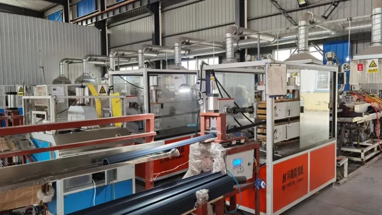
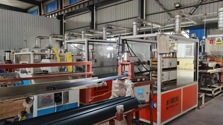
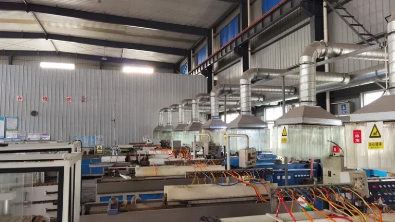
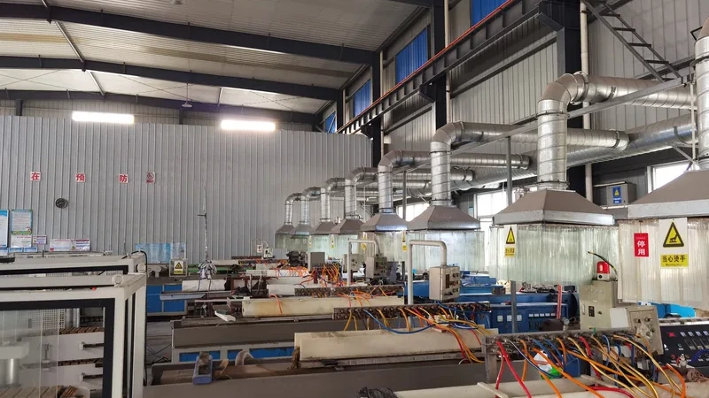
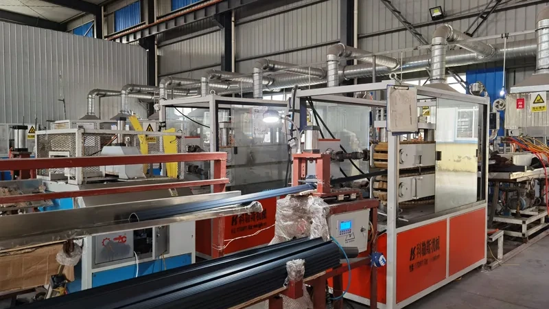
ZetarVac runs more than seven automated extrusion lines with a maximum profile width of 600 mm and in-line punching, embossing, and printing. In-line secondary operations amplify upstream instability: a line that surges at the screw punches, embosses, and prints a moving target. Melt stability is the precondition for those operations to hold position.
What Are the Main Types of Extrusion Screws?
The main types are the single-flight general-purpose screw, barrier screws, mixing screws, vented two-stage screws, and grooved-feed screws. Each targets a specific stage of melting: barrier flights separate solid bed from melt, mixing sections homogenize temperature and additives, vented screws extract moisture and volatiles, and grooved feed raises conveying efficiency for slippery polymers.
The single-flight screw remains the workhorse of profile extrusion. Its three zones are proportioned by the compression ratio1, and it is predictable, forgiving, and economical. Its weakness is melting rate: late in the compression zone the solid bed breaks up, and unmelted fragments can pass into metering, producing temperature nonuniformity exactly when throughput rises.
Barrier screws answer that weakness with a secondary barrier flight2 that splits the channel into a solids channel and a melt channel. The barrier flight is undercut so only melted material crosses it, forcing the solid bed to melt out at a consistent position instead of breaking apart unpredictably. The result is a more uniform melt at higher specific output, which is why barrier designs dominate high-rate polyolefin and ABS work.
Mixing, venting, and grooved feed each add a specific capability. Maddock and distributive mixing sections homogenize melt temperature and disperse additives, colorants, and flame-retardant packages. Vented two-stage screws add a decompression zone under a vacuum port that pulls moisture and volatiles from the melt — the standard answer where regrind content makes dryer upsets a production risk. Grooved feed sections grip slippery HDPE and PP pellets in the feed throat, stabilizing output at high line speed.
"A larger screw diameter automatically means higher usable output for my profile."False
Output is capped by melting rate and melt stability, not by metal displacement. An oversized screw running a melting-limited material will surge or overheat, and usable output can actually fall. You pay for capacity the process cannot convert.
"Output stability comes from matching screw geometry to the polymer, not diameter alone."True
A correctly proportioned screw melts at a consistent rate and feeds the die head a steady pressure signal, which is what lets the rest of the line hold dimension. Diameter sets the envelope; geometry decides whether it is usable.
How Do Barrier and Mixing Sections Change Melt Quality?
Barrier and mixing sections control the two properties that matter most downstream: melt temperature uniformity and additive dispersion. They rarely raise peak output by much; they reduce the variation around the average, which is what tolerance-critical profile work actually needs.
Temperature uniformity matters because profile dies are flow-balanced around a design viscosity. A melt that enters the extrusion die a few degrees hotter than assumed flows differently through each land, thinning some walls and thickening others. On multi-layer parts the effect compounds: the automotive seat slide rail strip ZetarVac produces as a PP+TPV co-extrusion pairs a rigid PP carrier with a flexible TPV sealing lip, and each layer must arrive at the die head with stable temperature and pressure for that lip to sit where the drawing puts it.
Mixing quality is just as measurable. A compound that must carry a UL 94 flammability rating3 — the standard that classifies how plastic materials for parts in devices and appliances burn — depends on the flame-retardant package being dispersed uniformly through the melt. Poor mixing shows up not as a visual defect but as burn-test scatter between production lots, which is the expensive way to find out.
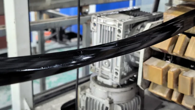
For multi-layer sections, the screw and the co-extrusion die head must be specified together, because layer stability starts in each screw and only meets in the tooling. Our overview of co-extrusion die head design for multi-layer profiles walks through that interface.
Which Screw Should You Specify for Your Material?
Rigid PVC wants low-shear, streamlined flow paths; polyolefins reward grooved feed and barrier sections; engineering resins such as PA6, POM, and PC need tight temperature control and often venting; soft TPE and TPU compounds need gentle shear to avoid overheating. The screw is specified for the polymer, never the reverse.
Rigid PVC is the clearest case. ISO 11634 governs the designation and specification of unplasticized PVC moulding and extrusion materials, so the melt-flow and mechanical envelope your profile must meet is defined at the compound level — and the screw has to deliver that compound without pushing it past its thermal window. PVC degrades quickly when over-sheared, which is why PVC screws favor deeper channels, lower compression, and streamlined transition geometry over aggressive high-shear designs.
Polyolefins run the other way: HDPE and PP melt gradually and convey poorly in smooth-bore feed sections, which is why grooved feed plus a barrier or mixing section is the standard high-rate combination. Engineering resins sit in between. PA6, PA66, POM, and PC melt cleanly but are sensitive to moisture and residence time, so vented screws and generous L/D ratios5 are common where these materials run into precision profiles and mechanical parts.
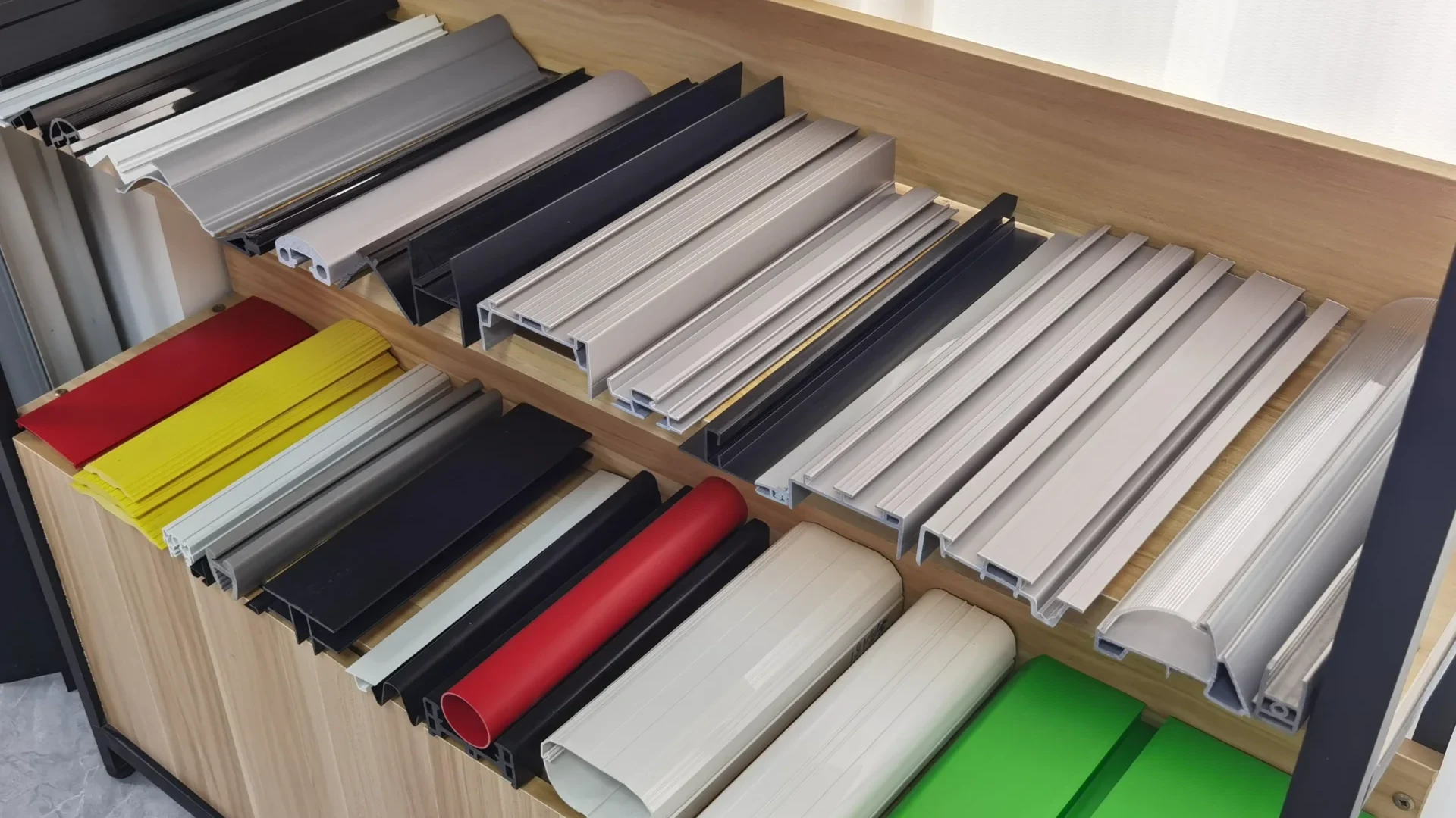
ZetarVac’s material library spans PVC, ABS, HDPE, LDPE, PP, PC, PMMA, PA6/PA66, POM, TPE, TPU, TPV, PC/ABS, ASA, and PP/GF, with co-extrusion combinations such as PP+TPV, PP+TPE, PVC+TPU, ABS+TPU, and TPV+CPVC in production. Each material stream in a multi-layer part has its own melt-stability requirement, so screw selection is made per layer, not per line.
| Screw type | Best suited materials | Main benefit | Watch-outs |
|---|---|---|---|
| Single-flight general purpose | Rigid PVC, general profiles | Predictable, forgiving, economical | Temperature nonuniformity at high throughput |
| Barrier screw | PP, HDPE, ABS, regrind blends | Consistent, complete melting | Higher shear; heat-sensitive PVC needs low-shear geometry |
| Mixing section | Additive and flame-rated compounds | Uniform temperature and dispersion | Added pressure drop; consumes L/D budget |
| Vented two-stage | Regrind, PA, moisture-prone TPU | Removes moisture and volatiles | Lower output per revolution; vent maintenance |
| Grooved feed | HDPE, PP, slippery resins | Stable high-rate conveying | Higher wear and drive load |
The table is a starting map, not a substitute for a melt-flow review: the same material can justify different geometry at different outputs and section complexities. When in doubt, ask which screw runs your material today and what dimensional data that combination produces.
"A general-purpose screw runs every polymer equally well."False
Rigid PVC, polyolefins, and engineering resins differ in melting range, viscosity, and shear sensitivity. One compromise geometry over-shears PVC and under-melts HDPE, and both mistakes surface as dimensional scatter on the finished profile.
"Screw geometry must be matched to each polymer family's melting behavior."True
Compression ratio, flight depth, and shear history decide whether a compound melts fully without overheating. Matching geometry to the material is the cheapest dimensional-stability investment available on an extrusion line.
What Goes Wrong When the Screw and the Job Are Mismatched?
The classic symptoms are surging — periodic output oscillation — plus unmelted pellets in the melt stream, discoloration from overheated stagnant material, and dimensional drift that no die adjustment tunes out. All four trace back to screw geometry that does not fit the material or the throughput the line is asked to run.
Surging is the most common. When melting capacity runs out ahead of conveying capacity, the solid bed breaks unevenly and the metering zone alternately starves and floods; output oscillates with a period you can time with a stopwatch, and the profile walls breathe with it. If the symptom scales with line speed and disappears when you slow down, suspect the screw before the die.
Degradation is the second family. Long residence time in a poorly matched screw scorches PVC, yellows PC, and darkens ABS, typically worst in stagnant corners behind worn flights. Because these defects build over hours of running, they rarely appear on a first article — they appear in lot two. Our guide to common extrusion defects and troubleshooting maps these symptoms to their upstream causes.
"A passing first article proves the screw and process are production-ready."False
A first article is one snapshot taken under trial conditions. Surging, residence-time degradation, and wear-related drift appear over hours of continuous running, not minutes. Buying off a single sample transfers that risk straight into production.
"Capability is proven by dimensional stability across a sustained run, not one sample."True
Ask for dimensional data from a continuous run of several hours at production speed. If wall thickness and cross-section hold tolerance from start to finish, the screw, die head, and downstream are genuinely matched.
How Do You Evaluate a Screw Proposal During Supplier Selection?
Treat the screw as a drawing-level item. A credible proposal states the diameter, L/D ratio, compression ratio, the type and position of any barrier or mixing section, and the material of construction — plus which materials the screw currently runs and at what output. A supplier who will not disclose this is selling a black box, and dimensional problems inside that black box become yours once the die head is cut.
Then ask for the proof protocol. A serious supplier offers a trial run at production speed with dimensional measurements taken at intervals across the run — not only at start and end — plus melt temperature and pressure records. On multi-layer programs, ask how each screw is matched to its layer material and how layer stability is verified before the layers meet in the die.
ZetarVac operates 45+ production lines across the plant with a reference monthly capacity of roughly 300–500 tonnes on the extrusion lines, supporting prototyping through large-batch production. At that utilization, screw wear is a routine maintenance variable, so asking how screws are measured and rotated between material families is a fair question, not an intrusion.
FAQ
Does every profile need a barrier screw?
No. Rigid PVC often runs better on a low-shear single-flight design with streamlined geometry, and short, simple sections may never stress a general-purpose screw. Barrier sections pay off on polyolefins, regrind-laden compounds, multi-cavity sections, and tight-tolerance work where melt temperature variation is the limiting factor.
Can one screw run both rigid PVC and polyolefins?
Usually not well. PVC’s thermal window and polyolefin melting behavior demand different compression and shear histories, and a compromise screw sacrifices melt quality on both. If your program spans both material families, expect a dedicated screw per family as standard practice.
How often should an extrusion screw be inspected for wear?
As engineering practice, measure flight outside diameter and barrel bore annually, and whenever output or melt stability drops without a process explanation. Wear increases clearance and reduces conveying efficiency, typically showing up first as surging at high throughput — long before output falls.
Is a vented screw necessary if my compound is pre-dried?
If drying is controlled and verified, a solid screw is sufficient for most compounds. Vented screws earn their place where regrind or recycled content is routine, or with moisture-sensitive TPU and PA grades where a single dryer upset would otherwise appear as bubbles or streaks across a production lot.
If you are comparing suppliers for an extruded profile program, send your drawings and ask how the screw, the die head, and the sizing plan will be matched to your material and tolerance band. You can review your drawings with a ZetarVac engineer on our China plastic extrusion manufacturer page, or compare the full process scope on our services overview.
-
Compression ratio: The ratio between the screw’s feed-channel depth and its metering-channel depth, governing shear input and melt pressurization. ↩
-
Barrier screw: A screw design with a secondary barrier flight that separates the solid bed from the melt pool, forcing complete, consistent melting before the metering zone. ↩
-
UL 94: The flammability standard that classifies plastic materials for parts in devices and appliances by burn behavior, from HB through V-0. ↩
-
ISO 1163: The international standard that designates and specifies unplasticized PVC (PVC-U) moulding and extrusion materials, defining the material classes extruded PVC profiles are supplied against. ↩
-
L/D ratio: The ratio of a screw’s flighted length to its diameter; a higher L/D provides longer residence for melting and mixing at the same output. ↩