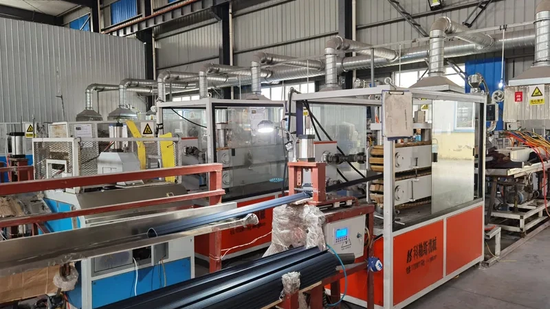
Every continuous plastic product that begins as melted polymer and leaves a shaped opening is an extrusion. That single principle covers an unusually wide family of parts: rigid window frames, pressure pipe, transparent tubes, sheet for fabrication, and multi-layer sections where a soft sealing lip is bonded onto a rigid core in one pass. Choosing the right type early matters because the die head, calibration method, cooling strategy and inspection plan all follow from it. This guide walks through the main types of plastic extrusions, the materials each favours, and the tolerances a buyer can reasonably hold in volume production.
- Plastic extrusion splits into several process families — profile extrusion, pipe and tube, sheet and film — plus co-extrusion variants of each, and every family has its own die, calibration and inspection logic.
- An extruded profile is defined by its cross-section; the extrusion die and downstream calibration determine whether that section holds dimension over a long run, not just on the first article.
- Co-extrusion combines up to three melt streams in one pass, so a rigid core, a soft sealing lip and a wear-resistant skin can come out of the line as a single part.
- Material and process type are coupled decisions: PVC dominates weatherable building profiles, TPE and TPV usually need a rigid carrier, and PC and PMMA serve transparent sections.
- Tolerances around ±0.05 mm are achievable on critical profile dimensions, but only where material, section geometry and measurement method are agreed before tooling is cut.
- Continuous-run sampling, not a single good first article, is the acceptance evidence that a process is stable.
What Are the Main Types of Plastic Extrusions?
The main types of plastic extrusions are profile extrusion, pipe and tube extrusion, sheet and film extrusion, and multi-layer co-extrusion applied to any of these. All of them share one principle — melted thermoplastic is forced through a shaped die head, calibrated, cooled and cut — but they differ in die design, calibration method and how the finished section is dimensioned and inspected.
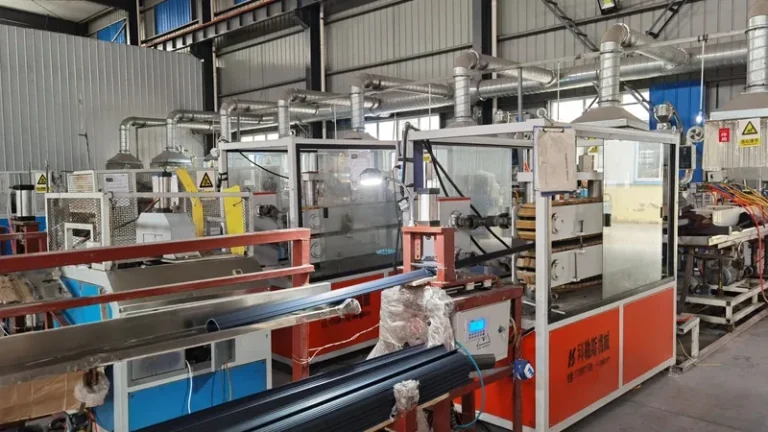
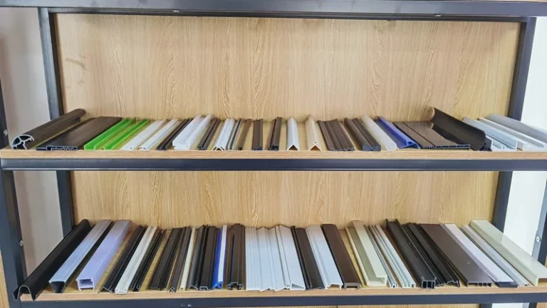
Profile extrusion is the broadest family. Here the product is a custom cross-section — a U-channel, a glazing gasket retainer, an edge trim, a structural rail — developed to a customer drawing rather than to a catalogue size. The section leaves the die head, passes through a vacuum calibration table that sets its outer geometry while the polymer is still soft, is pulled by a haul-off at a controlled draw ratio, and is cut or coiled to length. Non-standard sections are routinely developed this way, from a 5 mm sealing bead up to profiles 600 mm wide.
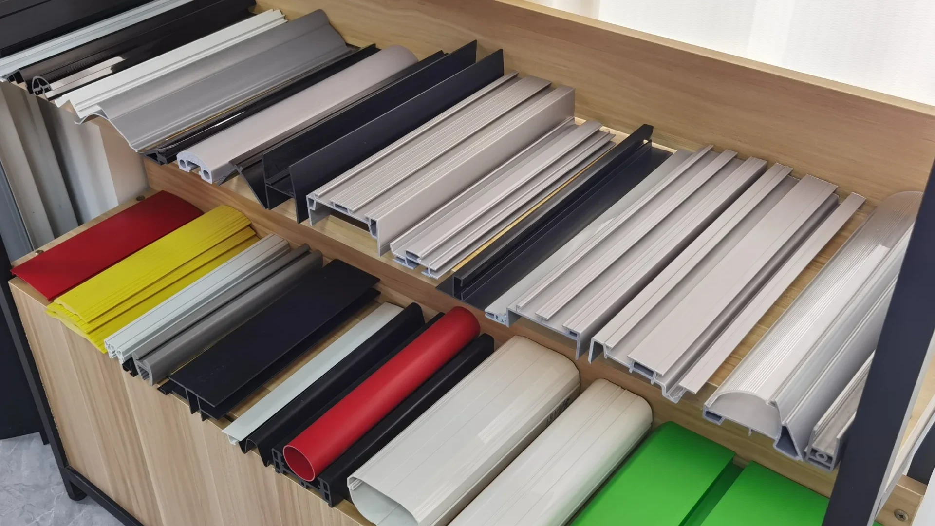
Pipe and tube extrusion runs the same physics with a different goal: a circular section controlled by outside diameter and wall thickness. Pressure pipe is dimensioned against SDR schedules and standards such as ASTM D2241 for PVC pressure pipe and ISO 4427 for polyethylene water pipe, while electronic and medical tubing is usually specified on tighter concentricity and inner-diameter limits than pressure ratings require.
Sheet extrusion produces flat stock from roughly 0.5 mm upward, which is then cut, routed or otherwise fabricated downstream. Film extrusion covers the thin end of the same spectrum. For a broader map of how these modes fit together, the plastic extrusion molding guide groups the process families by die type and output form.
Co-extrusion is less a separate type than a multiplier: it runs two or three melt streams through one die so that layers with different functions exit as a single section. It is treated in detail below.
Profile Extrusion: Custom Sections from an Extrusion Die
The extrusion die head is where most profile problems are won or lost. Melt entering the die must be distributed evenly across a section that is often asymmetric — one thick flange, one thin lip — and the flow channels inside the die are balanced to compensate. Designers also plan for draw-down: as the haul-off pulls the section out of the calibrator, it stretches slightly, so the die lands are cut larger than the final drawing. This is a mature engineering discipline, and independent bodies such as the SPE Extrusion Division publish technical resources on die design and process troubleshooting. Getting the flow balance right is why custom dies go through trial and correction before production.
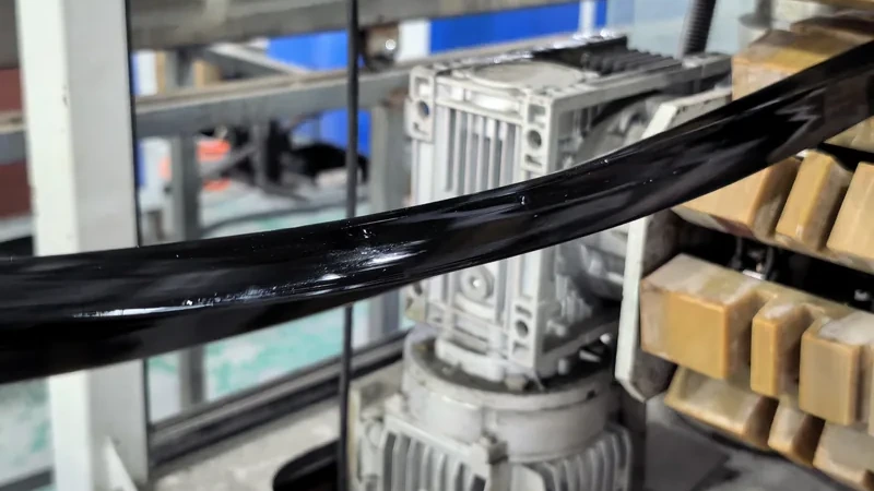
Calibration and cooling then lock the geometry in. A vacuum calibrator holds the soft section against cooled surfaces while water jackets remove heat; insufficient vacuum shows up as poor edge definition, while over-aggressive cooling can freeze in stresses that release as warp days later. For building products, geometry is not only cosmetic: EN 12608 specifies the profile geometry, impact resistance after ageing and heat reversion limits that PVC-U window and door profiles must meet1, which means calibrator design directly affects compliance.
Because sections are developed to customer drawings, the drawing review matters as much as the machine. Wall transitions should be gradual, internal voids must be buildable with the calibration system, and tolerances should be classified rather than applied globally. Prototyping, small batches and volume production all sit on the same line type, which is why a section proven at low volume scales without redesign. The full scope of what a supplier can carry — die development, in-line operations, batch sizes — is worth comparing against your project before tooling is committed, and ZetarVac’s service overview summarises that scope in one place.
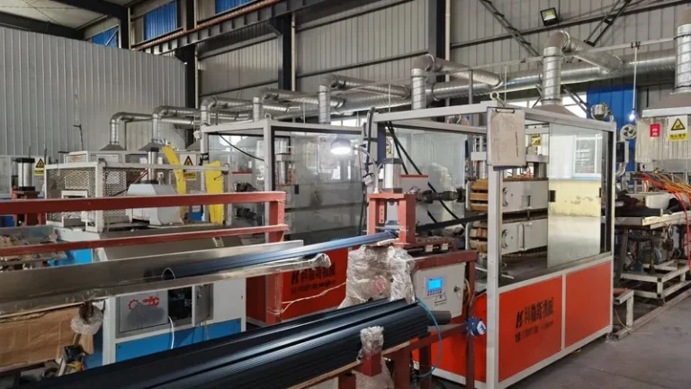
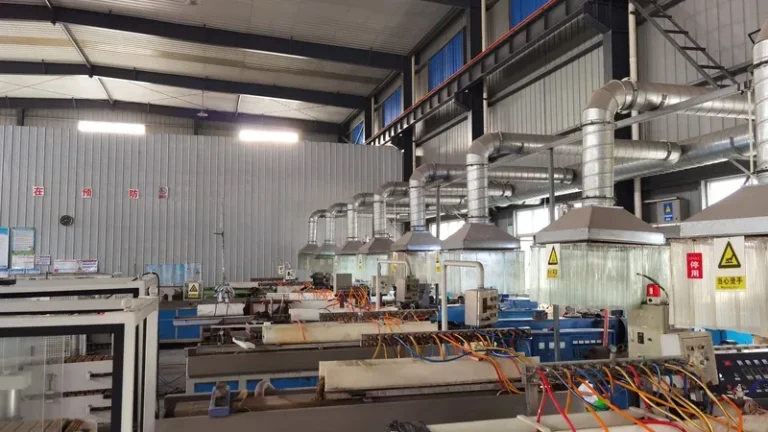
ZetarVac runs more than 7 automated extrusion lines with a maximum profile width of 600 mm, inside a plant with over 45 production lines in total. For a buyer, that means wide or multi-cavity sections are not forced onto tooling sized for narrow output, and larger programmes are not queued behind a single machine.
Before tooling is cut, one question deserves a straight answer from both sides: when is the process actually accepted for production?
"If the first article passes inspection, the profile extrusion process is ready for volume production."False
A first article is a single snapshot taken from a short, closely supervised run. It cannot reveal slow drift in melt temperature, calibration vacuum or haul-off wear that only appears over several hundred metres, so accepting it early leaves tolerance escapes to be discovered at incoming inspection.
"Production stability is proven by continuous-run sampling, not by one good article."True
Sampling dimensional checkpoints at defined intervals across a full run exposes drift that a single article hides. Agreeing run length, sample frequency and measurement method before mass production turns acceptance of the extruded profile into a repeatable, evidence-based decision.
How Does Co-Extrusion Change the Design Envelope?
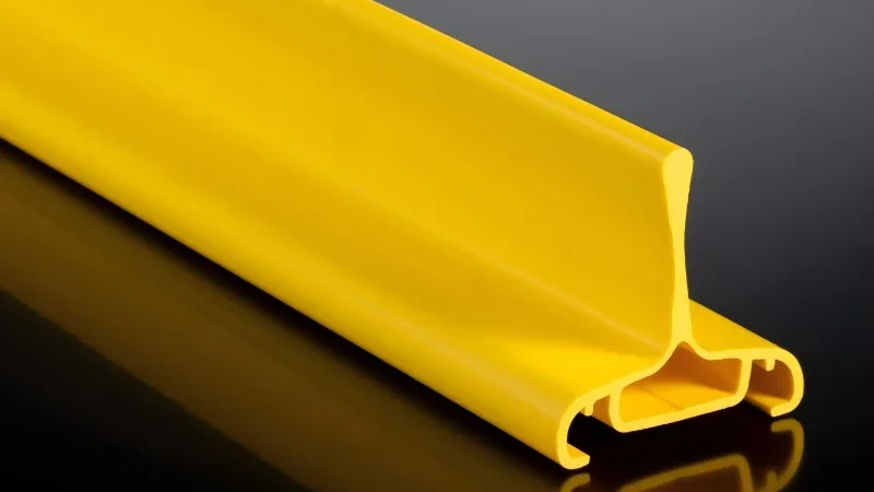
Co-extrusion runs two or three melt streams through a single die head, so one profile can combine materials with different functions — a rigid core with a soft sealing lip, or a tough skin over a cost-efficient core. Up to three layers in one pass is standard practice on modern lines2.
The practical value shows in real sections. An automotive seat slide rail strip is typically PP+TPV co-extrusion: the PP carries structural load while the TPV layer forms a flexible lip that seals out dust, guides the seat and keeps friction low over its service life. A robot vacuum squeegee strip uses ABS+TPU the same way — ABS provides the rigid support, TPU the wiping edge that must resist wear without scratching floors.
Other running combinations extend the logic: PVC+TPU pairs a low-cost body with an abrasion-resistant skin, TPV+CPVC puts an elastomeric surface over a heat- and chemical-resistant substrate, and PP+TPE covers softer touch profiles. Foam extrusion adds a foamed core inside a solid skin for stiffness at low weight. Each combination must work inside a melt-temperature window both materials can share, and interface adhesion between layers must be verified, not assumed.
The buyer-side checkpoints are concrete: specify layer thickness and how it will be measured, confirm the material combination has run in production before, and treat the layer interface as a named characteristic in the control plan rather than an incidental result of the die design. Automotive and industrial sections of this kind are exactly what ZetarVac’s plastic extrusion manufacturing operation runs daily, so a candidate combination can be checked against real production data before you commit to a die.
Co-extrusion on these lines reaches three layers in a single pass, with combinations actually running in production including PP+TPV, PP+TPE, PVC+TPU, ABS+TPU and TPV+CPVC. If your design needs a rigid core with a soft sealing lip, a wear-resistant skin or a chemically resistant barrier, that architecture is standard practice here, not a special project.
Pipe, Tube and Sheet: Continuous Sections with Their Own Rules
Pipe brings the most codified requirements in the industry. Outside diameter, wall thickness and ovality are measured continuously, often with laser gauging directly after the calibrator, and pressure classes tie dimensions to material performance. For cable protection and guiding, a transparent PVC electronic tube profile is a typical single-extrusion product: the wall is sized for insulation and flexibility rather than pressure, and clarity itself becomes a checkpoint for melt quality.
Electrical and electronic applications also carry flammability expectations. UL 94 classifies the flammability of plastic materials used for parts in devices and appliances, so compounds for tube and channel products in these markets are selected and certified against it rather than chosen on price alone.
Drainage channels sit between pipe and profile: a PVC drainage channel profile is a continuous open section used for drainage and water diversion in building and industrial systems, and its custom cross-section makes volume production straightforward once the die is proven. Sheet, by contrast, is judged mainly on thickness profile across the width and on flatness, because downstream fabrication amplifies both deviations.
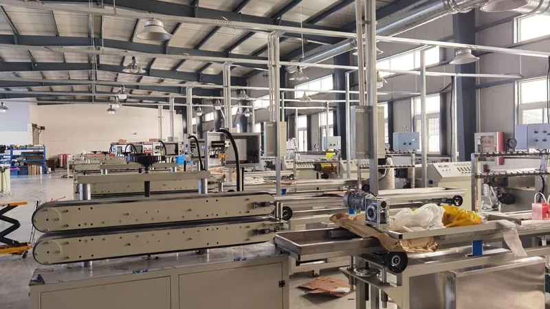
Across all of these families the haul-off deserves respect: it sets line speed and draw-down, and a slipping or worn belt shows up minutes later as a dimensional blip hundreds of metres down the line3.
Which Material Should You Specify for Each Extrusion Type?
Match the polymer to the function the section must perform: PVC for weatherable building profiles, ABS for finished industrial and automotive parts, HDPE and PP for chemical and wear resistance, PC and PMMA for transparent sections, TPE and TPV for flexible seals, and glass-filled compounds when stiffness governs the design.
Two properties deserve early attention. Heat resistance is best screened with the Vicat softening temperature, which ISO 306 defines as the temperature at which a flat specimen penetrates a set depth under a specified load4; it is a fast indicator of whether a profile will relax near a heat source. Mechanical properties of the chosen compound are verified by tensile testing, and for outdoor profiles the weathering behaviour is assessed under laboratory light exposure per ISO 4892 before a dark colour or a south-facing installation is committed.
| Material | Best-suited extrusion types | Why it is specified | Watch-outs |
|---|---|---|---|
| PVC | Window and door profiles, trims, pipes, sealing strips | Weatherability, cost efficiency, proven building-standard compliance | Narrow melt window demands stable process control |
| ABS | Automotive and industrial profiles, decorative parts | Impact strength and surface finish; co-extrudes with TPU | Limited UV resistance without a cap layer |
| HDPE | Pipes, edge trims, guide rails, wear strips | Chemical resistance and low-friction sliding | Higher shrinkage and thermal expansion |
| LDPE | Film, flexible tubing, soft profiles | Flexibility and sealing behaviour | Low stiffness limits structural use |
| PP | Profiles, pipes, functional parts | Fatigue and chemical resistance | Warpage risk on asymmetric sections |
| PC / PMMA | Transparent pipes, light covers, clear profiles | Optical clarity and light transmission | Requires drying discipline; PMMA is more brittle |
| PA6 / PA66 / POM | Precision profiles, guide rails, wear and mechanical parts | Stiffness and wear performance | Moisture uptake (PA) and tight melt control (POM) |
| TPE / TPV | Sealing strips, gaskets, automotive and building seals | Elastic recovery across temperature | Usually co-extruded onto a rigid carrier |
| PP/GF | High-strength industrial profiles | Stiffness-to-weight ratio | Die wear and surface appearance control |
Where a single material cannot satisfy two conflicting requirements — stiffness plus a soft sealing face, rigid support plus abrasion resistance — that is the signal to move from single-layer to a co-extruded profile architecture instead of compromising one property for the other.
What Tolerances Can a Profile Extrusion Actually Hold?
On a well-designed cross-section, a capable line can hold ±0.05 mm on critical profile dimensions, subject to material and section geometry. General, non-critical dimensions are normally held to wider, material-specific limits, and the drawing should state clearly which is which.
Variation has identifiable sources: melt temperature shifts change shrinkage and draw-down, haul-off speed fluctuation changes wall thickness, and thick-to-thin transitions in the section cool at different rates and pull the part out of straight. None of these can be inspected out at the end; they are controlled in the process, which is why calibration quality and line synchronisation matter more than end-of-line sampling alone.
Tensile properties of the compound are confirmed per ASTM D638, the standard tensile test method for plastics5, but dimensional acceptance is a separate discipline. In practice: agree measurement methods and gauges during drawing review, define critical dimensions against the mating part, and require process data across a continuous run rather than at isolated moments.
"Every dimension on an extruded profile can be held to ±0.05 mm."False
A blanket ±0.05 mm ignores how polymer shrinkage, wall thickness and section geometry drive variation. Applying it to non-critical features inflates cost and generates rejects the process was never able to control in the first place.
"Tight tolerances belong only on critical, function-bearing dimensions."True
Classifying cross-section features into critical and general bands lets the line concentrate melt and calibration control where the part actually functions. The result is a section that holds ±0.05 mm where it matters while remaining economical to produce in volume.
Secondary features created on the line should sit in the same control plan as the section dimensions, since they are produced in the same continuous process and inherit its stability.
Punching, embossing and printing run in-line on the extrusion lines, so holes, texture and marking are applied while the profile is still being produced. Removing these steps from separate secondary operations shortens the route a batch takes through the plant and removes a common source of handling scratches and mismatched hole patterns.
FAQ
How many types of plastic extrusion are there?
Most classifications recognise four families — profile, pipe and tube, sheet and film, plus specialty forms such as monofilament — with co-extrusion as a multi-layer variant applicable to each. In practice a buyer usually decides between a standard catalogue section, a custom profile to drawing, and a co-extruded architecture.
What is the difference between single-layer and co-extruded profiles?
A single-layer profile is one homogeneous compound throughout, which is simple to specify and economical when one material can do everything. A co-extruded profile bonds two or three compounds so each layer does its own job — structural support, sealing, wear resistance — and the design question becomes whether interface adhesion and layer thickness can be held in production.
What tolerance can an extruded profile realistically hold?
Critical dimensions on a favourable cross-section can be held to ±0.05 mm, subject to material and geometry. Blanket tolerances across every feature are neither realistic nor economical; the drawing should classify dimensions so the process concentrates control where the part functions.
Which material is best for outdoor extruded profiles?
PVC and ASA are the default choices for weatherable building profiles, because both resist UV and colour drift in outdoor exposure, and window-grade PVC is governed by EN 12608. For structural outdoor parts, capped or co-extruded constructions place the weatherable layer only where it is needed.
Can secondary operations be done in-line on an extrusion line?
Yes — punching, embossing and printing can all run in-line while the profile is produced, so holes, texture and marking arrive without a separate handling step. Confirm hole-pattern tolerances and print durability requirements during drawing review, because in-line operations are set up together with the tooling.
If you are evaluating which extrusion type fits a new section, share your drawings and talk to an engineer through ZetarVac’s custom plastic extrusion manufacturing page, or start from the service overview to review the full extrusion capability set first.
-
EN 12608: European standard for unplasticized PVC (PVC-U) window and door profiles, covering profile geometry, impact resistance after ageing and heat reversion. ↩
-
Co-extrusion: An extrusion process in which two or more melt streams are combined through a single die head to form a layered profile. ↩
-
Haul-off: The downstream unit that grips and continuously pulls the extruded section, setting line speed, draw-down and final dimensions. ↩
-
ISO 306: Standard for determining the Vicat softening temperature of thermoplastics, used as an indicator of heat and creep resistance. ↩
-
ASTM D638: Standard test method for the tensile properties of plastics, commonly cited for extruded compounds and profiles. ↩