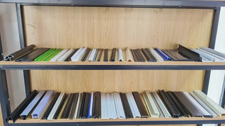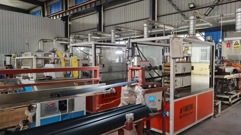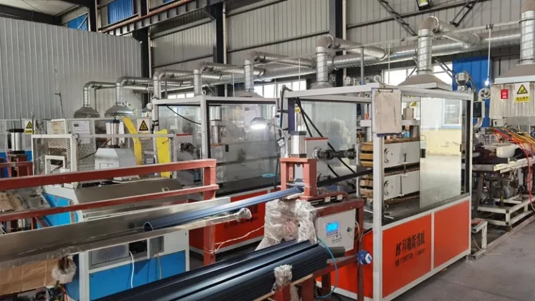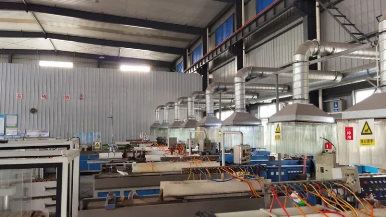
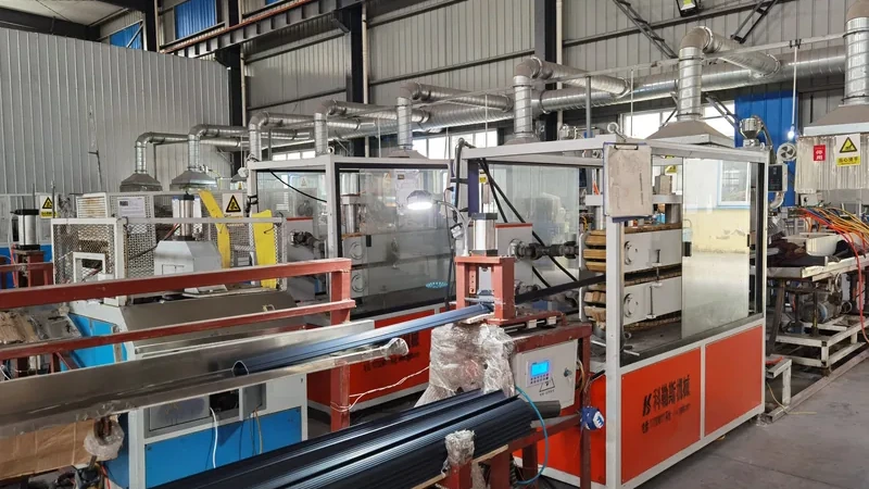
Draw down ratio rarely appears on a customer drawing, yet it decides whether an extruded profile lands on dimension or drifts toward the scrap bin. It sits at the junction of the extrusion die, the vacuum calibrator and the haul-off — one of the first numbers a die designer calculates, and one of the last things a buyer thinks to ask about. This guide explains what draw down ratio means, how it interacts with sizing and line speed, what goes wrong when it is set badly, and how to verify it from sampling through volume production. For wider process context, see the plastic extrusion molding overview.
- Draw down ratio (DDR) is the ratio of the die opening cross-sectional area to the finished product cross-sectional area — it states how many times the melt is stretched after leaving the die head.
- Conventional windows run from about 1.05–1.20 for rigid PVC to 3.0 for soft compounds, always depending on material grade, wall thickness and the specific line.
- Too much draw builds molecular orientation: post-extrusion shrinkage, warpage, thin walls and heat reversion. Too little draw gives dull surfaces, rounded edges and loose, unstable sizing.
- In co-extrusion every layer shares one overall draw, so layer ratios are set by individual layer throughput and die head design, not by the haul-off alone.
- First-article approval does not lock the setting; melt temperature drift, resin lots and haul-off wear all move the effective draw, so it needs periodic verification.
- Share profile drawings early so the die head and calibrator can be sized around a realistic draw window.
What Is Draw Down Ratio in Extrusion?
Draw down ratio is the ratio between the cross-sectional area of the extrusion die opening and the cross-sectional area of the finished profile. Because molten polymer leaves the die head larger than the delivered product, the haul-off stretches the extrudate down to size, and DDR states how many times that area reduction happens. A DDR of 1.2 means the die opening is roughly 20 percent larger in area than the finished section.1
In practice the calculation is simple in principle and demanding in detail. For a tube it follows directly from outside diameter and wall thickness on both the die and the product. For a complex custom profile it becomes an area comparison between the die land drawing and the final section, normally done in CAD. The common mistake is treating DDR as a diameter ratio; on tubing that alone skews the number badly, and on shaped profiles it hides the real draw entirely.
DDR is tightly coupled to die swell.2 As the melt exits the die, elastic recovery expands it beyond the die opening; draw-down then pulls it back. A correctly chosen draw down ratio accounts for both effects at once: the die is cut larger than the product to absorb swell, and the haul-off provides the stretch that seats the extrudate against the sizing tool. That is why die design and line settings are developed together, not sequentially.
How Draw Down Ratio Works on the Line
The downstream chain is easy to describe and unforgiving to tune. Melt leaves the die head at a controlled throughput. It passes through a short air gap or directly into a calibrator — a water-cooled sizing die that sets the outer contour while vacuum pulls the hot surface against its channels.3 The haul-off grips the profile with belts or tracks and pulls it at a constant, controlled speed.4 Every square millimeter of difference between the die opening and the finished product is absorbed by that stretch.
Line speed is the practical lever. With a fixed die and fixed extruder output, faster haul-off means more draw, a lighter section and thinner walls; slower haul-off means less draw and a heavier section. Dimension control on a profile line is therefore fundamentally a speed-matching problem: operators trim wall thickness by moving haul-off and throughput together, and the total draw tells you how much orientation is being stored in the part.
Material behavior sets the boundaries of that speed matching. Stiff, high-viscosity compounds tolerate only modest draw before surface stress, shrinkage or edge tearing appear. Soft, low-viscosity compounds can be drawn much harder, which is why flexible profiles are routinely produced at draw levels several times higher than rigid ones. Melt temperature shifts the balance too: a hotter melt stretches more easily, so the same die can behave differently across a modest temperature drift.
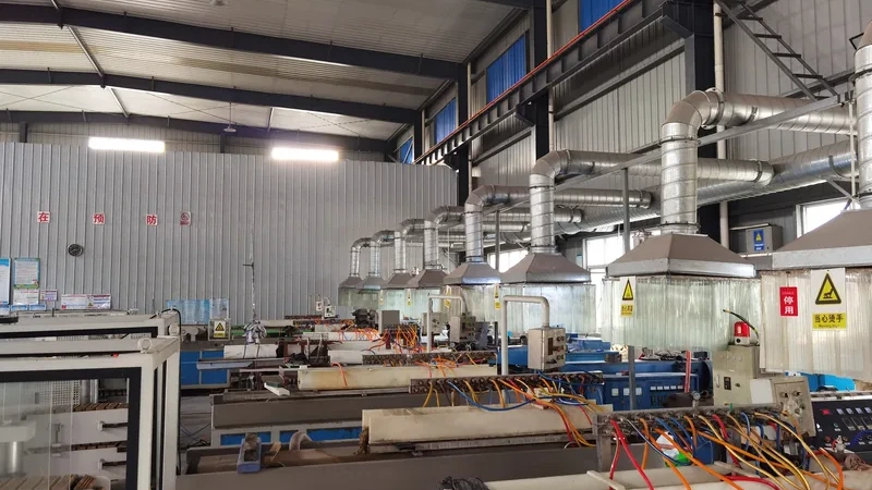
Standards make the effect of over-drawing visible rather than theoretical. EN 12608 specifies the profile geometry, impact resistance and heat reversion requirements for unplasticized PVC window and door profiles, and heat reversion is exactly the property that exposes how much draw-induced orientation a profile carries — pull it too hard and the section shrinks measurably when reheated.
Why Draw Down Ratio Matters for Tolerance and Surface
Dimensional stability is the first payoff of getting draw right. A profile drawn inside a sane window relaxes quickly in the calibrator and cooling bath, so its cross-section stays where it was set. Push the draw too far and stored orientation keeps relaxing after the line: lengths shrink, walls thin, and flat sections bow toward the stressed face hours or days after production. These are among the most common extrusion defects, and they are regularly misdiagnosed as cooling problems when the root cause is draw. The extrusion defect troubleshooting guide covers these symptoms in detail.
Surface quality follows the same logic. Inside the window, draw presses the melt evenly against the sizing channels and produces clean edges and consistent gloss. Outside it, the surface shows mattness, waviness or edge tearing as stretch stress concentrates, and no amount of vacuum tuning downstream recovers the definition.
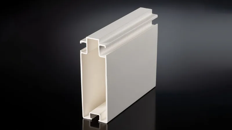
The table below gives engineering-conventional starting windows by material class. They are sanity checks for reviewing a die design or a supplier’s setup sheet, not universal specifications — the right window always depends on compound grade, section geometry and the line itself.
| Material class | Conventional DDR window | Why the window sits there |
|---|---|---|
| Rigid PVC (PVC-U) | 1.05–1.20 | High melt viscosity; excess draw drives heat reversion and impact loss |
| HDPE / PE | 1.10–1.30 | Moderate draw is tolerable; orientation affects shrinkage behavior |
| PP | 1.10–1.30 | Stiffer melt than PE; window narrows at lower melt temperature |
| Flexible PVC | 1.5–3.0 | Soft compounds stretch heavily to reach thin, flexible sections |
| TPE / TPU | 1.5–3.0+ | Elastic melts draw hard but recover; balance against surface quality |
"A bigger draw down ratio always improves surface finish, so the die should be cut as large as possible."False
The logic only holds inside a narrow window. Beyond it, stretch-induced orientation raises residual stress, and the surface responds with mattness, waviness or edge tearing instead of gloss. The consequence is a profile that passes first inspection but warps, shrinks or fails reversion checks later.
"Draw down ratio must stay inside a controlled window matched to the material, wall thickness and line speed."True
Inside its window, draw stabilizes the extrudate against the calibrator and yields a smooth, well-defined surface. Outside it, no downstream adjustment recovers the lost dimensional stability, which is why die designers calculate DDR before cutting steel rather than after.
Neither window is a marketing number. When a supplier commits to a tight cross-section tolerance, the draw window behind the die is part of how that number is held run after run, and it is entirely fair to ask how it was chosen for your material and geometry.
ZetarVac runs 7+ automated extrusion lines with a maximum profile width of 600 mm and holds a minimum dimensional tolerance of ±0.05 mm on the profile cross-section, subject to material and section geometry. Tolerance at that class on wide or multi-cavity sections depends on keeping die design, calibrator sizing and draw settings consistent from the first sample onward.
What Happens When the Draw Down Ratio Is Wrong?
Too much draw builds molecular orientation that keeps relaxing after production, producing shrinkage, warpage, thin walls and heat reversion. Too little draw leaves the profile loose in the calibrator, giving dull surfaces, rounded edges, poor contour definition and dimensions that wander. Both directions cost yield, and neither can be fixed downstream of the haul-off.
On the high side the failure chain is well understood. Over-drawn profiles become anisotropic — stronger along the draw direction, weaker across it — and they shrink unevenly when reheated or aged outdoors. A decorative trim that measured flat at the line arrives bowed at assembly, and impact resistance can drop in rigid PVC as orientation concentrates stress along flow lines.
On the low side the melt is never stretched firmly against the sizing channels. The outer surface cools loosely, so contour sharpness suffers: crisp edges come off rounded, shallow ribs lose definition, and small throughput changes show up directly as size variation because vacuum is only partly controlling the section.
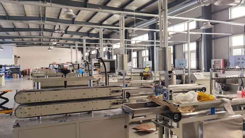
"Once the first article is approved, the draw settings are locked and will hold for the whole production run."False
First-article approval proves the setup worked at that moment, not that it is stable. Melt temperature drift, resin lots with different viscosity and haul-off belt wear all shift the effective draw during a run, so a profile that measured perfectly at sampling can be out of tolerance by mid-batch.
"Draw down ratio needs verification at sampling, after material or temperature changes, and at defined intervals during long runs."True
A cross-section check on cut samples costs minutes and catches drift before it becomes scrap. Tracking haul-off speed, melt temperature and weight per meter together gives an early warning while corrections are still small.
How Does Draw Down Ratio Behave in Co-Extrusion Profiles?
In a co-extruded profile every layer leaves the die head together and passes through one shared draw at the haul-off — there is no independent draw control per layer. What differs is how each material responds: a soft sealing lip and a rigid substrate stretched identically do not relax identically, so layer proportions have to be engineered at the die head, not corrected downstream.
Finished layer ratios are set by the combination of individual layer throughput and the shared overall draw. If the soft layer is fed generously and then stretched hard, it thins until it loses its sealing or wiping function; if the rigid substrate is underfed, the whole section sags because it carries the structural load. The die head therefore has to be sized so both materials sit inside their workable draw window at the same line speed. The multi-layer die head breakdown covers this design side.
"In a co-extruded profile, the haul-off speed can be tuned to bring each layer to its own specification independently."False
The haul-off applies one speed and one overall area reduction to the whole section, so no layer can be drawn independently. Layer proportions are fixed upstream by individual throughput and die head geometry; tuning one material at the haul-off distorts the others and the outer contour at the same time.
"Layer ratios in a co-extruded profile are set by individual layer throughput and die head design, then verified on cut cross-sections."True
Measuring layer thickness on cut samples confirms that both the rigid and the soft material sit inside their workable windows at production speed. It is the only reliable check, because layer behavior cannot be read from the outer surface of the profile alone.
This is why co-extrusion sampling records capture layer measurements alongside total draw, haul-off speed and melt temperature. When a re-run drifts, the record shows immediately whether the overall stretch changed or one layer lost proportion — two problems with two different fixes, one at the haul-off and one at the die head.
ZetarVac runs single, double and triple-layer co-extrusion in one pass — up to three layers — with combinations actually in production including PP+TPV, PP+TPE, PVC+TPU, ABS+TPU and TPV+CPVC. Multi-layer profiles only hold their layer ratios when the rigid and soft layers are both drawn inside their own workable window, which is why die head design and draw settings are developed together rather than sequentially.
How to Set and Verify Draw Down Ratio in Production
Setting starts on paper. Calculate the die opening area from the die drawing and the finished area from the product drawing, then confirm the ratio falls inside the conventional window for the material. If it does not, correct the die design before the trial — a die cut for the wrong draw window cannot be rescued by cooling water or vacuum.
During the trial, treat the line as a loop. Set initial throughput and haul-off speed from the calculated ratio, run until thermally stable, then cut and measure a full cross-section: widths, heights, wall thicknesses and layer ratios. Adjust in small steps — haul-off speed for fine wall corrections, throughput for overall size — and record every change against the resulting dimensions. Qualification samples conventionally come after roughly 30–60 minutes of stable running on most profile lines, once temperatures and draw have settled.
Verification goes beyond cold dimensions. Re-measure cut samples after a conditioning period to catch post-extrusion shrinkage, and for exterior rigid PVC sections use heat reversion5 to reveal stored orientation that a cold measurement misses. Tensile testing per ASTM D638 — the standard test method for tensile properties of plastics and the default tensile test cited for extruded profiles — shows whether draw orientation has raised strength along the profile while transverse properties fell.
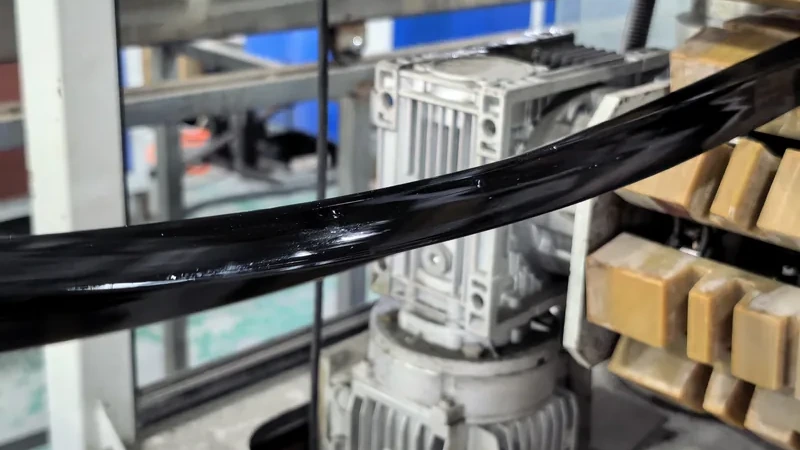
Keep the record alive afterward. DDR, haul-off speed, melt temperature and weight per meter belong in the setup sheet next to the dimension report, so any re-run starts from data rather than memory. For deeper processing background on die design and draw-down behavior, the SPE Extrusion Division maintains a public technical library for extrusion processors (SPE Extrusion Division).
ZetarVac supports prototyping, small batch and large batch production across its extrusion lines, with a reference monthly capacity of about 300–500 tonnes. The transition matters for draw settings: a profile qualified at sample volumes has to hold the same draw window at volume rates, so setup records and verification intervals should be written with that scale-up in mind.
FAQ
How is draw down ratio calculated for a custom profile?
Divide the cross-sectional area of the die opening by the cross-sectional area of the finished profile. For shaped sections this is done in CAD by comparing the die land drawing with the final part; it is an area ratio, not a diameter or weight ratio, and both values should be documented in the die design file.
What draw down ratio is typical for rigid PVC profiles?
Most rigid PVC profile extrusion runs in a conventional window of roughly 1.05–1.20. Higher values are possible for small or thin sections, but they increase orientation, so heat reversion and post-extrusion shrinkage have to be checked. The exact window depends on the compound, the section geometry and the line.
Does draw down ratio change mechanical properties?
Yes. Drawing orients the polymer molecules along the pull direction, which typically raises strength and stiffness along the profile and lowers them across it. In rigid materials excessive orientation also reduces impact resistance and increases heat reversion, which is why tensile and reversion testing belong in draw verification.
Why did my profile pass first article but warp weeks later?
That pattern usually points to stored draw orientation relaxing after production rather than to a tooling error. Check whether the DDR was pushed above the material’s conventional window, re-measure samples after conditioning, and compare haul-off speed and melt temperature records between the sampling run and production.
Who decides the draw down ratio — the buyer or the supplier?
The die designer sets it when sizing the extrusion die, but the buyer shapes it by sharing accurate section drawings, wall thicknesses, tolerances and end-use conditions early. Asking a supplier how they chose the draw window for your section is a fair and revealing technical question during supplier evaluation.
If you are evaluating suppliers for a custom profile, send your drawings and target tolerances and talk to an engineer about how the die and draw window will be set up for your section — you can review ZetarVac’s extrusion manufacturing capabilities or compare the full service scope before you do.
-
Draw down ratio (DDR): The ratio of the cross-sectional area of the extrusion die opening to the cross-sectional area of the finished extruded product; it expresses how many times the melt is stretched after leaving the die. ↩
-
Die swell: The elastic expansion of molten polymer as it exits the die, which makes the extrudate temporarily larger than the die opening before draw-down. ↩
-
Calibrator: A water-cooled sizing die, usually run under vacuum, that sets the outer contour of the hot extrudate immediately after it leaves the die. ↩
-
Haul-off: The belt or caterpillar unit that grips the extruded profile and pulls it through the sizing and cooling stages at a controlled, constant speed. ↩
-
Heat reversion: The tendency of an oriented plastic profile to shrink back toward its pre-stretched dimensions when reheated, used as a test to reveal stored draw orientation. ↩