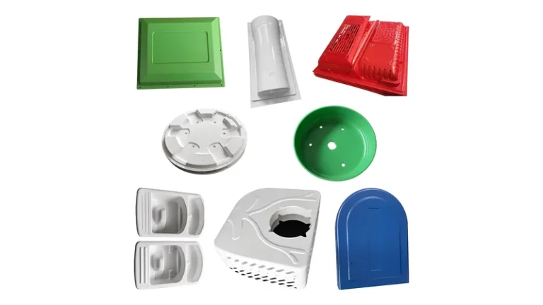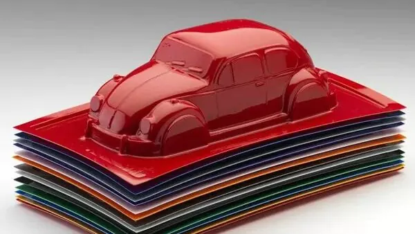
Plastic vacuum forming is the route engineers take when a design needs a large cover, tray, or housing and a high-pressure mould cannot justify its own cost. The process heats a thermoplastic sheet, stretches it over a mould, and uses vacuum to pull the sheet against the tool. This guide explains why the process earns its place in industrial manufacturing, where it delivers the most value, and which design rules keep a formed part out of trouble.
- Vacuum forming converts heated thermoplastic sheet into large parts with a single mould, so tooling cost and lead time stay far below cavity-filling processes.
- It is the economic choice for covers, housings, trays, and panels with any dimension above roughly 300 mm, from prototyping through mass production.
- Sheet gauge defines the starting wall: the process handles sheet from 0.5 to 15 mm and parts up to about 2,500 mm long.
- Material selection drives everything — ABS and PC/ABS for housings, HDPE and PP for trays, PC and PMMA for clear or protective covers.
- Formed-surface and trimmed-edge tolerances must be specified separately, because only CNC-trimmed features follow controlled tooling.
- Verified properties such as tensile strength and heat deflection come from standards like ISO 527-2 and ISO 75-2, not from datasheet estimates.
Why Is Plastic Vacuum Forming Used for Large Plastic Parts?
Vacuum forming is used because it converts a flat thermoplastic sheet into a three-dimensional part with a single low-pressure mould and modest clamping force. For covers, housings, trays, and panels with any dimension above roughly 300 mm, it beats alternative routes on tooling cost and lead time, while wall thickness stays adjustable simply by changing sheet gauge.
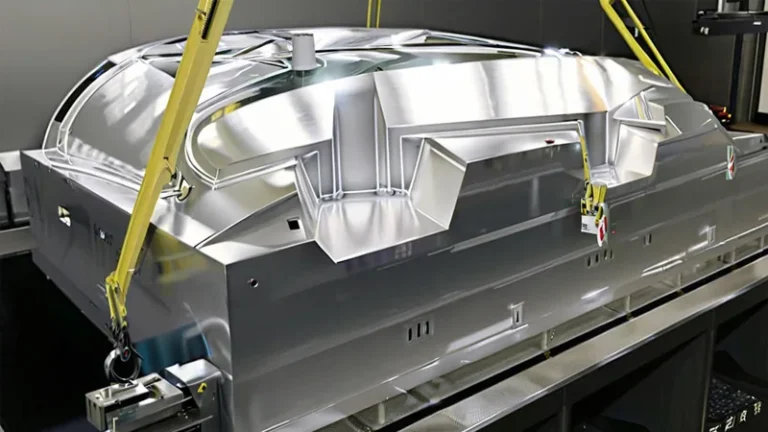
The economics follow from the tooling. A thermoforming mould is a machined or cast aluminium tool that sees almost no pressure — atmospheric pressure does the forming work. Because the tool is inexpensive to make and quick to modify, design iterations cost days rather than months. That matters most early in a programme, when a housing or tray still needs two or three correction loops before the design freezes.
Wall thickness is the second reason. In cavity-filling processes the wall is fixed by the tool; in thermoforming the wall starts as the sheet gauge and thins only where the sheet stretches. The same geometry can be trialled in 3 mm and 6 mm sheet to compare stiffness, weight, and cost without touching the tool. Sheet from 0.5 to 15 mm spans thin packaging inserts through heavy structural covers.
Part size seals the argument. Forming area scales cheaply: a bigger mould on a bigger machine, not a proportionally bigger tool bill. Parts up to about 2,500 mm long — full-length machine covers, equipment enclosures, large logistics trays — are routine work for heavy-gauge vacuum forming.
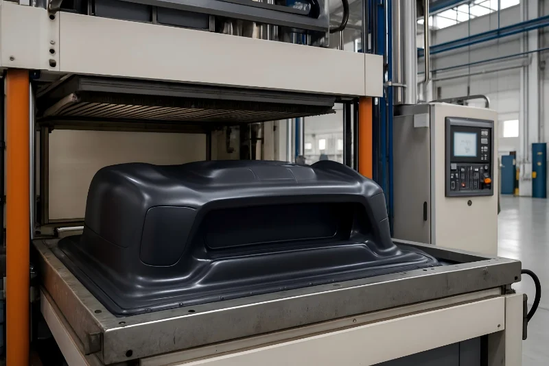
"Vacuum forming can hold machined-part tolerances across the whole part."False
Only the CNC-trimmed outline follows controlled tooling. The formed surface inherits the sheet, and wall thickness shifts with draw depth, so a blanket tight tolerance produces rejected parts and supplier disputes.
"Formed-surface and trimmed-edge tolerances must be specified separately."True
The tool side of a formed part tracks the mould accurately, while the free side and the wall thickness follow the stretched sheet. Assigning tighter limits only to CNC-trimmed features keeps drawings inspectable and production stable.
How the Heavy-Gauge Thermoforming Process Works
Heavy-gauge thermoforming runs as six disciplined steps, and each one has a failure mode when rushed.
Sheet selection: the engineer fixes resin, gauge, and texture first, because the sheet is the finished wall. Incoming sheet thickness tolerance becomes the baseline wall tolerance of the part, so a drawing written around a 6 mm nominal sheet should accept commercial sheet tolerance rather than invent a tighter one.
Heating: radiant heaters bring the sheet into its forming window, where the material sags under its own weight without melting. Thick sheet needs heat from both sides and several times the heating time of thin gauge. Rushing this stage is the most common cause of bubbles, poor detail, and cold-flow marks on the free surface.
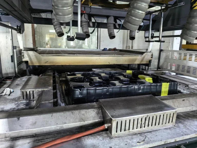
Pre-stretch and forming: a pre-bubble or plug assist controls where the sheet thins, then vacuum pulls it against the mould through ports sized for the required detail. Deep draws can fold excess sheet between features — a defect called webbing1 — which slower vacuum, better port placement, or wider feature spacing resolves.
Cooling: fans and water-cooled tool surfaces lock the shape in place. Uneven cooling warps large panels, so flatness-critical parts need symmetric airflow and a controlled release temperature instead of a fixed dwell time.
Trimming: a 5-axis CNC trimming centre cuts the outline, cut-outs, and mounting holes against the forming tool datum. Trimming in one setup keeps hole-to-edge relationships consistent from the first article to the last piece of the batch.
Verification: wall thickness is mapped with an ultrasonic gauge at corners and draw walls, where thinning concentrates. For structural parts, specimens cut from formed sheet are tested per ISO 527-2, which is the standard tensile test run on thermoformed sheet to confirm the forming cycle has not degraded strength or elongation.
ZetarVac runs more than 20 vacuum forming machines, processes sheet from 0.5 to 15 mm, forms parts up to about 2,500 mm long, and trims formed parts on a 5-axis CNC centre. For a buyer, that combination means one formed shell can replace an assembly of fabricated panels, with cut-outs and mounting holes following the forming tool.
What Materials Work Best in Vacuum Forming?
Thermoplastics with a wide, stable forming window work best. ABS, HDPE, PP, PVC, PC, and PMMA lead the list, and the right choice follows the load case, service temperature, clarity, and any flammability or hygiene requirement the part must satisfy.
| Material | Typical formed parts | Why it suits vacuum forming |
|---|---|---|
| ABS | Equipment housings, cases, guards | Wide forming window, clean trimming, good impact strength |
| HDPE | Industrial trays, equipment liners | Tough, chemical resistant, tolerant of deep draws |
| PP | Automotive interiors, trays, boxes | Fatigue and chemical resistance at moderate cost |
| PVC | Trays, packaging, industrial liners | Sharp detail definition, cost effective at volume |
| PC | Clear guards, protection covers | High impact strength with useful clarity |
| PMMA | Clear covers, displays, luminaires | Optical clarity and outdoor weathering stability |
| PC/ABS | Automotive interiors, housings | Heat resistance balanced with impact toughness |
| TPE | Soft liners, seals | Flexible sealing surfaces formed directly into the part |
Housings usually start with ABS or PC/ABS: both form evenly, trim cleanly, and accept texture and paint. Logistics and industrial trays lean on HDPE and PP for chemical resistance and impact toughness at low cost. PVC remains strong for packaging trays where detail definition matters, while clear parts divide between PC for impact performance and PMMA for optical quality.
For parts that live near motors, lamps, or washdown heat, check the heat deflection temperature measured under load per ISO 75-22 rather than trusting a datasheet value taken at a different stress level. A housing that stands straight on the bench can sag over a lamp bracket if its HDT margin is too thin.
The plant material library covers PVC, ABS, HDPE, LDPE, PP, PC, PMMA, PA6, PA66, POM, TPE, TPU, TPV, PC/ABS, ASA, and glass-filled PP, with reference monthly capacity of about 100,000 to 200,000 pieces. A housing and its matching soft liner or seal can therefore come from one supplier under one forming philosophy.
For a material-by-material breakdown, see which materials can be used in plastic vacuum forming.
"Thicker sheet always makes a stronger formed part."False
Bending stiffness scales with wall thickness cubed, so the claim only holds where the wall stays thick. Deep draws thin corners, and heavier gauge also needs longer heating and cooling, which raises warpage risk on large panels.
"Local thinning at corners matters more than nominal sheet gauge."True
Twenty percent thinning removes nearly half the local bending stiffness, because stiffness follows the third power of wall thickness. Place ribs, flanges, and fixing points where the draw keeps material thick.
Where Does Vacuum Forming Deliver the Most Value?
The process pays off wherever a large plastic part must look finished, carry modest structural loads, and stay affordable in mid volumes. Machine enclosures, logistics trays, agricultural equipment parts, and medical device housings are the classic applications.
Equipment enclosures show the process at its strongest, and two standards frame the design conversation for an electrical or medical housing. UL 943 classifies the flammability of plastic materials, and many equipment enclosures must meet a defined UL 94 rating before they can be built into electrical equipment. IEC 605294 defines the degrees of protection an enclosure provides against dust and water, which drives the flange, gasket groove, and fixing pattern of an IP-rated formed cover.
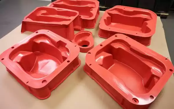
Trays exploit the same tooling economics at volume: one mould, one gauge of HDPE or PVC, and thousands of parts per month with repeatable cell geometry, stackable walls, and easy washing between cycles.
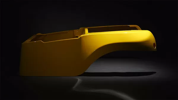
Three representative programmes show the range. An ABS seedling tray for agricultural use is formed as a multi-cavity tray with custom cell geometry and tray size matched to the nursery line. A PC housing for medical and diagnostic equipment becomes a large, complex curved shell with custom cut-outs, mounting holes, and reinforcement formed directly into the wall. A PMMA display cover for retail delivers high clarity with curved geometry that no flat-fabricated cover can match.

Which Design Rules Keep a Formed Part Manufacturable?
Respect the draw ratio, use generous radii, add draft to vertical walls, and place critical features where the sheet stays thick. These four rules prevent most of the scrap generated on a first formed part.
Draw ratio5 compares formed depth with the smallest mould opening at that depth. As a working guide, heavy-gauge parts stay comfortable near a 1:1 ratio; deeper geometry needs plug assist, sheet pre-stretch, or pressure forming to keep wall thickness acceptable. A review that computes the draw ratio before quoting avoids the classic surprise of corners thinned to less than half the nominal gauge.
Specify internal radii at two to three times sheet thickness where the design allows, and give tool-side walls 2–5° of draft so the part releases without drag marks. Radii tighter than the sheet thickness force the material to bridge, which is exactly where thinning and tearing start.
Mounting holes and cut-outs are CNC-trimmed after forming, never pre-cut into the sheet, because holes would leak vacuum and break the forming seal. Ribs and fixing bosses belong on thick regions, not at maximum draw depth, since webbing and thinning concentrate exactly there.
Remember which side is which: the mould side carries the tool texture and the best surface finish, while the free side shows any overheating. Surface texture decisions belong at tool design, not after first articles, because retexturing a tool costs far more than choosing it correctly the first time.

FAQ
What sheet thickness can heavy-gauge thermoforming handle?
The process works sheet from 0.5 to 15 mm. Thin gauges suit packaging inserts and covers, while heavy gauges above 6 mm suit structural trays, machine housings, and panels that carry fixing loads.
How large can a vacuum formed part be?
The maximum forming length is about 2,500 mm. Above roughly two metres, transport and trimming envelope become the limiting factors, so raise logistics early in the design review.
Is vacuum forming economical for low volumes?
Yes. Prototyping, small batches, and large batches are all supported, because the mould is inexpensive relative to cavity tooling. When a programme scales, reference monthly capacity reaches about 100,000 to 200,000 pieces.
Which standards apply to formed enclosures and covers?
UL 94 governs flammability, IEC 60529 defines degrees of protection against dust and water, and NEMA 250 covers enclosure types such as Type 4 and Type 4X for washdown environments. Material certificates and finished-part tests should map to the rating your equipment standard demands.
How are formed parts trimmed and finished?
On a 5-axis CNC trimming centre, which cuts the outline, cut-outs, and holes against the forming tool datum. That keeps trimmed features consistent from the first article through the final piece of the batch.
To keep exploring how heavy-gauge vacuum forming could fit your next housing or tray programme, walk through the vacuum forming process guide or see how a China vacuum forming manufacturer organises tooling, materials, and trimming end to end.
-
Webbing: webbing refers to thin folds of stretched sheet that bridge between features during deep draws, caused by excess material or unbalanced vacuum. ↩
-
HDT: HDT refers to heat deflection temperature, the temperature at which a bar deflects a set amount under a defined flexural load per ISO 75-2. ↩
-
UL 94: UL 94 refers to the flammability classification standard for plastic materials, with ratings such as V-0 and HB. ↩
-
IP code: IP code refers to the IEC 60529 classification of enclosure protection against dust and water ingress, written as IPXY. ↩
-
Draw ratio: draw ratio refers to formed part depth divided by the smallest mould opening at that depth, a measure of forming severity. ↩