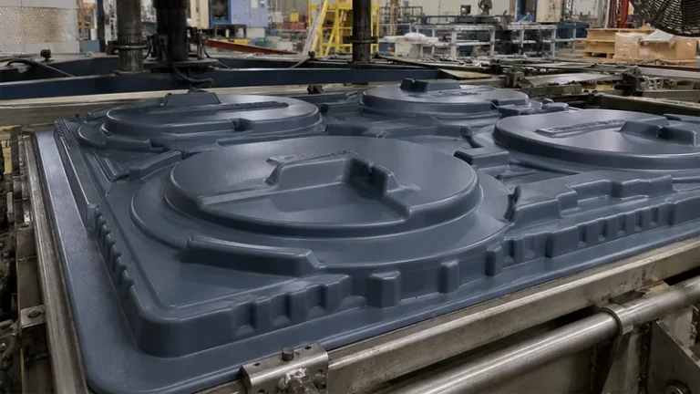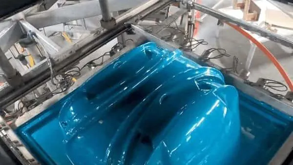
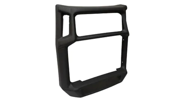
Deep draw thermoforming promises large, complex parts from a single sheet of plastic — until the corners tear or the walls come out paper thin. Tearing and thin-out are the two defects that decide whether a deep draw part is manufacturable at all, and both trace back to a short list of process variables that you can control. This guide explains why material piles up in some regions and vanishes in others, and what to change on the heater, on the tool, and in the inspection plan.
- Tearing and thin-out are driven by draw ratio, sheet temperature uniformity, and how the sheet is pre-stretched before vacuum pulls it down.
- Treat any local wall below roughly half of the starting sheet gauge as a design risk, and verify with a full thickness map rather than one caliper reading.
- Plug assist and billow pre-stretch move material toward the bottom corners before full vacuum is applied.
- Corner radii, draft angle, and plug temperature influence wall distribution as much as resin selection does.
- First-article approval for deep draw parts should include tensile data to ISO 527-2 and a heat deflection check.
Why Deep Draws Tear and Thin Out
In vacuum forming, the sheet does all the work of reaching the mold. Once the clamped, heated plastic is pulled down by vacuum, every square centimeter of the formed surface has to come from somewhere. Deep draw geometry makes that arithmetic brutal: the vertical walls and bottom corners demand material from a sheet that is already locked at the clamp frame, so the regions that touch the tool last — usually the lower corners — end up stretched far beyond their neighbors.
Thin-out follows a predictable pattern. Areas that contact the mold first freeze at nearly full gauge, while material that travels the longest path — over the rim, down the wall, into the corner — arrives thinnest. When the local draw exceeds what the polymer can carry at forming temperature, the wall tears instead of simply thinning. Tear location is diagnostic: a split mid-wall points at sheet temperature or vacuum timing, while a clean tear in a bottom corner usually points at draw ratio1 or corner geometry.
Draw ratio is the first number to calculate, before any tooling money is spent. It compares the formed surface area to the flat sheet area available over the mold opening, and it sets the practical depth ceiling for a given material and gauge; the full method is covered in our draw ratio calculation guide for thick-wall thermoforming. If a customer drawing shows deep rectangular pockets, this is where the review starts.
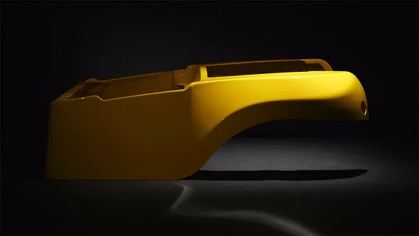
Heating comes next in the failure chain. Uneven sheet heating guarantees uneven wall distribution no matter how good the tool is, because cooler zones stretch less and dump their strain into the hotter zones. Industrial practice keeps the sheet within a narrow, uniform window around the material’s forming temperature using zone-controlled top and bottom heater banks — not by chasing maximum softness. A common working target is holding the sheet-to-sheet temperature spread to a low double-digit number of degrees Celsius, though the exact window depends on resin and machine.
Deep draws also sit at the demanding end of the process range. The distinction between heavy and thin gauge work changes heating strategy, forming method, and failure modes, and it is worth a separate read if your parts span both regimes. For the broader process picture, our vacuum forming guide covers the fundamentals; the rest of this article stays on deep draw defects.
Webbing and tearing are cousins. When excess sheet material has nowhere to go between tall features, it folds into webs, and the same excess tension that causes webbing can pull a wall past its elongation limit on the opposite side. Both defects respond to the same levers: feature spacing, plug design, and vacuum ramp.
How Thin Can a Deep Draw Go Before It Fails?
There is no universal limit, because the answer depends on resin, gauge, and load, but a practical screening rule for heavy gauge parts is to treat any local wall below roughly half of the starting sheet gauge as a design risk. Below that point stiffness falls faster than thickness, corners that felt solid in CAD fail in service, and only a thickness map — not a single spot check — reveals the true minimum.
The reason a fifty percent wall is more serious than it sounds is bending stiffness: flexural stiffness scales with roughly the cube of thickness, so a corner formed down from 5 mm to 2.5 mm carries around one eighth of the original panel stiffness. ASTM D790, the standard test for flexural properties of plastics, is the usual way to confirm that a thinned panel still meets its stiffness requirement. For equipment covers and structural panels, that single check separates parts that pass handling from parts that drum, flex, or crack at the mounting bosses.
Wall thinning also shrinks the thermal margin. A thinned section reaches its heat deflection temperature2 sooner than a full-gauge wall, which matters for housings that sit near motors, drives, or outdoor solar load. Distribution and material limits therefore have to be judged together, not one at a time.
"Heating the sheet hotter always fixes thin-out, because softer plastic stretches further."False
A hotter sheet does stretch more, but it also sags, sticks to the plug, and loses melt strength, so the tear moves instead of disappearing. Overheating is one of the most common causes of webbing in deep draws. The fix is a narrower and more uniform temperature window, not a higher one.
"Uniform sheet temperature across the whole sheet is the foundation of even wall distribution."True
Correct. When the sheet enters the forming station within a tight temperature window, strain spreads evenly instead of concentrating in hot zones. Combined with a staged vacuum ramp, uniform heating is the single most effective lever against both tearing and thin-out.
These screening rules also assume the incoming sheet is consistent. A new resin lot or gauge batch moves the entire thickness map up or down, which is why the inspection plan below ties first-article approval to the sheet data, not just to the tool.
Our heavy gauge thermoforming line processes sheet from 0.5 to 15 mm with a maximum forming length of about 2,500 mm, so deep draws are trialed at the production gauge and size rather than scaled down. That matters because thin-out behaviour does not scale linearly between gauges or part sizes.
What Role Does Plug Assist Play in Deep Draw Thermoforming?
A plug assist3 is a shaped, typically heated helper that mechanically pre-stretches the hot sheet toward the cavity before full vacuum is applied. By carrying material partway down the draw, it stops the sheet from sealing against the mold rim early and pushes more polymer into the bottom corners where thin-out is worst.
For deep rectangular housings, plug geometry decides most of the wall distribution. Plug faces are commonly built from wood, syntactic foam, or felt-covered aluminum and run cooler than the sheet so they do not mark the surface; penetration depth and speed set how much material is parked in the corners before vacuum finishes the form. A shallow plug leaves the corners to the vacuum, which thins them; a plug that runs too deep or too hot chills or marks the sheet and prints its texture onto the part.
Billow pre-stretch is the companion technique. Blowing a controlled bubble upward before the plug descends puts the sheet under even tension and pre-thins it uniformly, which is why billow plus plug is the standard combination for deep draws. Practice limits bubble height to a fraction of the draw depth and watches for instability, which shows up as ring-shaped thin zones and, at the extreme, a bursting bubble that scraps the sheet.
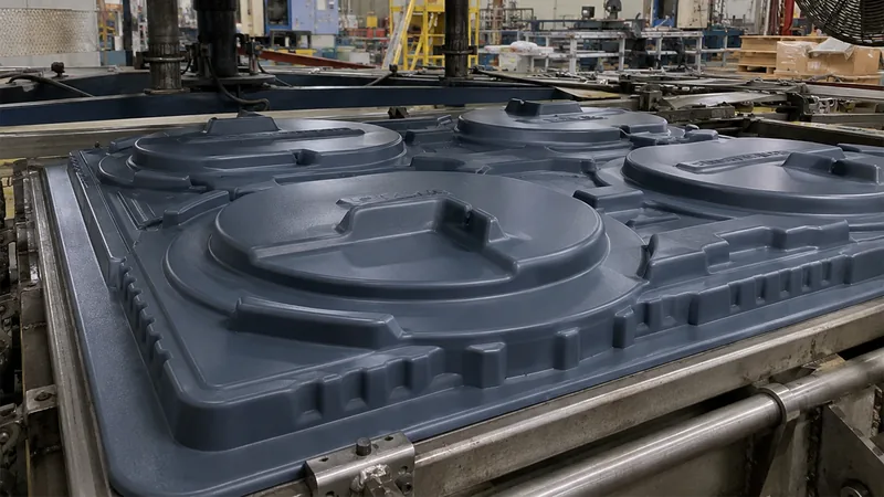
The mold itself is the last mechanical lever. Generous corner radii — commonly at least half the sheet thickness, and more on deep draws — spread strain instead of concentrating it, and adequate draft angle keeps the formed part from gripping the tool during cooling, which would otherwise drag and thin the walls on ejection. Mold temperature matters too: a cold tool freezes the surface where it touches first, locking thickness differences in place.
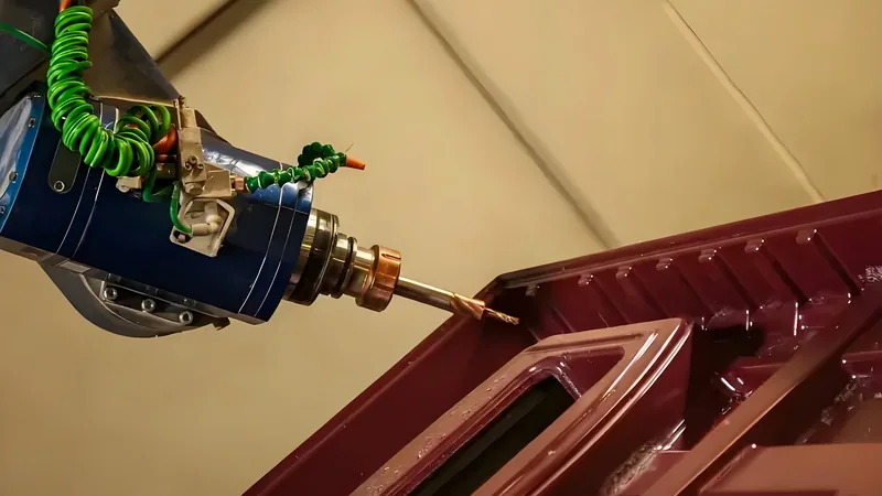
Which Materials Stretch Further in Deep Draws?
ABS, PC, and PP are the usual candidates for deep draws because they combine high elongation at forming temperature with stable melt strength. Rigid and filled grades trade some of that drawability for stiffness or heat performance, which is a legitimate exchange when the part is a structural panel rather than a deep cover.
| Material | Deep draw behaviour | Typical formed applications |
|---|---|---|
| ABS | Forgiving forming window, good stretch; watch chill marks from a cold plug | Equipment housings, cases, guards |
| PC | High hot strength and impact resistance; needs careful heating control | Clear guards, equipment protection covers, automotive parts |
| PP | Excellent elongation, but sags heavily if overheated | Automotive interior parts, trays, packaging, boxes |
| HDPE | Very forgiving window; lower stiffness limits how thin walls can go | Industrial trays, equipment liners, storage boxes |
| PVC | Balanced drawability and cost; keep temperature below the degradation range | Trays, packaging, industrial enclosures, liners |
| PP/GF | Glass fill restricts stretch; suited to moderate draws needing stiffness | Automotive and industrial structural parts |
"Starting with thicker sheet automatically prevents thin-out in deep draws."False
Thicker stock raises the final minimum wall in absolute millimetres, but it does not change the distribution: the same corners still finish at roughly the same percentage of gauge. You pay for heavier sheet, longer heating, and longer cycles while the corner remains the weak point. Geometry and pre-stretch fix distribution; gauge only shifts the numbers.
"Draw ratio, not starting gauge, is the first number to check on a deep draw part."True
Correct. The draw ratio tells you whether the geometry is formable in the chosen material before any tooling is cut. If the ratio sits beyond the material’s comfortable range, no gauge increase rescues the corners; the part needs revised radii, a plug assist, or a different forming approach.
Material choice then interacts with the geometry fixes above. A deep draw that is marginal in a filled grade may be comfortable in ABS at the same gauge, and a clear PC cover behaves differently from an opaque PP tray at an identical draw ratio, which is why material selection is revisited after the draw ratio review rather than before it.
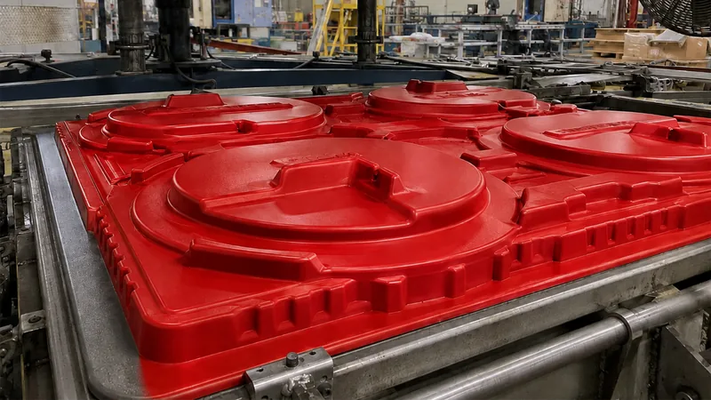
One of our reference parts is a PC vacuum-formed medical equipment housing: a large, complex curved cover with custom cut-outs, mounting holes and reinforcement. Curved deep geometry of that type is exactly where thickness mapping on first articles earns its keep, because the thin spot is rarely where intuition puts it.
How Do You Catch Thinning Before It Reaches Production?
Map wall thickness on the first article instead of spot-checking it. An ultrasonic gauge swept across corners, walls, and flange edges produces a thickness map in minutes, and that map — with the minimum wall located and recorded — is the acceptance document for the process, not the single measurement that happens to land on the flange.
Two standards belong in the first-article plan. ISO 527-2 is the standard tensile test for plastics and defines how tensile properties of thermoforming sheet are measured, so a new lot can be compared against the lot the process was validated with on identical terms. ISO 75-2 defines the heat deflection temperature of plastics under load, the number that tells you whether a thinned panel holds its shape near operating temperature. Where the housing protects live electrical equipment, UL 944 flammability classification of the material is typically part of the enclosure specification.
Industry resources help here too: groups such as the SPE Thermoforming Division publish process and troubleshooting guidance for exactly this class of forming defects, and it is a sensible supplement to your own trial data.
"Once the first article passes, the deep draw process is stable for production."False
A first article only proves that the tool, the sheet lot, and the setup worked together on that day. Heater ageing, ambient temperature shifts, and new sheet lots all move the wall distribution afterwards. Stability comes from controlling those inputs and re-checking after changes, not from one approved part.
"Thickness mapping should be repeated whenever the sheet lot, heater settings, or plug change."True
Correct. Those three inputs govern wall distribution more than anything else on the machine. Re-mapping after any of them changes catches drift while it is still a setting adjustment, before it becomes a scraped batch or a field failure.
The same trial discipline applies when a deep draw moves between machines or between suppliers, because heater banks and plug tooling never behave identically from one cell to the next.
Prototyping, small batch and large batch production are all supported across 20+ vacuum forming machines, so plug and heating trials for a deep draw run at production conditions before volume commitment — the process you approve is the process that ships.
FAQ
Why does my part tear at the corners but not in the middle?
The corner is the last region to contact the mold, so it stretches the most, and a tear there usually means the local draw exceeds what the material and pre-stretch can deliver. Check plug penetration depth and bubble height before blaming the resin.
Can vacuum forming handle a draw ratio above 1.5?
It depends on resin and geometry. Many materials handle around 1.5 with a well-designed plug, but draws pushing toward 2 generally need billow pre-stretch, generous corner radii, and sometimes a redesigned part. Calculate it before tooling.
Does a faster vacuum pull reduce thinning or make it worse?
Usually worse. An abrupt vacuum pulse freezes the sheet wherever it lands first, so corners thin out more. A staged, ramped vacuum gives the sheet time to distribute strain before it touches down.
What sheet thickness should I start with for a deep draw?
Back-calculate from the minimum acceptable final wall. Estimate how severely your geometry thins the corners — deep draws commonly leave the corners well below the starting gauge — then choose a starting sheet thick enough that the predicted minimum wall clears your design requirement with margin. Confirm the estimate with a trial thickness map on the first article before committing to tooling or volume.
How long does it take to fix thin-out on an existing tool?
Heating and vacuum timing corrections are usually same-day machine trials. A plug geometry change means a new or modified plug, typically days rather than weeks. Changing mold corner radii is slowest because it touches the tool itself.
If you are comparing suppliers for a deep draw enclosure, tray, or housing, share your drawings with ZetarVac and we will review draw ratio, wall distribution risk, and material options with your team. Start on our China vacuum forming manufacturer page to talk to an engineer, or review our service scope to see where heavy gauge thermoformed parts fit in your project.
-
Draw ratio: The ratio of the formed part surface area to the flat sheet area available over the mold opening; it estimates how far the sheet must stretch. ↩
-
Heat deflection temperature (HDT): The temperature at which a plastic specimen deflects a defined amount under a specified flexural load, defined in ISO 75-2. ↩
-
Plug assist: A shaped helper plug that mechanically pre-stretches the hot sheet into the cavity before full vacuum is applied. ↩
-
UL 94: The flammability classification standard for plastic materials, commonly required for electrical equipment enclosures. ↩