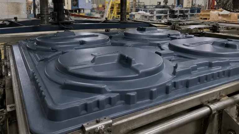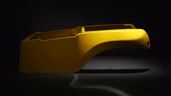
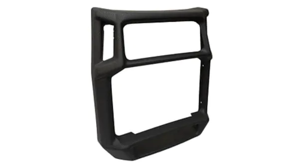
In a thick-wall forming program the mold usually takes the blame for slow cycles, but the cooling circuit inside it does most of the deciding. Channels set too far apart leave hot bands across the sheet; channels set too close to the surface print witness marks onto cosmetic parts; coolant that is too cold condenses water onto the tool between shots. This guide walks through the channel geometry, coolant settings, failure modes, and validation steps that matter for heavy-gauge vacuum forming and thermoforming of sheet in the 3–15 mm range, where heat removal rather than machine speed sets the pace of production.
- Cycle time in heavy-gauge thermoforming is set by how fast heat leaves the thickest section of the part, not by how fast the machine moves.
- Channel diameter, distance below the forming surface, and pitch interact; changing one without the others shifts temperature uniformity across the sheet.
- Coolant temperature must match the material. Over-chilling thick sheet freezes the skin while the core is still hot, which locks in warpage.
- Keep every circuit turbulent and hold the water temperature rise across each circuit to about 5 °C, or the far end of the mold runs hot.
- Separate zones for cavity, plug, and flange let you balance cooling without re-cutting the mold.
- Validate with a paper heat balance plus a prototype forming run before committing production tooling.
Why Do Cooling Channels Control Cycle Time in Thick Wall Thermoforming?
Because the formed part can only leave the mold as fast as heat leaves the sheet. In thick-wall thermoforming, the thermal mass of each part is several times higher than in thin-gauge work, so most of every cycle is conduction time rather than forming time. A well-designed circuit shortens that conduction stage without shocking the sheet surface.
Heat has to travel from the core of the sheet, through the outer layers, across the mold wall, and into the coolant. The first leg is fixed by physics: most polymers conduct heat at roughly 0.2 W/m·K, an order of magnitude below the aluminum around them, so the sheet itself is the bottleneck and no channel layout can rush it. What channel design controls is the second bottleneck — how quickly and how evenly the mold surface carries heat away. If the surface temperature varies across the part, the sheet freezes at different rates and the geometry locks in with built-in stress.
The target is to release the part while it is rigid enough to hold shape but not so hot that it sags or grips the tool. Two material benchmarks frame that window. ASTM D648 specifies the standard test method for the deflection temperature of plastics under flexural load, and it is commonly used to confirm that a formed enclosure or structural panel will hold its geometry at the temperature where it is ejected from the tool.1 ISO 306 defines the Vicat softening temperature test, which indicates the sheet temperature at which a formed panel begins to sag under its own weight — the practical ceiling for how warm a part can be at release.2
ZetarVac runs more than 20 vacuum forming and thermoforming machines and processes sheet from 0.5 to 15 mm, with forming lengths up to about 2,500 mm. Across that gauge range, one coolant setpoint cannot serve every tool: a 2 mm tray and a 12 mm equipment housing carry very different heat loads, so circuit layout and coolant settings are specified per mold rather than per machine.
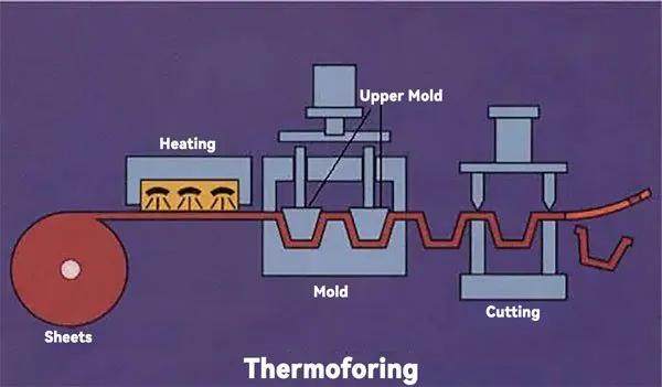
For a broader view of the process itself, see our vacuum forming overview; the rest of this article stays inside the tool. The starting point for any cooling discussion is the map of where the heat actually sits after forming, which the diagram below summarizes.
How Deep, How Wide, and How Close Should Channels Be?
Start from sheet gauge. A conventional starting point for aluminum production tooling is drilled channels of 8–12 mm diameter, positioned 15–25 mm below the forming surface, with center-to-center pitch of roughly two to three times that depth. These are engineering rules of thumb, not laws; the final numbers depend on material, part geometry, and the machine’s coolant supply.
Each parameter trades against another. Moving a channel closer to the surface speeds heat removal but widens the temperature difference between the metal directly over the channel and the land between channels. The sheet above the land stays hotter, which can appear as gloss variation on cosmetic parts and as thermal fatigue cracking in the tool over time. Widening the pitch does the same thing more cheaply but less evenly. Larger bores move more water at lower pressure drop, but a production mold has limited wall thickness to sacrifice, especially around tight radii and clamp frames.
Geometry decides where the channels have to concentrate. Deep-drawn parts pile up material at the corners as the draw ratio increases3, so the thickest and slowest-cooling sections are usually not in the middle of the panel. The circuit should follow that map, with extra passes or higher flow near deep corners and separate attention on the plug side, which forms the inside surface of the part. How the tool is split matters here; our guide to positive and negative molds explains why plug and cavity see different heat flows.
The table below collects conventional starting ranges used across heavy-gauge toolmaking.
| Parameter | Conventional starting range | What it trades against |
|---|---|---|
| Channel diameter | 8–12 mm drilled; cast-in coils for large cast tools | Larger bores move more water but thin the mold wall |
| Distance below forming surface | 15–25 mm | Closer cools faster but increases surface temperature swing and witness marks |
| Center-to-center pitch | 2–3 × surface distance | Wider pitch leaves hot bands between channels |
| Circuit segmentation | Cavity, plug, and flange as separate zones | More zones cost plumbing but allow balancing |
| Water temperature rise per circuit | ≤ 5 °C | A large rise means flow is too low or the circuit is too long |
Even a well-drawn circuit is a compromise, and the most common compromise is made in the wrong direction. Two judgments separate a tool that runs for years from one that fights the operator every shift.
"Cooling channels should sit as close to the mold surface as possible for the shortest cycle."False
Surface distance trades cooling speed against uniformity and tool life. Channels set too close create large temperature swings between channel crowns and lands, which prints gloss variation onto cosmetic surfaces and cracks thin mold walls through repeated thermal cycling.
"Surface distance is set by uniformity first, then shortened as the material allows."True
For structural parts in PP or HDPE, a designer can move channels closer and keep the cycle savings. For cosmetic ABS or PC housings, keeping enough metal between channel and surface to average out the temperature field is usually worth more than the seconds it costs.

What Coolant Temperature and Flow Actually Work?
Set coolant temperature by material, not by habit. As conventional starting points, mold surfaces for ABS often run near 50–70 °C, PC near 70–90 °C, and PP or HDPE near 40–60 °C. The final setpoint is confirmed on the tool because it depends on sheet gauge, part geometry, and the cycle the program needs.
Flow matters as much as temperature. Coolant must move fast enough to stay turbulent, because a laminar boundary layer insulates the channel wall exactly where heat transfer is needed. A conventional target is a Reynolds number above roughly 5,000 in every circuit.4 Just as important is the temperature rise across the circuit: if water enters at 60 °C and leaves at 70 °C, the far end of the mold runs ten degrees hotter than the near end, and the part will show it. Holding the rise to about 5 °C usually means splitting long series circuits into parallel zones fed from a manifold.
There is also a floor, not only a ceiling. Coolant below the workshop dew point condenses water on the mold surface between shots, and that moisture prints onto the next part or causes the sheet to stick locally. In humid seasons this failure is easy to misread as a material problem. Keep setpoints above dew point or dry the air around the press.
"Running coolant at the lowest achievable temperature always shortens the cycle."False
Over-chilled surfaces freeze the outer skin while the core of a thick sheet is still hot, locking in differential shrinkage. The result is warpage after release and parts that drift out of tolerance as they continue cooling and shrinking toward their final dimensions.
"Coolant temperature is matched to the material's freezing behavior, not minimized."True
The fastest stable cycle cools all layers of the sheet at a similar rate. That often means warmer water than intuition suggests for thick engineering sheet, trading a slightly longer cycle for flat, dimensionally stable parts.
The material side of this decision is wider than most buyers expect.
The plant’s material library spans ABS, PC, HDPE, LDPE, PP, PMMA, PC/ABS, ASA, and glass-filled PP, among other grades. These resins differ in specific heat, thermal conductivity, and deflection temperature, so an identical channel layout can cool a PP industrial tray efficiently while leaving a PC medical housing cycle-bound. Coolant setpoints and circuit balancing are therefore specified per material and per tool.
Where Does Uneven Cooling Show Up on the Finished Part?
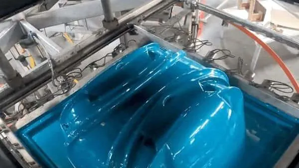
Uneven cooling shows up as geometry errors long before anything breaks. The typical evidence is warpage after release, corners that spring out of tolerance, gloss bands that mirror the channel layout, and parts that pass first inspection but drift out of tolerance as they finish cooling to room temperature.
Warpage is the most expensive symptom because it is discovered downstream. When one region of the sheet freezes well before another, the early region stops shrinking while the later region continues, and the finished part bows toward the side that froze last. On deep parts the thick corners are usually last to cool, so corner spring-back and out-of-square flanges are the classic signature of a circuit that under-serves the corners.
Surface symptoms are cheaper to catch. Gloss or witness marks that trace the channel pattern mean the surface temperature is oscillating between channel crowns and lands5 — most visible on PC and PMMA covers, where clarity magnifies every surface irregularity. Local sticking, where the part hesitates on release at one spot, marks a hot zone on the tool. An infrared camera on the sheet immediately after forming, or a thermocouple grid on the mold surface once it reaches steady state, maps hot bands in minutes; a re-measure of the same parts once they have fully cooled then confirms whether frozen-in stress will relax into a tolerance problem.
Two judgment calls come up repeatedly when buyers review cooling proposals.
"One well-sized spiral channel around the cavity is enough cooling for a 10 mm sheet."False
A single long circuit carries a large water temperature rise from inlet to outlet, so one side of the mold runs hotter than the other. Thick sheet amplifies that imbalance into visible bow and corner spring-back across the part.
"Thick-wall parts need zoned circuits with independent flow or temperature control."True
Separating cavity, plug, and flange into independently metered zones lets the molder trim each region against the part’s actual geometry. The extra plumbing is minor next to the cost of reworking warped housings or trays.
How Do You Validate a Cooling Design Before the Mold Is Cut?
Combine a paper heat balance with a prototype forming run. Estimate the heat load per shot from sheet mass and target ejection temperature, size the total coolant flow from that load, then confirm the layout on a prototype tool by mapping surface temperature and measuring parts once they have fully cooled.
The paper step is simpler than it sounds. Heat per shot is roughly sheet mass times specific heat times the temperature drop from forming to ejection; divided by cycle time, that gives the kilowatts the coolant must absorb, and the required water flow follows from the 5 °C allowable rise. This arithmetic shows whether the channel plan can physically carry the heat with the machine’s supply before a single hole is drilled.
The physical step matters more for heavy-gauge work because thick sheet hides imbalance until parts are measured. Prototype and plaster tooling lets you form real parts at real gauges and find hot bands early; our article on plaster thermoforming molds explains where these low-cost tools fit. Dimensional checks at ejection, after full cooling to room temperature, and after trimming give the earliest warning that a circuit needs re-balancing before production tooling is cut.
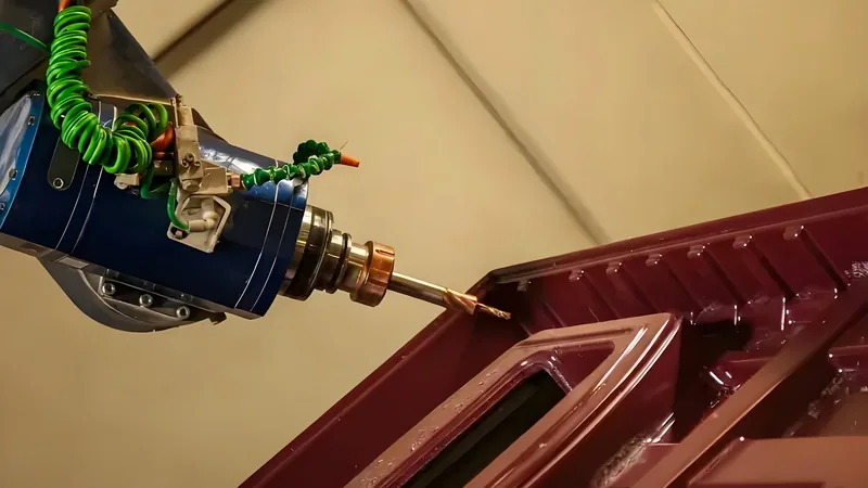
ZetarVac supports prototyping, small batch, and large batch production, with reference monthly capacity of about 100,000–200,000 pieces across more than 45 production lines, and formed parts are trimmed on a 5-axis CNC centre so the outline follows the forming tool. At that volume, a cooling fault that quietly adds ten seconds per cycle becomes one of the largest cost lines in the program, which is why cycle validation belongs in the prototype stage rather than after ramp-up.
FAQ
Does a male or female mold need different cooling?
Yes, and the plug side is usually the harder one. The cavity can be drilled or fed almost anywhere, while a male plug leaves less room for channels and forms the inside surface that cools last on deep draws. Prioritize the plug circuit on deep parts and expect the cavity to follow its timing.
Can cooling channels be added to an existing mold?
Sometimes. Machined aluminum tooling with sufficient wall thickness can usually accept additional drilled circuits and plugged crossovers. Cast tooling with embedded coils is far less forgiving, and any repair near a cooling passage risks leaks, so treat the request as an engineering review rather than a machining errand.
How do I know if my cycle is cooling-limited?
Check part temperature at ejection against the material’s deflection temperature and watch the part after release. If parts sag on the trim fixture, bow after trimming, or force operators to wait far longer than forming itself takes, the circuit rather than the machine is setting the pace.
What maintenance do thermoforming mold cooling circuits need?
Treat circuits like any water system: log flow and pressure drop periodically, flush scale and biofilm, and inspect O-ring plugs and couplings for seepage. A circuit that slowly loses flow shows up first as gradually growing cycle time, which is easy to miss if nobody records it.
If you are evaluating suppliers for a thick-wall program, share your drawings, sheet material, and target cycle time with ZetarVac through our China vacuum forming manufacturer page, or review the full service scope and talk to an engineer about your cooling design before tooling is cut.
-
Heat deflection temperature (HDT): The temperature at which a standard plastic bar deflects a specified amount under a defined flexural load, used to judge the upper service temperature of a formed part. ↩
-
Vicat softening temperature: The temperature at which a flat-ended needle penetrates a plastic specimen to a defined depth, indicating the onset of softening. ↩
-
Draw ratio: The ratio of formed part depth to a characteristic mold dimension, used to estimate sheet thinning in deep-drawn thermoforming. ↩
-
Reynolds number: A dimensionless ratio of inertial to viscous forces in a flow; values above roughly 4,000 indicate turbulent flow in a pipe. ↩
-
Witness marks: Surface imperfections on a formed part that reproduce mold features or temperature variations, typically seen as gloss bands or slight ridges. ↩