
Wall thickness distribution is the most common technical argument between buyers and thermoforming suppliers. A heavy gauge part can pass a visual check and still come out 40 percent thinner in one corner than at the flange, and that corner is exactly where the part fails in service. This guide explains why uneven wall thickness happens in heavy gauge thermoforming, which process and mold levers actually move material, and how to verify the result before production tooling is committed.
- Uneven wall thickness comes from differential stretch: wherever the sheet touches the mold first it freezes and stays thick, while the last areas to form end up thinnest.
- Sheet sag and heater zone balance create a non-uniform starting point before the mold even closes.
- Corners, deep draws and webbing zones thin fastest; a draw ratio above roughly 1.5–2:1 in heavy gauge work calls for plug assist or redesign.
- The highest-value fixes are preheat balance, forming temperature, vacuum rate and plug geometry — not simply buying thicker sheet.
- Wall thickness is measured, not assumed: ultrasonic gauging and cut section checks belong in every first article inspection.
- Specifying target wall ranges per zone on the drawing prevents most downstream disputes.
Why Does Uneven Wall Thickness Happen in Heavy Gauge Thermoforming?
Uneven wall thickness happens because a thermoformed part is made by stretching a hot sheet, and a hot sheet never stretches uniformly. Wherever the sheet contacts the mold surface first, it cools, grips and stops moving; wherever it has to travel farthest or turn through tight geometry, it thins the most.
In vacuum forming, the pattern is predictable. Flat flanges and clamped edges stay close to the original sheet gauge because they barely move. Radii, corner transitions and the floor of deep pockets can lose 30–50 percent of nominal thickness on a demanding draw. Male, or positive, molds generally hold side walls thicker than female, or cavity, molds because the sheet drapes over the tool instead of being pulled down into it. If you need a refresher on the mechanics, the vacuum forming overview covers the process step by step.
Sag adds a second variable before forming even starts. A sheet heated past its softening point sags under gravity, and the center sags more than the clamped edges, so the sheet is already non-uniform when the mold rises.1 Materials with a wide softening range, such as ABS and PC/ABS, tolerate a broader heating window than PMMA or PC, where a few extra degrees of heat show up quickly as marks and thin patches.
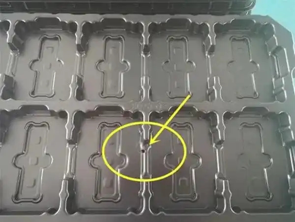
The practical consequence is that wall thickness is never one number. It is a map across the part, and every heavy gauge drawing should be reviewed with that map in mind.
ZetarVac processes sheet from 0.5 to 15 mm and forms parts up to about 2,500 mm long. That range spans the window where sag control and heater zoning stop being optional, because on a long, thick sheet uneven preheat shifts local wall thickness before the vacuum is even applied.
How Preheat and Sag Decide the Outcome Before the Mold Closes
Most thin-corner complaints trace back to the oven, not the mold. On machines with zoned top and bottom heater banks, if the edge zones run cooler than the center, the sheet enters forming with a thick rim and a thin middle — the exact opposite of what a deep draw needs.
Two setup habits keep preheat honest. First, heat to forming temperature rather than to sag alone: sag tells you the sheet is soft, not that it is even. Second, give the sheet a short soak so core temperature catches up with surface temperature, especially on sheet above about 6 mm, where the surface reads hot long before the center does.

For geometry that needs extra control, a pre-stretch bubble helps. Blowing a controlled bubble before the mold rises spreads the thinning that would otherwise concentrate in the deepest zones, and paired with a balanced oven it is the cheapest wall distribution tool available. Getting these two steps right routinely shifts corner thickness back toward nominal before any tooling change is even discussed.
Where Does a Vacuum Formed Part Thin Out First?
Corners, deep draw walls and webbing zones thin first, in that order. An inside corner stretches material in two directions at once, deep straight walls stretch it along the draw direction, and webs form where excess sheet folds against itself in unsupported spans.
Corners and radii take the worst combination: two-directional stretch plus early freeze-off. Increasing an inside radius from a few millimeters to 8–10 mm or more on heavy gauge parts gives the sheet a path to slide into the corner instead of stopping short of it. Deep draw walls thin progressively from top to bottom on a female mold, so the drawing should state where in the wall the minimum applies. Webs and wrinkles are the opposite failure — excess material folding in unsupported areas — and they usually point to a draw ratio problem rather than a heating problem.2
"A thicker starting sheet will fix thin corners on its own."False
Up-gauging shifts the whole distribution upward but does not change the relative stretch, so corners stay proportionally thin while flanges get oversized. You pay more for material and then machine most of the extra weight away.
"Draw ratio predicts whether a corner will thin out before tooling is cut."True
Comparing the developed surface length to the sheet length in the worst zone gives a draw ratio that estimates local stretch. Above roughly 1.5–2:1 in heavy gauge work, plan on plug assist or a geometry change instead of hoping process tweaks will save the corner.
Draw ratio is easy to estimate at the quote stage from the part model, which is why it belongs in every supplier conversation before tooling money is spent.
Which Process Parameters Actually Move Material?
Four levers do most of the work: heater zone balance, forming temperature, vacuum rate and plug assist geometry. Mold temperature and the trimming strategy refine the distribution, but they rarely rewrite it.
| Lever | What it changes | Typical effect on wall distribution | Best used when |
|---|---|---|---|
| Heater zone balance | Preheat uniformity across the sheet | Evens the baseline and reduces center sag | First adjustment for any thin-corner complaint |
| Forming temperature | How far the sheet stretches before freezing | Hotter sheet follows detail but thins more overall | After preheat is balanced, not instead of it |
| Vacuum rate and sequence | Where material lands as the sheet forms | Slow pull lets the sheet slide and keeps floors thicker | Deep draws and webbing-prone geometry |
| Plug assist | Mechanically pushes stock into last-formed zones | Adds thickness at corners and pocket floors | Draw ratios above roughly 1.5–2:1 |
| Mold temperature | Timing of skin formation on the tool surface | Warmer tools delay freeze-off in thin zones | Detailed thin areas on PC and PMMA parts |
The order matters as much as the levers themselves. Balance the oven first, then set forming temperature, then tune the vacuum sequence, and only then reach for plug or mold changes. Chasing a thin corner with plug geometry while the oven runs cold wastes trial shots and muddies the data.
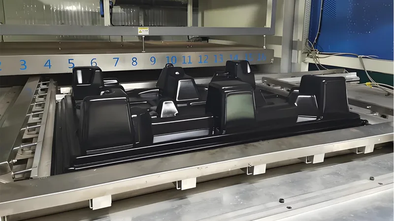
On thick sheet, slower vacuum beats harder vacuum in most cases: a controlled pull gives the material time to keep flowing toward the deepest zones instead of freezing in place. Our companion piece on wall thickness reduction in heavy gauge thermoforming works through each lever with concrete examples.
How Do You Measure and Verify Wall Thickness?
Measure it three ways: non-destructive ultrasonic gauging on the part, destructive cut section checks at agreed zones, and a documented first article that records the numbers. Average wall alone proves nothing — the distribution map is what predicts performance.
Mark the critical zones on the drawing before the first trial: flange, side wall top and bottom, inside corners, pocket floor. Ultrasonic gauging suits routine monitoring and incoming checks; cut sections give the definitive record for validation because they show the full gradient, not spot readings. In vacuum forming production, thickness belongs on the sampling plan alongside dimensional checks, not just on the drawing.
When the part is structural, wall data should be paired with property validation. ISO 527-2 specifies the standard tensile test for plastics, and it is the test behind the data sheets you compare when thin corners reduce the load-bearing cross-section of a formed panel.3 For broader context on forming practice and quality discussions, the SPE Thermoforming Division publishes practical industry guidance for engineers and processors.
"A passed first article proves wall distribution is stable for volume production."False
A first article reflects one sheet lot, one oven condition and one operator on one day. Sheet lot changes and heater drift move the distribution over time, so thickness must be re-checked on a sampling plan rather than assumed from a single approval.
"Wall thickness belongs on the control plan, not only on the drawing."True
Specify target ranges per zone and a sampling frequency tied to sheet lot changes. That is what turns a one-time measurement into stable output across months of running production.
A structured first article is the natural place to capture zone-by-zone thickness; our first article inspection checklist for heavy gauge thermoformed parts lists the zones and records worth standardizing.
When Should You Redesign the Part or the Mold Instead?
Redesign when process tuning has hit its limit: draw ratios beyond what plug assist can serve, inside radii under about 3 mm on heavy gauge sheet, or deep draws with no transition feature. Fixing geometry at the design stage costs days; chasing it with process variables costs weeks of trials.
The highest-leverage changes are unglamorous: increase radii, add draft, insert a step to break up a deep draw, move a cosmetic surface away from the deepest zone. Material choice interacts with all of this. For enclosures, ASTM D648 specifies the test that determines a plastic’s deflection temperature under flexural load, and it bounds how thin a wall can go before heat distortion, rather than impact, becomes the limiting failure mode.4
With more than 20 vacuum forming machines and 45+ production lines across the plant, forming and trimming stay under one roof, including 5-axis CNC trimming of formed parts. Keeping both in-house matters here because trimming and fixture errors are often misread as wall thickness problems during inspection.
A structured design review catches most of these issues before steel is cut. The DFM checklist for heavy gauge thermoformed parts and molds works well as a pre-quote filter for both new parts and problem parts.
FAQ
How much wall thickness variation is acceptable on a heavy gauge part?
It depends on the function of each zone, not on the part as a whole. A common engineering approach keeps cosmetic flanges within a moderate percentage of nominal while defining a hard minimum at load-bearing corners; what matters is that the drawing states the zones and the numbers instead of one blanket tolerance.
Can uneven wall thickness be fixed without changing the mold?
Often yes, if the cause is thermal. Rebalancing heater zones, adjusting forming temperature and slowing the vacuum sequence routinely improves distribution within a few trial shots. If the thin zone sits at the bottom of a deep draw with a high draw ratio, a plug or geometry change is usually unavoidable.
Does thicker sheet automatically solve thin corners?
No. Up-gauging lifts the entire distribution but leaves the relative thinning pattern unchanged, so the corner remains the weakest point while flanges get heavy and expensive. Fix the stretch pattern first, then choose the sheet gauge for stiffness and cost.
What should I send a supplier for a wall thickness review?
Send the part drawing with target wall ranges per zone, the material and gauge, the application temperature and load conditions, and photos of any problem areas. With that, an engineer can estimate draw ratios and flag risks before tooling is quoted. If you are comparing suppliers for a formed enclosure, housing or tray, share your drawings and talk to an engineer — a factory that forms and trims under one roof can review the wall distribution with you before any steel is cut.
-
Sag: The downward drape of a heated plastic sheet under gravity during preheating, which makes the sheet non-uniform before forming begins. ↩
-
Draw ratio: The ratio of formed surface area to original sheet area in a given zone; higher values mean more local stretch and thinner walls. ↩
-
ISO 527-2: The ISO standard specifying the test method for determining the tensile properties of plastics, including rigid sheets and formed parts. ↩
-
HDT: Heat deflection temperature, the temperature at which a plastic test bar deflects a defined amount under flexural load, measured per ASTM D648. ↩