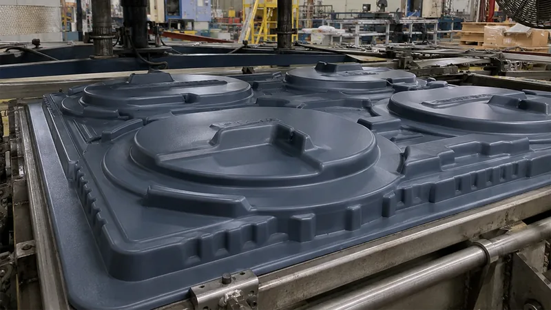
Warpage and springback are the two distortion problems that quietly erode margin on heavy-gauge vacuum forming programs. The part looks right coming off the machine, then measures out of tolerance on the assembly line days later. Both defects trace back to residual stress locked into the sheet during forming, and both are manageable when you treat them as predictable process physics rather than bad luck.
- Warpage is non-uniform shrinkage across the panel, while springback is elastic recovery once the part leaves the tool.
- Residual stress built up during heating, stretching, and cooling is the root cause of both.
- Thick sheet, deep draws, and large flat areas raise distortion risk in different ways.
- The fix lives in sheet temperature uniformity, cooling balance, and tool geometry, not in a late rework step.
- Flatness data is only meaningful after the part has fully cooled and stabilized at room temperature.
- Standards such as ASTM D790 and ISO 75-2 give buyers and suppliers a shared language for stiffness and heat resistance data.
What Causes Warpage in Thermoformed Parts?
Warpage in thermoformed parts is non-uniform shrinkage: different zones of the sheet contract by different amounts after forming, so the panel bows toward the side that shrank more. The residual stress1 driving it comes from three places — uneven sheet heating, molecular orientation from stretching, and asymmetric cooling between the mold side and the free side.
Infrared heater banks rarely deliver perfectly even sheet temperature across a full sheet, especially near the clamp frame where heat escapes into the rails. Hotter zones stretch further, thin out, and then shrink more on cooling. The classic symptom is twist that concentrates near the sheet corners, long after anyone has blamed the tool. Heater zone mapping and a repeatable oven profile are the first levers, and they cost nothing but discipline.
Molecular orientation is the second mechanism. As the sheet stretches over the tool, polymer chains align along the draw direction; that alignment freezes in on cooling and relaxes slightly afterwards, pulling the part back toward its pre-formed shape. Deep, uneven draws create the strongest orientation gradients, which is why distortion concentrates where draw depth changes abruptly.
Cooling asymmetry is the third driver. The tool side of the part cools quickly against metal, while the free side cools slowly in moving air. The two surfaces solidify at different times and contract by different amounts, which crowns large flat panels toward the slow side. Balanced mold temperature and directed free-side airflow are the standard countermeasures.
Material shrinkage sets the ceiling on what any of the above can achieve. Semi-crystalline resins such as PP and HDPE contract far more than amorphous resins like ABS, PC, or PMMA — mold shrinkage for PP can run several times that of ABS depending on grade and gauge2. The fundamentals of heating sheet, stretching it over a tool with vacuum, and cooling the formed shape are well documented by industry bodies such as the SPE Thermoforming Division.
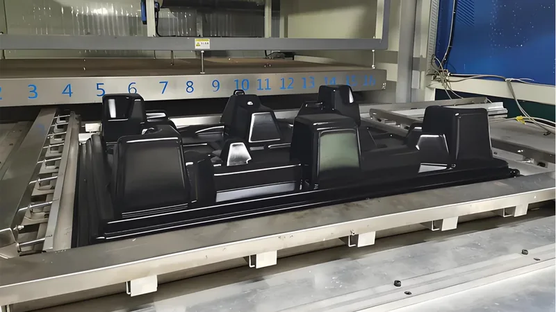
ZetarVac processes sheet from 0.5 to 15 mm and forms parts up to about 2,500 mm long. Heavy-gauge sheet holds considerably more heat than thin stock, so on thick parts the cooling cycle — not the forming step — usually decides whether a large panel stays flat.
In practice the three mechanisms overlap, and no single one explains a warp on its own. Effective countermeasures therefore combine heater discipline, cooling balance, and material selection rather than chasing one variable at a time.
"A part that measures flat coming off the machine will still measure flat in assembly."False
Residual stress keeps relaxing for hours or days after forming, so early measurements capture only part of the distortion. Panels that pass inspection on the press floor can fail flatness checks the next morning.
"Flatness should be verified after the part has fully cooled and stabilized."True
Residual stress keeps relaxing and shrinkage keeps completing until the part sits at a stable room temperature. Measuring at that point produces data that matches what your customer will actually see during assembly.
Why Do Parts Spring Back After Forming and Trimming?
Springback is elastic recovery: polymer chains oriented during stretching try to return toward their original state once the tool releases them, so walls bow outward, flange angles open up, and draft effectively disappears. Where warpage is a shrinkage problem, springback is a stress-relaxation problem, and it shows up most on deep draws and tall vertical walls.
Geometry decides how much recovery you get. Deep draws, tall walls, and tight inside radii store more elastic energy than shallow pans with generous radii. Holding the part in the tool through the final phase of cooling lets the walls set before the constraint disappears; releasing too early banks recovery that shows up the moment the part comes free.
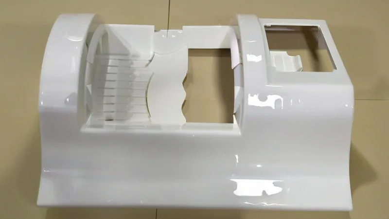
Trimming can also wake a part up. Cutting forces and the loss of constraint near flange edges let residual stresses rebalance, and edges can pull in or flare after machining. Trimming after the part is fully cooled and settled — standard practice for CNC trimming and secondary operations on thermoformed parts — keeps the trimmed outline matching what assembly will actually receive.
With a maximum forming length of about 2,500 mm, even half a degree of angular springback moves the edge of a panel by roughly 20 mm. On parts of this size, springback has to be engineered out of the tool, not corrected afterwards.
The practical consequence is that springback is predictable. It follows geometry and thermal history, which means it can be estimated at the design stage and compensated in the tool, instead of being discovered after the first shipment.
"Turning up the vacuum is the fastest way to pull a warped part flat."False
Vacuum only presses the sheet against the tool while it is hot and soft. It cannot change how the sheet cools or how stress distributes, so a distortion problem rooted in temperature gradients will reappear every cycle.
"Flatness is controlled by sheet temperature uniformity and cooling balance."True
Zoned heater settings, verified sheet temperature, and matched mold-side and free-side cooling remove the root causes of bowing. Vacuum level then only needs to guarantee full contact with the tool detail.
Which Design and Tooling Choices Reduce Distortion?
Most distortion is decided before the first sheet is heated. Draft angles, radii, wall height, and the choice between a male and female tool determine how much elastic energy the part can store and how evenly it cools.
Practical rules that hold across most heavy-gauge projects: add 1–2 degrees of draft beyond the minimum you think you need, use inside radii of at least half the sheet thickness, and avoid long unsupported flat spans where a slight crown or a rib pattern can absorb shrinkage instead of fighting it. On deep parts, pre-stretching the sheet distributes thinning and orientation more evenly, which directly reduces the differential stress that later reads as warp.
Tooling detail matters just as much. Zoned mold temperature control, cooling channels placed where the part is thickest rather than where they are easiest to machine, and adequate venting all shorten and even out the cooling phase. Surface texture helps too: a light texture masks the small waves that flat glossy surfaces exaggerate, and the finish you choose for a vacuum formed part can be selected partly for that reason.
| Distortion mode | Typical root cause | First-line countermeasure | How to verify |
|---|---|---|---|
| Center bow on large panels | Cooling asymmetry between mold side and free side | Balance mold temperature and extend free-side cooling | Surface plate and feeler gauge after full stabilization |
| Flange flare-out | Elastic recovery of deep-drawn walls | Add draft, open radii, hold in tool longer | Angle check against a checking fixture |
| Corner twist | Uneven sheet heating near the clamp frame | Re-zone heaters, verify oven profile sheet to sheet | Corner-to-corner height on a granite table |
| Hole-to-hole growth | Post-trimming stress relaxation | Trim fully cooled parts, stabilize critical features | CMM on trimmed parts after stabilization |
"A first article that passes inspection proves the process will hold tolerance in production."False
A first article is a single snapshot taken early in the run. Shrinkage and stress relaxation continue after forming, so stability has to be confirmed over time and across the batch, not from one part.
"Dimensional stability should be confirmed on parts measured after full stabilization."True
Re-measuring trimmed parts once they have fully cooled and settled captures post-forming relaxation and gives numbers that hold up in assembly. That practice catches drift a single first-article report will miss.
How Do You Set the Process Window for Flat Parts?
Sheet temperature is the master variable. Typical forming ranges are roughly 140–170 °C for ABS, 160–190 °C for PC, and 150–175 °C for PP, but the correct number depends on gauge, resin grade, and the machine in front of you — these are engineering starting points, not recipes. The target is not maximum heat; it is even heat, verified with a scanned sheet rather than assumed from heater settings.
Mold temperature and cooling time come next. Tools for heavy-gauge work commonly run warm — roughly 40–80 °C depending on resin — because a cold tool freezes the surface while the core is still soft and banks stress into the part. Cooling time scales steeply with thickness, so a 10 mm panel needs several times the cooling of a 3 mm one, and cutting that phase short is the fastest way to buy warpage.
Vacuum and forming pressure deserve realistic expectations. Full vacuum during forming guarantees contact and detail, but no vacuum level changes how the sheet cools afterwards. Pressure forming sharpens definition on textured tools, yet distortion control still lives in the thermal part of the cycle.
For parts with demanding flatness requirements, a post-forming stabilization step helps. Holding parts below their heat deflection range for a controlled period relaxes residual stress before the customer ever sees the part. Annealing is not free, so it belongs on parts where drawing flatness is tighter than the natural shrinkage of the resin allows.
ZetarVac runs more than 20 vacuum forming machines across a plant with over 45 production lines. Once a distortion-resistant process window is locked on the first machine, the parameters can be duplicated line to line so mid-volume and volume batches behave like the approved sample.
How Should You Validate Flatness in Production?
Flatness data is only real once the part has stabilized: measure after the part has fully cooled and equilibrated at room temperature, and later still for PP, which continues to crystallize and shrink as it ages. For most engineering resins, distortion levels off once the part reaches room temperature and stays there. Measuring hot parts straight off the press produces numbers that will not survive the week.
Practical inspection uses a surface plate with feeler gauges for panels, dedicated checking fixtures for repeat parts, and a CMM where hole positions interact with flatness. Trend flatness across the batch rather than judging a single part, and re-check trimmed parts alongside formed ones so trimming effects are visible separately.
Two standards do most of the talking here. ASTM D790 defines the standard flexural test for plastics, and flexural data from sheet and formed panels tells you how much stiffness a geometry has to resist bowing under its own residual stress and service loads3. ISO 75-2 specifies the heat deflection temperature test for plastics under load, which indicates the temperature limit at which a formed enclosure loses stiffness; a housing used near or above that range relaxes residual stress in service and distorts further45.
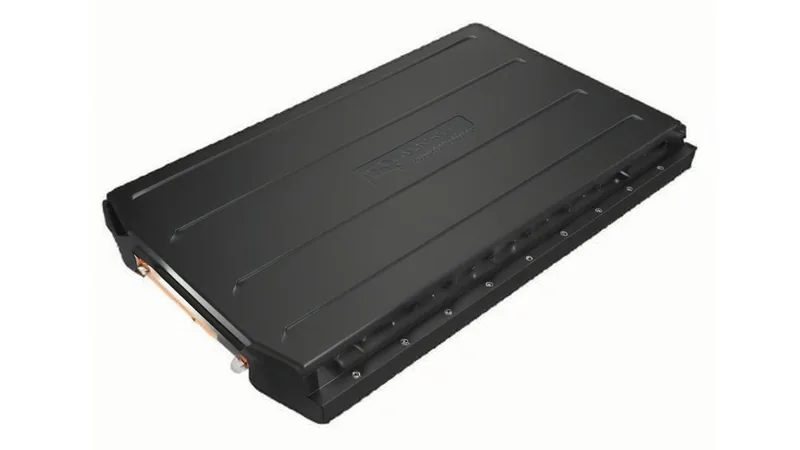
Documentation closes the loop. Record sheet batch, oven profile, cycle time, and measurement results together, so when distortion appears three months later you can tell a material change apart from process drift. Suppliers who can show that traceability are far easier to qualify for distortion-sensitive programs.
FAQ
How much warpage is acceptable on a thermoformed part?
There is no universal number; acceptable flatness depends on function, not on the process. Large cosmetic panels are commonly specified within roughly 1–3 mm per metre of span, while sealing surfaces and mounting faces get their own tighter local callouts. Put the tolerance where the part works and state it on the drawing rather than leaving it to shop-floor judgement.
Does thicker sheet warp more or less?
Both, for different reasons. Thick sheet is stiffer and resists bowing, but it holds far more heat, so through-thickness temperature gradients are larger and cooling takes much longer. Without balanced cooling, heavy-gauge parts are usually more distortion-prone than thin ones, not less.
Can a warped thermoformed part be corrected after forming?
Sometimes, marginally. Re-heating and press-flattening can recover small bows, but the treatment re-introduces stress and the part tends to creep back. Flattening belongs in development as a diagnostic, not as a production rescue step; if you need it every shift, the tool or the cooling cycle needs to change.
Which materials warp least in vacuum forming?
Amorphous resins — ABS, PC, PMMA, and blends such as PC/ABS — shrink less and more predictably than semi-crystalline resins such as PP and HDPE, so they hold flatness more easily. Filled and reinforced grades reduce shrinkage further at the cost of different processing behavior. Material choice and geometry should be decided together, not separately.
How long should I wait before measuring flatness?
Measure after the part has fully stabilized at room temperature, not straight off the machine. For PP and other semi-crystalline resins, allow extra time because crystallization continues after forming and the part keeps shrinking slightly. Specify the same conditioning on the drawing so supplier and customer measurements stay comparable.
If you are evaluating suppliers for a distortion-sensitive part, share your drawings and ask directly how the tool and cooling cycle will be engineered for your geometry. Review your part with our vacuum forming team or see our full service range to start the technical conversation.
-
Residual stress: Stress frozen into a formed part during stretching and cooling that stays locked in after forming and relaxes over time, driving distortion. ↩
-
Mold shrinkage: The percentage contraction of a plastic as it cools from forming temperature to room temperature, a main driver of warpage. ↩
-
ASTM D790: Standard test method for flexural properties of plastics, used to characterize the stiffness of sheet and formed panels and enclosures. ↩
-
ISO 75-2: Standard that specifies the heat deflection temperature of plastics under flexural load. ↩
-
Heat deflection temperature (HDT): The temperature at which a plastic specimen deflects a defined amount under a specified flexural load. ↩