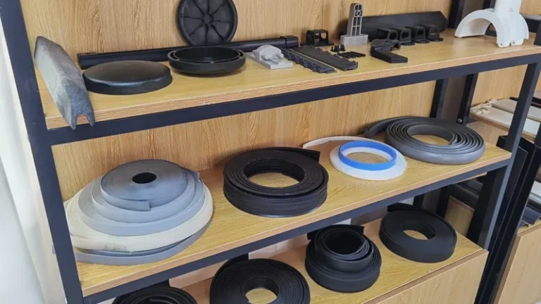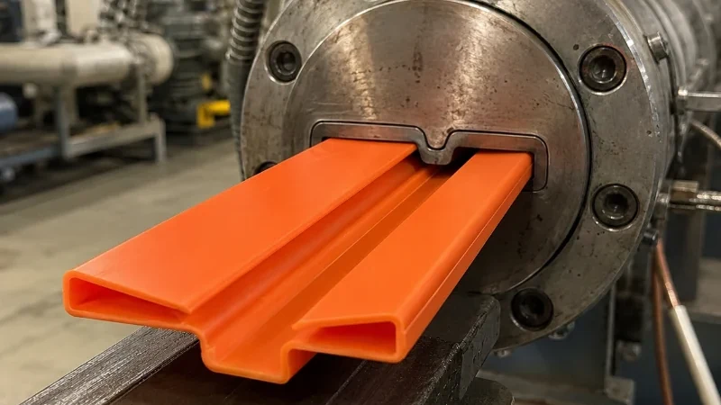
In plastic profile extrusion, the difference between a stable production run and a stream of rejects comes down to a handful of process parameters. Melt temperature, screw speed, vacuum calibration, cooling and haul-off speed interact continuously, so adjusting one without checking the others rarely holds for long. This guide walks through each parameter, gives commonly used working ranges, and explains how to verify the result before committing to volume production. It focuses on profile work; for the wider process family, see our overview of plastic extrusion molding.
- Melt temperature must sit inside the compound’s processing window; hotter is not better and accelerates degradation.
- Vacuum calibration, not the extrusion die alone, fixes the final dimensions after the melt leaves the tooling.
- Haul-off speed and extruder output must stay matched to hold wall thickness along the profile.
- Co-extrusion adds a second set of variables: layer ratio, viscosity match and interface temperature all need control.
- A passing first article proves dimensional conformance once; capability data over a full run proves stability.
- Verification means repeated measurement of the actual cross-section, not a single sample at line start.
What Are the Core Parameters in Profile Extrusion?
The core parameters are barrel and die zone temperatures, screw speed, vacuum level in the calibration sleeve, cooling water temperature and haul-off speed. Each acts on melt quality, dimensional accuracy or surface finish. Because they interact, a profile extrusion line is tuned as a system rather than dial by dial.
Every parameter has a workable band rather than a single correct number, and those bands are engineering conventions for the compound class in question. Where the numbers should sit comes from the compound supplier’s stated processing window, the section geometry and the specific machine.
| Parameter | Where it is set | Primary effect | Failure when wrong |
|---|---|---|---|
| Melt temperature | Barrel and die head zones, inside the compound’s processing window | Melt homogeneity and surface finish | Degradation, discoloration, brittle scrap |
| Screw speed | Extruder drive, trimmed in small steps against target output | Throughput and shear heating | Output surging, over-sheared melt |
| Vacuum in sizing sleeve | Calibration tank, staged down along its length | Dimensional setting of the hot profile | Distortion, out-of-tolerance sections |
| Cooling water temperature | Tank circuits, held constant through the run | Solidification rate and residual stress | Warpage, internal stress, sink marks |
| Haul-off speed | Puller drive, matched to melt output | Wall thickness and cut length | Wall variation, necking, short lengths |
Treat the table as a starting map for discussions with your supplier, not a recipe. A rigid PVC window profile and a soft TPE sealing strip run at entirely different points even on machines of the same class, and multi-wall sections shift the bands again because thick and thin walls solidify at different rates.
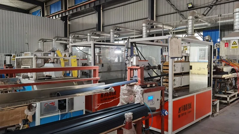
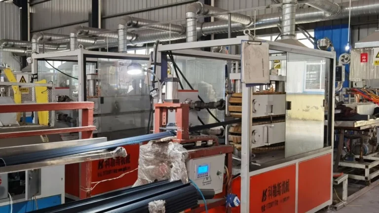
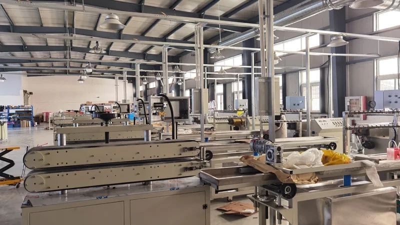
Calibration and downstream hardware matter as much as the extruder itself: sizing sleeves, tanks, haul-off and cutting must be matched to the section. On integrated lines, secondary features such as punched holes or printed markings are added while the profile is still moving, which removes a separate handling step and the tolerance stack that comes with it.
ZetarVac runs 7+ automated extrusion lines with a maximum profile width of 600 mm, and punching, embossing and printing are available as in-line operations. For your project, that means secondary features can be integrated into the run instead of added in a separate pass, reducing handling and tolerance accumulation.
How Do Temperature and Screw Speed Shape the Melt?
Barrel zones heat and homogenize the melt, and the final die head zone sets the temperature at which the profile exits the tooling. Screw speed sets the output rate and adds shear heating of its own. Raise speed without re-balancing the zones, and both melt pressure and viscosity shift, which shows up as dimension drift within minutes.
For orientation, rigid PVC melts toward the lower end of the thermoplastic temperature scale, polyolefins such as HDPE and PP sit higher, and filled or high-heat engineering compounds higher again — always inside the compound supplier’s stated processing window. Pushing rigid PVC past its limit triggers degradation and discoloration long before problems are obvious at the die, and the scrap appears downstream as brittleness. Datasheets list Vicat softening temperature1 as a first indicator of the heat resistance you are working against.
For PVC-U compounds, ISO 11632 designates and specifies the unplasticized PVC extrusion material itself, covering both designation and specification. That matters at the procurement stage because the parameter window you run should trace back to the compound class named on the drawing, not to a generic resin number. If a quote cannot name the compound class, the parameter discussion has no anchor.
"Raising melt temperature always improves surface finish and lets the line run faster."False
Higher temperature lowers viscosity, but past the processing window it drives degradation, discoloration and loss of mechanical properties. For rigid PVC the result is surface bloom and brittle scrap instead of a better product.
"Zone temperatures should be balanced so the melt exits the die head inside the compound's window."True
Balanced zones hold viscosity stable, and stable viscosity is what actually produces gloss and consistent dimensions. Speed increases then come from screw rpm with compensating zone adjustments, never from temperature alone.
In practice, experienced operators change screw speed in small steps and re-measure dimensions before the next adjustment, because the melt needs a few minutes to reach a new equilibrium. Independent references such as the SPE Extrusion Division publish extensive troubleshooting material on balancing output, pressure and melt quality across this process.
Why Does Vacuum Calibration Decide Final Dimensions?
The melt leaves the extrusion die larger and softer than the finished section, so final geometry is fixed downstream in the vacuum calibration tank. Vacuum pulls the hot profile against a water-cooled sizing sleeve while cooling water solidifies it. If vacuum level, water temperature or sleeve length is wrong, no downstream adjustment recovers the dimensions.
In profile extrusion practice, vacuum is set high enough to hold the hot section against the sleeve wall, and multi-stage tanks lower it stage by stage as the section stiffens. Cooling water is chilled to a level that freezes the outer skin quickly without shocking the melt, and it is held constant because even small shifts move the solidification point. Uneven cooling is the hidden failure mode: a section with thick and thin walls solidifies at different rates, and the resulting differential shrinkage appears as bow, twist or out-of-square geometry that looks like a tolerance problem but is a cooling problem.
Wall transitions deserve attention at the design stage, before the extrusion die is cut. Sharp internal corners and abrupt thickness changes concentrate stress and slow the cooling of the thick zone, so sections designed with generous radii and gradual transitions calibrate faster and hold tolerance more reliably. For a detailed treatment of tank and sleeve design, see our guide to the vacuum calibration tank in plastic profile extrusion.
"Vacuum and water temperature are set at start-up and stay fixed through the whole run."False
Melt temperature and cooling water drift over hours, and drift moves the solidification point inside the sleeve. Left uncorrected, dimensions walk out of tolerance even though no setting was touched.
"Calibration settings need periodic verification against measured dimensions during production."True
Checking vacuum, water temperature and sample dimensions every hour or two catches drift while correction is still cheap. Operators who log the settings together can link cause and effect quickly instead of guessing.
One practical start-up test: measure the profile immediately after the tank and again once it reaches ambient temperature. The dimensional change between the two points tells you how much residual shrinkage the cooling regime leaves, and that number predicts how the section will behave in service.
Haul-Off Speed and Wall Thickness Control
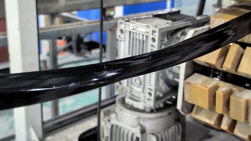
The haul-off3 is the belt or caterpillar unit that pulls the profile away from the die at constant speed, and it is where wall thickness is actually made. Wall thickness follows the ratio of melt output to haul-off speed: increase output at constant speed and walls thicken, increase speed at constant output and they thin. The two must be moved together, within roughly one percent, or the profile will show taper and length variation.
Grip is the second concern. Belt pressure must be high enough to prevent slippage yet low enough to avoid marking soft surfaces or deforming thin walls; dual-belt designs spread the load and suit fragile or high-gloss sections. At start-up, haul-off and cutter must accelerate in synchronization with the extruder, or the first meters of every run will be off-spec. During production, a slipping haul-off announces itself as periodic wall variation, and it should be suspected whenever the variation repeats at a fixed interval along the length.
Cut length accuracy depends on the same synchronization, because the cutter must track the profile speed at the moment of the cut. Length errors that grow over a shift usually point to haul-off slip rather than to the saw.
Co-Extrusion: Running Two Melts Through One Die Head
In co-extrusion, two or three extruders feed separate melt streams into a single die head, where the layers converge and exit as one bonded profile. The interface is the critical zone: the two melts need compatible viscosity and temperature at the meeting point, or layers will wander, thin out or delaminate downstream. Layer ratio is controlled by the relative speeds of the extruders, so every variable from the single-material case exists twice and interacts.
Rigid-flexible combinations are the most common industrial use: a hard body for structure with a soft lip for sealing, guidance or contact. A PP+TPV automotive seat slide rail strip, for example, combines dust exclusion, guiding, wear resistance and low friction with structural support and a flexible sealing lip, all in one continuous extruded profile. An ABS+TPU squeegee strip for household robot vacuums uses ABS for rigid support and TPU for the flexible, wear-resistant wiping edge. Combinations such as PVC+TPU, PP+TPE and TPV+CPVC follow the same logic.
Co-extrusion raises the verification bar as well. Each layer’s thickness and the bond quality need checking, not only the overall cross-section, and a bond that passes visual inspection can still fail a peel check. Agree on which layers carry functional requirements before tooling is designed, because layer placement options narrow quickly once the die head exists.
ZetarVac runs single, double and triple layer co-extrusion with combinations actually in production, including PP+TPV, PP+TPE, PVC+TPU, ABS+TPU and TPV+CPVC. If your section needs a rigid body with a soft sealing or contact lip, that is a proven configuration rather than an experiment.
What Should You Verify Before Approving First Article?
Approve a first article against measured dimensions on the actual cross-section, not a visual check. Measure overall width and height, wall thicknesses and critical functional features at several points along the profile. Material properties are confirmed with standardized tests, and tensile testing to ASTM D6384 is the default citation for extruded profiles.
For window and door profiles, EN 126085 specifies PVC-U profile geometry, impact resistance and heat reversion, so parameter verification should be mapped to the clauses the product claims compliance with. Outdoor profiles additionally face weathering evaluation under laboratory light exposure per ISO 4892, which is a material and process question as much as a specification question. Asking which clauses a supplier tests in-house, and which are sent out, tells you how mature the quality loop really is.
"Once the first article passes, the process is proven stable for volume production."False
A first article is a single point in time, usually taken after careful manual tuning. Tooling wear, material lot changes and temperature drift all appear after hours of running, not minutes.
"Stability is demonstrated with dimensional data collected across a continuous production run."True
Repeat measurements at fixed intervals over several hours show whether the process holds tolerance on its own or only with constant correction. That capability data is exactly what a structured supplier review should request.
When reviewing capability data, ask for the raw measurement log rather than a summary alone. The sampling interval, sample size and the settings recorded alongside each measurement determine whether the data can actually support the tolerance you need on your section.
ZetarVac holds a minimum achievable dimensional tolerance of ±0.05 mm on the profile cross-section, subject to material and section geometry, and supports prototyping, small batch and large batch production with reference monthly capacity of about 300–500 tonnes across the extrusion lines. Tight tolerances are therefore practical to discuss early, while the section can still be adjusted for manufacturability.
You can compare equipment, tolerance and process capability in detail in our custom plastic profile extrusion manufacturer capabilities overview before submitting drawings.
FAQ
How long does it take to stabilize parameters after a die change?
Expect one to three hours on a familiar section and longer on a new cross-section. The line must reach thermal equilibrium, and vacuum, haul-off and cutting have to be re-synchronized. Complex multi-wall sections can take a full shift before capability data is meaningful.
Which parameter should I adjust first when dimensions start drifting?
Check haul-off speed and melt temperature first, because they are the most common sources of drift. Confirm cooling water temperature is constant before touching vacuum settings. Change one variable at a time and re-measure before the next adjustment.
Can every feature of a complex profile be held to the same tolerance?
No. Tight tolerances are realistic on features set directly by the calibration tool and less realistic on free-cooling surfaces or thin flexible lips. Identify the functional features early so the section can be designed around them.
How does changing material affect the parameter set?
Every compound brings its own melt temperature window, shrinkage and cooling behavior, so a material change is a new process setup rather than a minor edit. Even a regrind ratio shift or a color change can move dimensions enough to require re-tuning.
If you are comparing process windows or evaluating suppliers for a current project, share your drawings and target tolerances with ZetarVac through our China plastic extrusion manufacturer page, or talk to an engineer about your application. Reviewing your cross-section against available die and calibration capability early is the most reliable way to catch manufacturability issues before tooling starts.
-
ISO 306: ISO 306 defines the Vicat softening temperature test, a common indicator of thermoplastic heat and creep resistance. ↩
-
ISO 1163: ISO 1163 specifies unplasticized PVC (PVC-U) moulding and extrusion materials, covering their designation and specification. ↩
-
Haul-off: The haul-off is the belt or caterpillar unit that pulls the extruded profile away from the die at a constant, controlled speed. ↩
-
ASTM D638: ASTM D638 is the standard tensile test for plastics and the default citation for verifying mechanical properties of extruded profiles. ↩
-
EN 12608: EN 12608 specifies PVC-U profiles for windows and doors, covering profile geometry, impact resistance and heat reversion. ↩