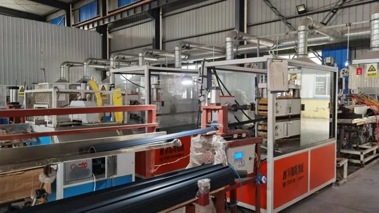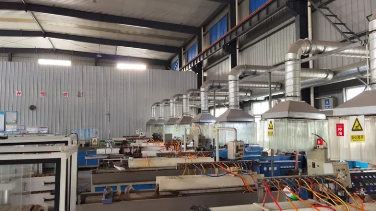
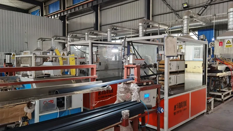
Every cross-section drawing that reaches an extrusion supplier gets the same first question from the die designer: how much area reduction will this section need, and can the line handle it? That question is the extrusion ratio in practical clothing. The term is used loosely in buyer-supplier conversations, yet it sits behind die pressure, melt temperature, weld-line strength, warp and, ultimately, the tolerance you can hold in volume production. This article defines it precisely, separates it from the screw and haul-off numbers it is often confused with, and explains how to evaluate and verify it while you are comparing suppliers.
- Extrusion ratio is the cross-sectional area entering the die divided by the cross-sectional area of the product leaving it, and it measures how hard the melt is worked.
- For rigid thermoplastic profiles the practical window is narrow, and it depends on material, section geometry and line layout rather than on preference.
- Extrusion ratio, screw compression ratio and draw-down ratio describe three different points on the line and should never be used interchangeably.
- Too low a ratio leaves weak weld lines and drifting dimensions; too high a ratio brings die pressure, melt fracture and bow from uneven orientation.
- The ratio is verified on the running line by measuring the stabilized cross-section, not from the part drawing alone.
- Material rheology sets the ceiling: rigid PVC, polyolefins and engineering grades tolerate different amounts of area reduction.
What Is Extrusion Ratio?
Extrusion ratio is the ratio between the cross-sectional area of the material entering the die and the cross-sectional area of the product leaving it. Written as a formula, R = A₀ ÷ A_f, where A₀ is the inlet (billet or die-entry) area and A_f is the finished cross-section. It expresses how severely the material is deformed and worked as it passes through the die head.
The concept is easiest to see in metal extrusion, where billets are pushed through dies at ratios of tens or even hundreds to one and the metal solidifies after the exit. Molten polymers behave differently. A thermoplastic melt is far more viscous and it is pulled, not only pushed, through calibration. In profile extrusion the die therefore works with a modest area reduction, and the rest of the dimensional change happens as draw-down between the die exit and the haul-off1. The melt also swells as it leaves the die2, so the designer targets an oversized opening and lets draw-down bring the extruded profile to size.
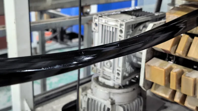
Profile extrusion is one branch of plastics extrusion as a whole; the broader process landscape is summarized in ZetarVac’s plastic extrusion molding overview.
For a hollow or multi-web section, the ratio calculation is not just outer dimensions. The designer works from true cross-sectional areas, counting webs, hollows and wall transitions, because pressure drops across the die head scale with the real flow geometry rather than with the bounding rectangle. That is why two profiles with identical outer dimensions can demand completely different die designs.
Why Does the Extrusion Ratio Matter for Profile Quality?
Because the ratio sets how much mechanical work and pressure the melt receives inside the die. Too little deformation and the material leaves the die under-consolidated; too much and pressure plus temperature climb until surface and dimensional defects appear. It is one of the few process choices that affects strength and shape at the same time.
At the low end, the streams that split around webs and hollows recombine under insufficient pressure, leaving weak knit lines that can crack in service. Surfaces may look matte or show flow marks because the melt was not properly homogenized. At the high end, die pressure and shear heating rise sharply: surfaces show melt fracture3, heat-sensitive materials such as rigid PVC begin to degrade, and high frozen-in orientation makes nominally straight profiles bow or twist as different zones shrink at different rates.
When you need to quantify these effects rather than argue about them, ASTM D638 specifies the tensile test method for plastics and is the default reference for comparing strength and elongation between samples cut from different trial runs of the same profile4. Cut specimens from a stable mid-run section of the extruded profile, not from the ends, and keep conditioning identical between runs.
"A higher extrusion ratio always produces a stronger extruded profile."False
Once a rigid section is pushed past the material’s window, extra area reduction mostly buys higher die pressure and melt temperature, not more strength. Orientation increases, so shrinkage becomes directional and a nominally straight profile bows after cooling, which is a dimensional failure even if the tensile number looks good.
"The useful ratio window is set by the material and the section, not by preference."True
Rigid PVC has a narrower window than polyolefins because it degrades at lower melt temperatures. Thin-wall and multi-cavity sections need gentler reduction so that every cavity and web fills at balanced pressure rather than one region starving another.
The practical consequence for buyers is that a supplier who quotes an aggressive ratio without explaining the material window is guessing. Ask which melt temperature and die-head pressure the section was trialed at, and what changed between the first and second die correction.
Is Extrusion Ratio the Same as Compression Ratio or Draw-Down Ratio?
No. The three numbers describe different points on the line — inside the screw, at the die, and after the haul-off — and each controls a different failure mode. Using them interchangeably in a specification is a common way for both sides to assume the other has verified the process.
The screw compression ratio5 is built into the screw geometry: feed-channel depth versus metering-channel depth. It governs melting rate and homogeneity before the melt ever reaches the die. The extrusion ratio is a die-side number. The draw-down ratio is a line-side number, defined by die exit dimensions versus final product size, and it is what actually fixes your final dimensions together with the calibrator. A useful comparison:
| Indicator | Where it is defined | How the value is set | What it mainly controls |
|---|---|---|---|
| Extrusion ratio | Die inlet area vs product cross-section | From the section geometry and the material’s rheology window | Melt work, die pressure, consolidation |
| Screw compression ratio | Feed vs metering channel depth in the screw | By screw design, matched to the material family | Melting rate and homogeneity |
| Draw-down ratio | Die exit dimensions vs final product size | Small for solid profiles, larger for thin tubing | Final dimensions, orientation, surface |
These are engineering conventions, not guarantees; the right value for your section depends on the material grade, the machine and the calibration design. The same caution applies to thermal headroom: a Vicat softening point measured per ISO 306 tells you how much margin the material has before the chosen ratio pushes melt temperature into the degradation zone6.
"Extrusion ratio and screw compression ratio are interchangeable terms."False
One describes area reduction at the die, the other channel depths inside the screw. Quoting the wrong number in a specification lets each party believe deformation has been verified, and nobody measures the actual die area reduction before tooling is cut.
"Each ratio should be stated separately, with the measurement point defined."True
Name what is measured where: inlet and product cross-section for the extrusion ratio, the screw drawing for compression ratio, calibrator exit dimensions for final size. That vocabulary makes die reviews and first-article reports comparable across suppliers.
What Happens When the Ratio Is Too High or Too Low?
The line tells you quickly. Too high, and die pressure and melt temperature climb, surfaces show melt fracture or gloss variation, profiles twist or bow as oriented melt shrinks unevenly, and heat-sensitive compounds discolor. Too low, and the melt leaves the die under-worked: weld lines over webs become the weak point, surfaces look dull, and dimensions drift because the melt has little pressure memory to hold it against calibration.
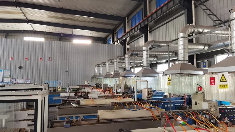
A practical verification checklist for a trial run looks like this: record die-head pressure and melt temperature at stable speed; inspect the surface for sharkskin and gloss bands; cut the profile and check wall distribution across webs; measure the cross-section after the calibrator and again after the profile has fully cooled and rested; and check straightness against the tolerance band at production speed. Most of these symptoms map to specific corrections, and ZetarVac covers the wider catalogue in its guide to common extrusion defects and troubleshooting.
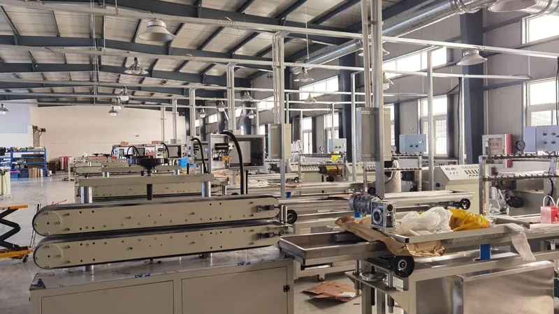
Note that ratio problems often disguise themselves as calibration problems. If wall distribution is lopsided, the first move is usually a core-rod adjustment or a flow-balance change at the extrusion die, not a calibrator fix. Chasing a flow imbalance downstream of the die wastes correction rounds and delays approval.
How Do You Choose and Verify the Right Ratio?
At the design stage the die designer computes area reduction from the true section geometry and the material’s rheology, then sets the inlet area and the expected draw-down. Standards constrain the result on the product side: EN 12608 specifies the profile geometry, impact resistance and heat reversion requirements for PVC-U window and door profiles, so a section designed to that standard has to reach its verified properties inside whatever ratio window the die allows. Similar logic applies to automotive and industrial profiles sold against their own specifications.
Co-extrusion adds a second dimension. Each layer has its own flow path through the die head, so the hard and soft materials must arrive at the shared cross-section at balanced pressure and output; the layer-by-layer considerations are laid out in ZetarVac’s co-extrusion die head overview. ZetarVac runs co-extrusion up to three layers, including combinations such as PP with TPV, ABS with TPU and PVC with TPU. The ratio conversation becomes a per-layer conversation, which is exactly why co-extruded sections deserve a longer die-engineering review than single-material ones.
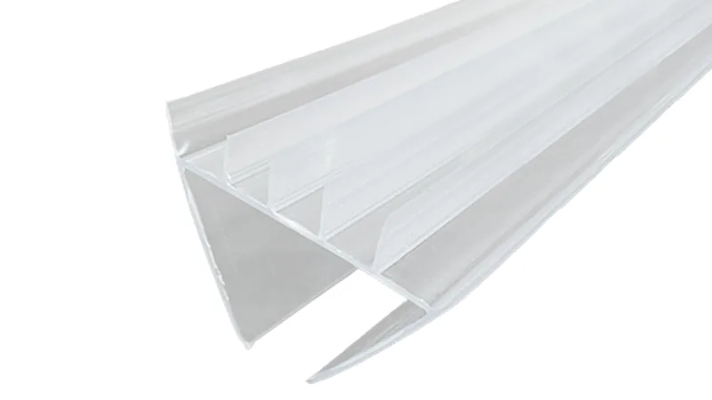
ZetarVac extrudes profiles from 5 to 600 mm wide on more than seven automated lines, including single, double and triple-layer co-extrusion. A range that wide means the ratio window can be tuned to the section on a line that suits it, instead of forcing every profile through one preferred operating point.
Verification belongs on the running line. Approve the process only after the stabilized cross-section has been measured against the tolerance band at production speed, because parts cut immediately after start-up do not represent the following hours.
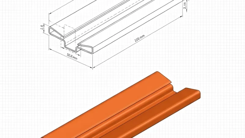
"You can confirm the extrusion ratio from the part drawing alone."False
The drawing fixes the product cross-section, but the inlet area depends on die design, flow geometry and how much draw-down the line applies. Two competent suppliers can legitimately run very different ratios on the same drawing and both make good parts.
"The ratio is verified on the running line, not on paper."True
Measure the actual cross-section after the calibrator and again after the profile has cooled and rested, then compare against the tolerance band. Repeat at production speed, because a process that only passes at slow trial speed is not a production process.
Keep this in mind when you schedule first-article approval. Budget for at least one die correction round on a new section, treat the second run as the meaningful measurement point, and record the process values from that run as the reference for future batches.
On the profile cross-section, ZetarVac works to a minimum dimensional tolerance of ±0.05 mm, subject to material and section geometry. Commitments at that level are only realistic when the extrusion ratio, calibration and haul-off are stable enough to deliver the same cross-section hour after hour, not just during a demonstration run.
FAQ
Does a higher extrusion ratio improve mechanical properties?
Only up to a point. Moderate area reduction improves consolidation and can raise strength, but beyond the material’s window it mainly adds die pressure, orientation and warp. Compare tensile samples from trial runs before accepting that more reduction helped.
Can I specify the extrusion ratio on my drawing?
You can state the product cross-section, material grade and tolerances, but fixing the ratio itself over-constrains the die designer. Treat it as a process parameter the supplier verifies on the line, and review it together during first-article approval.
How does co-extrusion change the extrusion ratio discussion?
Each layer has its own flow path, so the die head must balance pressure and output for every material at the shared cross-section. Hard-soft combinations such as PP with TPV or ABS with TPU need per-layer flow control, which is why co-extruded sections take more die engineering than single-material parts.
What information should I send the supplier for ratio planning?
Send the full cross-section with dimensions and tolerances, the material grade or target properties, wall thickness ranges and the service environment. With that, the die designer can choose an inlet area and draw-down that keep the process inside the material’s window.
How is the extrusion ratio checked before volume production?
By measurement on the running line: cross-section dimensions after the calibration table and again after full cooling and rest, plus surface, wall-distribution and straightness checks at production speed. Record those values so later batches have a reference to compare against.
If you are evaluating suppliers for a custom extruded profile, share your drawings with ZetarVac and talk to an engineer about die design and the process window before tooling is cut — you can start that technical review through ZetarVac’s plastic extrusion manufacturing page or review the full service scope.
-
Draw-down ratio: The ratio between the die exit cross-section and the final product cross-section after the haul-off; it fixes final dimensions together with the calibrator. ↩
-
Die swell: The elastic expansion of a polymer melt as it exits the die, causing the extrudate to leave larger than the die opening. ↩
-
Melt fracture: A surface defect caused by unstable melt flow at high shear stress, appearing as sharkskin, matte bands or distortion. ↩
-
ASTM D638: The standard test method for tensile properties of plastics, used to compare strength and elongation between extrusion trial runs. ↩
-
Screw compression ratio: The ratio of feed-channel depth to metering-channel depth in the extruder screw, governing melting rate and homogeneity. ↩
-
Vicat softening temperature: The temperature at which a loaded needle penetrates a plastic specimen by 1 mm per ISO 306, indicating heat-resistance headroom. ↩