Heavy gauge thermoforming turns thick thermoplastic sheet into rigid, functional parts — equipment housings, machine guards, industrial trays and structural components — by heating the sheet, drawing it over a mold with vacuum, then cooling and trimming the result. It is the standard route when you need a strong, large part without committing to expensive high-pressure tooling, and it is the process behind most of the big plastic covers you see on factory floors, medical carts and outdoor kiosks.
This guide walks through the heavy gauge thermoforming process step by step: what happens at each stage, which parameters matter, the failure modes to watch, and the checks that separate a stable production part from a lucky first article. For a wider view of forming methods and materials before going deeper, the vacuum forming process overview is the natural starting point.
- Heavy gauge thermoforming heats thermoplastic sheet from 0.5 mm to 15 mm thick, forms it over a mold with vacuum, then cools and trims it into a rigid part.
- The core steps are sheet selection, clamping, heating, forming, cooling, trimming and inspection, and each step has its own parameters and failure modes.
- Deep draws thin the sheet unevenly; corners and steep sidewalls can lose 30–50% of nominal thickness unless the design and tool compensate.
- Material choice drives heating time, formability, heat resistance and flame rating — ABS and HDPE dominate industrial work, PC and PMMA cover clarity and impact.
- Five-axis CNC trimming converts a formed shell into a finished part with accurate holes, slots and edges referenced to the formed geometry.
- First-article approval proves geometry, not process stability, so tolerance and inspection planning should cover the whole production run.
What Is the Heavy Gauge Thermoforming Process?
Heavy gauge thermoforming is a process that heats a thermoplastic sheet until it softens, stretches it over a mold using vacuum pressure, then cools and trims it into a rigid finished part. It handles sheet from 0.5 mm to 15 mm thick and produces strong parts such as equipment housings, machine covers, industrial trays and structural components.
The term heavy gauge describes the sheet, not the machine. Thin-gauge forming runs web-thin, roll-fed material at high speed for packaging; heavy gauge work uses cut sheet formed one part at a time or in low-count multiples. That single difference changes everything downstream: heating takes minutes instead of seconds, forming forces are higher, cooling becomes a deliberate engineering step, and trimming is a machining operation rather than a die cut.
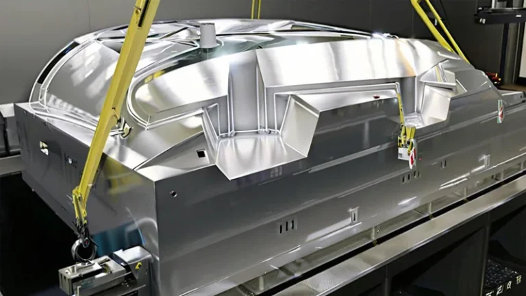
The second difference is scale. Forming platforms routinely handle lengths up to about 2,500 mm, which is why the process dominates applications where injection tooling would be prohibitively expensive or the part simply too large — machine shrouds, medical device housings, kiosk bezels, vehicle panels and material-handling trays. You can see how a supplier structures this work on the heavy gauge thermoforming service page. For buyers, the practical consequence is simple: heavy gauge thermoforming competes on tooling cost and part size, not on cycle time.
Steps 1–3: Sheet Selection, Clamping and Heating
Everything that goes wrong later can usually be traced to decisions made before heat is applied, so the first three steps deserve more attention than they usually get.
Material and gauge selection comes first, driven by service conditions rather than price alone: impact exposure, operating temperature, UV, clarity and any flame requirement. Gauge follows from stiffness and draw depth. Thicker sheet adds rigidity but lengthens heating, slows cooling and worsens thinning in deep draws, so the correct answer is rarely the thickest sheet that fits.
Clamping holds the sheet in a frame with consistent tension. Uneven clamping skews the draw, wrinkles the sheet in female tools and shifts thinning patterns between parts, which quietly ruins tolerance control on flat, dimension-critical panels.
Heating is where heavy gauge thermoforming earns or loses its quality reputation. Radiant ceramic heater banks bring the sheet to its forming window, and thick sheet is typically heated from both sides because conduction through several millimetres of polymer is slow. Typical sheet temperatures sit in the 130–170 °C range for ABS and around 170–200 °C for PC, though exact setpoints depend on grade, gauge and machine. Operators judge readiness by sag: too little heat leaves poor detail and high residual stress, too much causes surface marks, degradation and uneven thinning.
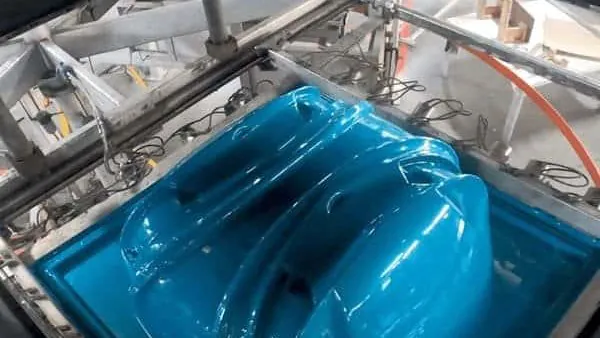
Sheet gauge from 0.5 mm to 15 mm with forming lengths up to about 2,500 mm means one process can cover a thin equipment liner and a full-size machine shroud alike. For a mixed product range, that usually means one supplier and one tooling approach can serve both small covers and large enclosures, which simplifies sourcing and qualification.
Step 4: How Does Vacuum Forming Pull the Sheet Into Shape?
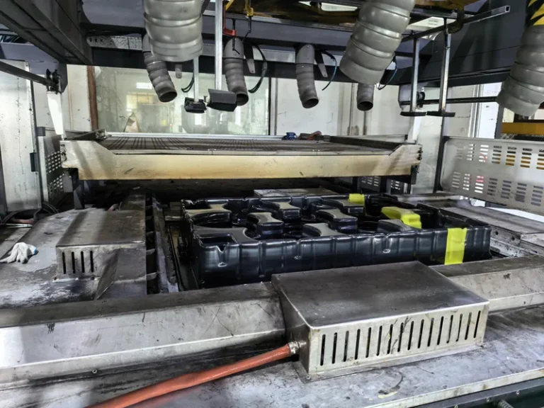
The softened sheet is drawn against the mold surface by evacuating the air trapped between sheet and tool, and atmospheric pressure does the actual forming work. A vacuum of roughly −0.08 to −0.095 MPa — most of a full atmosphere — presses the sheet onto every detail of the tool within seconds.
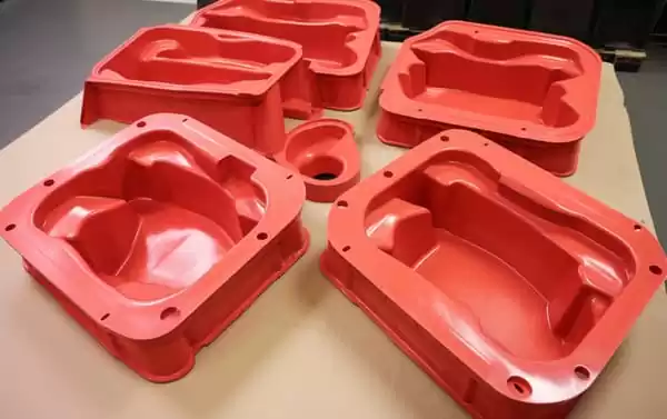
Tool choice shapes the part before vacuum is even applied. A male tool forms the inside of the part and naturally controls internal dimensions, while a female tool forms the outside and gives better surface detail on the visible face. For deep or complex draws, the sheet is pre-stretched — billowed upward with a vacuum bubble or pushed with a plug assist — before final forming, which distributes material and cuts corner thinning dramatically.
Where sharper detail or texture is needed on a visible surface, pressure forming adds compressed air above the sheet to press it harder into the tool than vacuum alone can. It shares every other step with vacuum forming but commands higher tooling cost, so it earns its place on customer-facing parts. For an independent primer on these variants, the IQS Directory’s thermoforming guide covers the process family in plain terms.
"A uniform starting sheet thickness means the finished part has uniform wall thickness everywhere."False
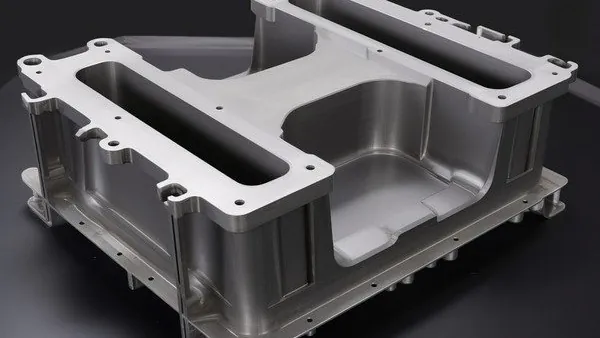
Vacuum forming stretches the sheet over the tool, and the stretch is never even. Corners and steep sidewalls thin the most, so deep-draw features can lose a third or more of nominal gauge. Ignoring the variation leaves weak points exactly where parts get handled and fastened.
"Wall thinning is predictable, so the design should be built around it."True
Experienced formers measure the thickness distribution on trial parts and adjust radii, draft angles and draw ratio accordingly. Where a feature must keep its gauge, plug assist, pre-stretch or a revised tool position moves material to where it is needed.
Steps 5–6: Cooling, Demolding and Five-Axis Trimming
Cooling is not idle time — it is the step that locks in the geometry. The mold and the part are cooled with fans or chilled tool surfaces until the sheet drops well below its deflection temperature; release too early and the part keeps shrinking and warping on the rack. Large flat panels are often held in cooling fixtures because free cooling lets them bow. Uneven cooling between the two faces of a part is the classic cause of distortion, so air flow and tool temperature get engineered, not improvised.
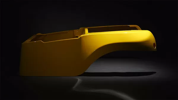
A formed shell is still an oversized blank with web edges. This is where five-axis CNC trimming turns it into a part: the trim head follows the formed surface, cutting outlines, holes, slots and clips in one setup. Because the trimmed outline follows the forming tool, edges and holes stay referenced to the formed geometry rather than to a manual layout line, which is what lets mating housing halves line up in assembly run after run. Post-forming details such as hardware inserts, welded bosses or gasket seats are added at this stage.
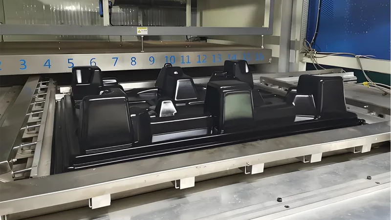
Formed parts are finished on a five-axis CNC trimming centre, so the trimmed outline follows the forming tool instead of a manual layout. For your project, that means hole patterns and edges stay aligned to the formed surfaces across the run — the difference between an enclosure that assembles cleanly and one that needs hand fitting.
Which Materials Work Best for Heavy Gauge Thermoforming?
ABS, HDPE, PP, PC and PC/ABS cover most heavy gauge thermoforming work. ABS is the default for housings, cases and guards; HDPE for industrial trays and liners; PP for trays, boxes and packaging; PC and PMMA where clarity or impact resistance matters. Soft grades — TPE, TPU and TPV — cover liners, seals and flexible protection parts that rigid sheet cannot provide.
| Material | Typical heavy gauge applications | Selection notes |
|---|---|---|
| ABS | Equipment housings, cases, guards | The industrial default; forms predictably and finishes well |
| PC | Clear guards, protection covers, automotive parts | High impact; needs higher forming temperatures and dry sheet |
| PC/ABS | Automotive interiors, equipment housings, guards | Blends PC toughness with ABS formability |
| HDPE | Industrial trays, equipment liners, storage boxes | Strong chemical resistance; watch warpage on flat panels |
| PP | Trays, packaging, boxes, equipment liners | Light and chemical-resistant; handles living hinges |
| PMMA | Clear covers, luminaires, display parts | High clarity and weathering; more brittle than PC |
| ASA | Outdoor equipment housings, automotive exterior parts | UV-stable surface for parts that live outside |
| PA6 / PA66 | Special industrial structural parts | Selected when stiffness and heat resistance outrank formability |
When a housing sits near motors, drives or outdoor heat, compare candidate grades by heat deflection temperature rather than by generic data sheet numbers: ISO 75-2 specifies the test that measures the deflection temperature of plastics under flexural load, and it is the ranking that tells you how far a formed panel can be pushed in service before it softens.1 Glass-filled PP and PA grades extend stiffness for structural parts, while POM serves small precision features where low friction matters.
What Tolerances and Quality Checks Should You Expect?
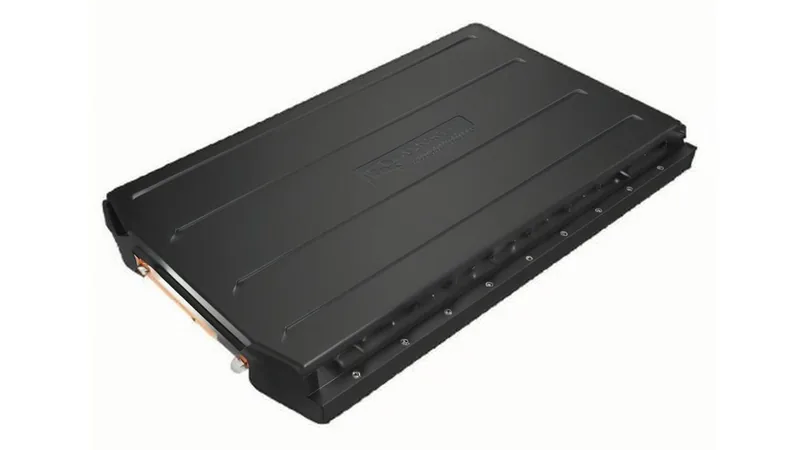
Formed dimensions are typically held to about ±0.5–1.0 mm on modest features, while five-axis trimmed edges, holes and slots hold much tighter limits because they are machined after forming. Formed surfaces depend on material, draw depth and tool quality, so tolerance review belongs in the drawing stage, not after tooling is cut.
Treat formed and trimmed features differently in your drawing. Formed wall positions, outside radii and overall shell dimensions carry the process’s natural variation and should get workable tolerances; machined features can be tight because the trim is indexed off the formed part. Draft angles, generous radii and realistic shrink allowances do more for fit than any amount of tolerance tightening. These choices are the core of a forming-specific design review, and the DFM checklist for thermoformed parts and molds walks through them in checklist form.
Mechanical validation follows the same logic. ASTM D638 specifies the tensile test used to verify both incoming thermoforming sheet and finished formed parts, so it constrains the strength values a supplier can legitimately quote against a material certification.2 For electrical equipment, UL 94 defines the flammability classifications that many equipment builders require before a formed enclosure can be fitted to their product.3 And where a formed cover is sold as dust-tight or splash-proof, IEC 60529 defines the IP code that grades the degrees of protection an enclosure actually provides.4
"Once the first article passes inspection, the rest of the run will match it."False
First-article approval confirms geometry at one point in time. Sheet lots, heater aging and ambient conditions drift during a production run, and formed surfaces move with them. Without in-run checks, a signed-off first article says nothing reliable about piece 500.
"Process stability needs monitoring across the run, not just at approval."True
A capable supplier checks formed and trimmed dimensions at planned intervals, measures wall thickness at known thin spots and records the results. That history is what lets tolerance claims be defended when a customer audits the parts.
Practical inspection planning is straightforward: agree on the gauge plan and sampling frequency at quoting stage, check thickness at the corners where thinning peaks, and use CMM or fixture checks on trimmed hole patterns that mate to other components.
The plant runs more than 20 vacuum forming and thermoforming machines within 45+ total production lines, with reference monthly capacity of roughly 100,000–200,000 pieces, and supports prototyping, small batch and large batch production. For your program, that means the process validated on your prototype does not have to change when volumes grow.
FAQ
How thick can the sheet be for heavy gauge thermoforming?
Heavy gauge thermoforming processes sheet from 0.5 mm to 15 mm thick, with forming lengths up to about 2,500 mm. Most industrial housings and trays land between roughly 2 mm and 8 mm, where rigidity, heating time and draw depth stay in balance.
What does a typical thermoforming cycle look like?
Heating takes the largest share of the cycle — often one to several minutes for thick sheet, depending on material and gauge. Forming itself takes seconds, while cooling and trimming scale with part size and complexity. Project timelines hinge on tooling and validation far more than on the forming cycle.
What is the difference between vacuum forming and pressure forming?
Both are thermoforming. Vacuum forming uses atmospheric pressure alone to press the softened sheet onto the tool, while pressure forming adds compressed air above the sheet for sharper detail and texture. Pressure tooling costs more, so it earns its keep on visible or finely detailed surfaces.
What should I prepare before requesting a quote?
Bring a 3D model and a 2D drawing with tolerances, a target material or the service conditions it must survive, expected volumes and any flame-rating or enclosure requirements. A forming-specific design review before quoting catches most issues; the DFM checklist linked above is a practical place to start.
If you are at the stage of comparing suppliers for a formed enclosure, tray or cover, send your drawings or share your part requirements, and talk to an engineer through ZetarVac’s heavy gauge vacuum forming team. A drawing review before tooling commitment is the cheapest engineering decision you will make on the program.
-
ISO 75-2: Standard specifying the heat deflection temperature of plastics under flexural load, used to rank formed-part service temperature. ↩
-
ASTM D638: Standard test method for tensile properties of plastics, used to validate thermoforming sheet and finished formed parts. ↩
-
UL 94: Standard for the flammability of plastic materials, the basis for flame ratings required on many equipment enclosures. ↩
-
IEC 60529: Standard defining the IP code for degrees of protection provided by enclosures, applied to formed covers and housings. ↩