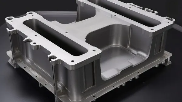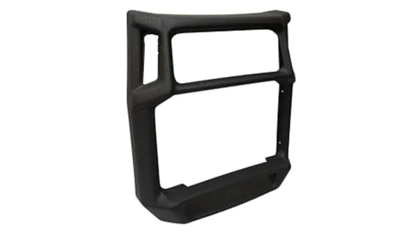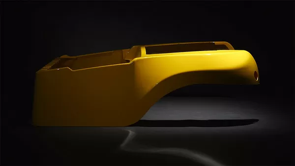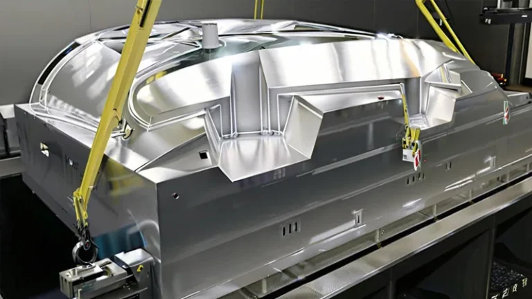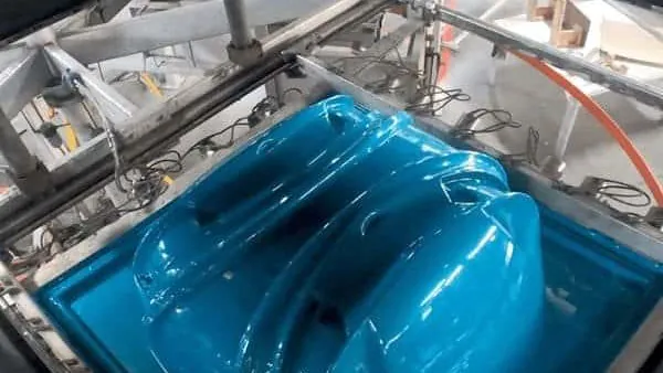
Heavy-gauge thermoforming turns a thick plastic sheet into structural parts — equipment housings, machine covers, trays, and load-bearing components — by heating the sheet, drawing it over a mold with vacuum, and trimming the result to final shape. Because the process looks deceptively simple, design reviews often skip the checks that make forming predictable. This checklist walks through the decisions that matter before mold release: draw envelope, tool architecture, process windows, tolerance strategy, and supplier readiness — the same fundamentals outlined in the vacuum forming process hub.
- Freeze part geometry, draw depth, and corner radii before mold design starts, because late geometry changes force tool rework.
- Treat the mold as an airflow system: vent count, vent placement, and vacuum path control wall distribution more than heater settings do.
- Define wall-thickness targets by zone instead of one number for the whole part, and verify them with a cut-and-measure plan.
- Separate cosmetic acceptance from functional acceptance, and give every critical dimension a named measurement method.
- Base first-article approval on repeated forming cycles across shifts, not on one good sample.
- Confirm supplier readiness with process evidence and corrective-action loops, not just a finished tool.
What Should a Heavy-Gauge Thermoforming DFM Checklist Verify Before Mold Release?
A pre-release checklist should confirm three things: the geometry is formable within a realistic draw envelope, the mold supports repeatable vacuum and cooling behavior, and every critical feature has an agreed measurement method. If any of the three is still open, machining the tool only locks in the risk. The cheapest correction point in thermoforming is always the CAD file, never the finished mold.
Start with the draw envelope, the ratio of formed surface area to the sheet area that feeds it.1 Shallow panels form almost anywhere; deep cavities concentrate stretch at the base and pile up material at the flange, so wall thickness must be planned zone by zone rather than quoted as a single number. Material validation belongs at the same gate: ASTM D638 specifies the standard tensile test for plastics, and it should be run on samples cut from formed walls — not only on raw sheet — because forming orients the material and shifts its strength and elongation.
Next, review the tool as an airflow system. Every deep pocket, sharp corner, and rib is a place where air can trap and detail can wash out, so vent locations must follow the last-touch map of the sheet, not the drawing margin. If your program sits between gauge ranges, the comparison of heavy and thin gauge thermoforming shows how DFM priorities shift as sheet thickness rises.
"One clean first pull proves the part is production ready."False
A single formed sample validates one sheet lot, one heat profile, and one operator at one moment. Sheet lot changes, heater drift, and vent contamination all move the result later, which is how defects surface after launch instead of during trials.
"Repeatability across shifts is the real first-article gate."True
Three to five consecutive pulls on different shifts that hold wall thickness, flange flatness, and hole positions inside limits say far more than one perfect part. If the spread is stable, the process can be tuned; if not, the geometry or the tool needs work first.
Once those gates are written down, the release review becomes a checklist audit instead of a debate: geometry envelope confirmed, vent map drawn, material data attached, and measurement plan agreed. Anything still open is a known risk with an owner, not a surprise discovered on the first pilot pull.
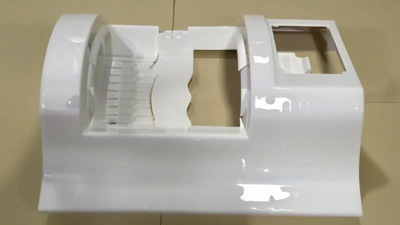
ZetarVac processes sheet from 0.5 to 15 mm thick and forms parts up to about 2,500 mm long, with 5-axis CNC trimming after forming, so deep enclosures and large covers with finished flanges stay inside one process instead of needing a separate machining step.
Which Part Features Drive the Most Thermoforming Risk?
Feature clusters, not single dimensions, cause most first-trial failures. A deep cavity with tight corners and a thin flange interacts badly: each feature amplifies the others, so review the geometry as a system — where the sheet stretches, where it piles up, and where air can hide.
The table below is the working version of that review. Use it in the design review meeting and record a decision for every row before the tool is released for machining.
| Feature | DFM guideline | Typical failure mode |
|---|---|---|
| Draw depth | Keep the first release shallow, or plan plug assist for deep cavities | Base thinning, flange build-up |
| Corner radii | Use generous radii, at least several times the sheet thickness | Stress whitening, thin corners, service cracking |
| Draft angle | Add 2–5° or more on vertical walls, more on textured surfaces | Ejection drag, distortion on demolding |
| Wall transitions | Step or taper gradually between thickness zones | Sink marks, uneven stiffness, warpage |
| Vent placement | Position vents at last-touch areas and deep pockets | Trapped air, lost detail, blisters |
| Flanges and bosses | Support mounting lands and reinforce load paths | Flange waviness, boss collapse, assembly mismatch |
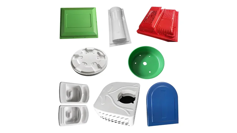
Material choice multiplies or damps every row in this table. ABS remains the workhorse for housings and guards, PC suits clear guards and covers that need impact resistance, and PMMA delivers high-clarity display covers; HDPE, PP, and glass-filled PP grades carry industrial trays and structural parts. Match the grade to the failure mode you most need to avoid, then confirm it with the tensile and deflection data already gathered at the release gate.
How Do You Build a Repeatable Process Window Before Production?
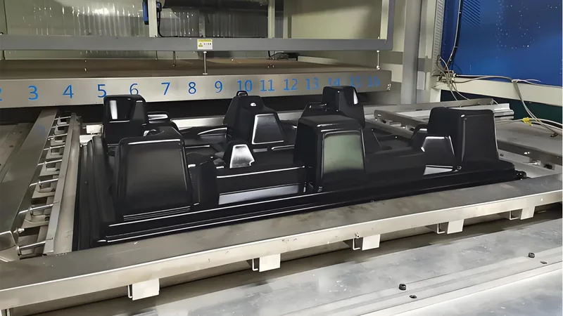
A process window is repeatable only when every setting has a permitted range, a linked defect signal, and a defined action when the limit is exceeded. Write heating, vacuum, and cooling as a recipe with limits, then verify that recipe across at least two sheet lots before the pilot is signed off.
Heating comes first, because heavy sheet stores heat. Thick blanks need heat from both sides and a soak long enough for the core to catch up with the surfaces; the operator watches for even sag across the sheet2 rather than trusting heater readouts alone. For stiffness-critical parts, ISO 75-2 specifies the heat deflection temperature test under flexural load, which sets a practical floor for when a formed part can be handled and how much residual heat it can carry into trimming. Industry references such as the SPE Thermoforming Division publish detailed guidance on heater zoning and sheet temperature control for exactly this stage.
For formed equipment housings, the electrical end-market adds a second material gate: UL 94 defines the flammability classifications that many enclosures must meet, so the selected grade — and the heat history it sees during forming — has to preserve that rating, not just the datasheet value.
Vacuum behavior decides how the softened sheet meets the mold. Heavy-gauge work needs real vacuum volume behind the forming table, so reservoir capacity and valve response matter as much as pump size; a slow pull leaves webbing between features, while an uncontrolled pull freezes thickness variation into the part. Cooling then locks the result: hold mold temperature steady and dwell long enough for the part to stiffen below its deflection range, or warpage and springback will appear after the part leaves the mold.
"Higher heater settings fix forming defects in thick sheet."False
Extra heat softens the blank but also increases sag, deepens surface marking, and raises residual stress after cooling. Without matching changes to vacuum timing and cooling, visible defects are simply traded for hidden distortion.
"Balanced heat plus controlled cooling stabilizes the process."True
Tune the heater zones until the sheet reaches forming temperature evenly, then hold mold temperature and dwell until the part is stiff below its heat deflection range.[^hdt] That combination addresses immediate defects and post-cooling warpage together.
Trimming is the last window worth defining early. Formed outlines that follow the forming tool machine predictably; free-form trim lines add setup variation. Agree trim order, support points, and clamp strategy before the first pilot batch, and record them as part of the recipe rather than leaving them to the operator on the day.
How Should Tolerances and Inspection Be Planned for Formed Parts?
Plan tolerances around the physics of forming: wall thickness varies with draw, so formed surfaces get functional bands, while hole positions and mounting faces get tight tolerances tied to datums. Every critical dimension needs one measurement method and one named owner before pilot parts exist.
Put the datum structure in GD&T so that design, forming, and trimming measure the same features the same way.3 Then split the sampling plan by consequence: full measurement of critical dimensions on first-article parts, per-lot sampling under a defined AQL framework for released production,4 and trend monitoring on wall thickness using a cut-and-measure plan at fixed locations on the part.
"Tolerances can be copied from an injection molding drawing."False
Formed walls vary with stretch direction and draw depth, so blanket injection-grade tolerances fail on paper. Give tight tolerances only to machined features and datum surfaces, and let formed surfaces carry realistic functional bands.
"Machined trimming features carry the tight tolerances."True
Hole positions, mounting faces, and flange edges are defined by trimming after forming, so they can hold tolerances like any machined part. Formed walls and curves should carry wider functional bands agreed during DFM.
Cosmetic and functional acceptance should also be separated in writing. A visible sink mark on a non-functional surface may be acceptable at one level and unacceptable on a display cover; a boss out of position is a functional failure at any level. Write both definitions into the acceptance document so pilot decisions stay mechanical.
For context on where these parts end up, the overview of heavy-gauge thermoformed applications covers housings, trays, and structural uses across industries.
When Is a Mold Supplier Ready for Pilot Production?
A supplier is ready when the process, not just the tool, is proven: stable cycles across shifts, documented settings, and a corrective-action loop with owners and dates. A physically finished mold is a prerequisite, never the endpoint of readiness.
Confirm readiness across four areas: process evidence (setpoint logs and cycle data from repeated pulls), tooling integrity (vent cleaning intervals tied to lot size, ejection and clamp condition), QA governance (acceptance limits written down, corrective actions logged with owners), and change control (every setting change produces a revision record before the next run). A supplier who can show all four will absorb normal production noise; one who cannot will convert every disturbance into a schedule slip.
ZetarVac forms ABS, PC, PC/ABS, ASA, HDPE, PP, PP/GF, PMMA, and other engineering grades for automotive, industrial, medical, agricultural, and logistics applications, so material selection can be validated against a working grade library instead of datasheet optimism.
Capacity also belongs in the readiness conversation, because pilot decisions are easier when the same supplier can scale. ZetarVac runs more than 20 vacuum forming machines among about 45 production lines, with reference monthly capacity of 100,000–200,000 pieces, and supports prototyping, small batch, and large batch production, so a program can move from first trials into volume without requalifying a new partner.
FAQ: Heavy-Gauge Thermoforming DFM
How thick can a heavy-gauge thermoformed wall be?
Industrial heavy-gauge lines typically process sheet from about 0.5 to 15 mm. ZetarVac works across that full range and forms parts up to roughly 2,500 mm long, which covers most enclosure, cover, and tray programs. Beyond that range, forming windows narrow sharply and the economics change.
Why does wall thickness vary across a formed part?
The sheet stretches where it touches the mold last, so deep draws thin at the base and thicken at the flange. The fix is not a magic setting but a zone plan: expected thickness bands per area, verified by cutting and measuring agreed locations on pilot parts.
What tolerances are realistic on a formed part?
It depends on size, depth, material, and feature type. Formed surfaces carry wider functional bands; trimmed features such as holes and mounting faces hold tighter limits. Agree tolerances per feature during DFM rather than inheriting a generic table.
Can vacuum forming produce clear covers and guards?
Yes. PC and PMMA are standard grades for clear guards, covers, and display parts. For transparent parts, ISO 13468 specifies the total luminous transmittance test, which gives you an objective number for clarity instead of judging samples by eye.
How many pilot runs are enough before release?
There is no fixed number. A sound exit point is when failure types stop changing and critical dimensions hold their capability limits across shifts, sheet lots, and maintenance cycles. If failures keep mutating, the geometry or tool needs review before volume.
To keep working through the checklist, explore the vacuum forming process hub for the underlying forming fundamentals, or see how a China vacuum forming manufacturer runs heavy-gauge programs from prototype through volume production.
-
Draw ratio: the ratio of formed part surface area to the sheet area feeding it, used to estimate how far the sheet must stretch during forming. ↩
-
Sag: the downward droop of a heated sheet before forming, used as a visual indicator that the sheet has reached forming temperature. ↩
-
GD&T: Geometric Dimensioning and Tolerancing, a standardized system for defining engineering tolerances through datums and tolerance zones. ↩
-
AQL: Acceptable Quality Level, the sampling basis that defines the acceptable defect concentration for an inspected lot. ↩