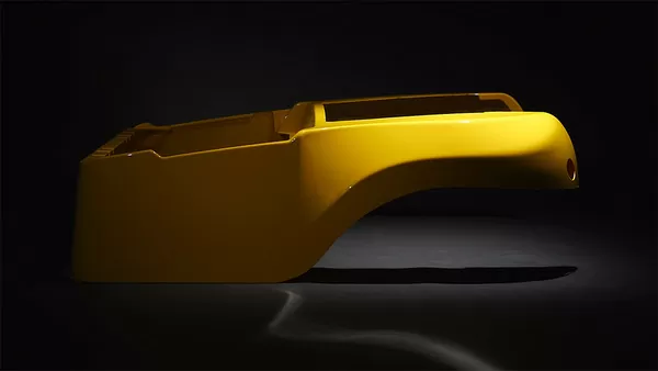
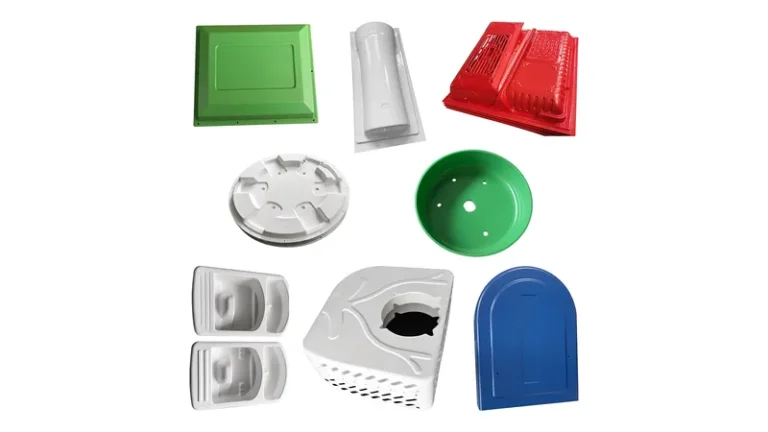
Sourcing formed plastic parts starts with a vocabulary problem: one supplier quotes thermoforming, another quotes vacuum forming, and the price gap between them is sometimes zero and sometimes significant. The confusion is understandable, because vacuum forming sits inside the thermoforming family rather than beside it. This article clears up the terminology first, then goes into the parameters that actually decide part quality — sheet temperature windows, forming forces, draw limits, trimming strategy and the test standards behind a reliable housing, cover or tray.
- Thermoforming is the process family; vacuum forming is its most widely used variant, driven purely by atmospheric pressure acting through a vacuum.
- Pressure forming adds positive air pressure on top of vacuum, holding sharper detail and texture on cosmetic surfaces.
- Heavy-gauge work runs on cut sheet from roughly 1.5 mm up to 15 mm; deep draws need predraw, plug assist and vented tooling.
- Material behaviour — sag temperature, heat deflection temperature, flammability rating — sets the process window before any machine setting does.
- Trimmed outlines follow the forming tool on a 5-axis machining centre, so tolerance planning should separate formed surfaces from machined edges.
- Validate with standardized tensile and flammability tests on the processed sheet, not with visual inspection alone.
What Is the Difference Between Thermoforming and Vacuum Forming?
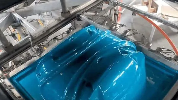
Thermoforming is the umbrella process: a plastic sheet is heated until it softens and is then pressed against a mold by mechanical or pneumatic force. Vacuum forming is the specific variant where that force comes from a vacuum drawn between the sheet and the mold, so atmospheric pressure does the work. Every vacuum-formed part is thermoformed, but thermoforming also covers pressure forming, twin-sheet forming and mechanically assisted methods.
In practice the label tells you about scope, not hardware. A shop forming 15 mm structural sheet and a packaging shop forming 0.5 mm film both describe their work as thermoforming. When you are sourcing enclosures, machine guards, trays or structural panels, the questions that matter are sheet thickness, draw depth, surface detail and certification — and those are where the variants genuinely separate.
For a neutral process definition, the CustomPartNet thermoforming overview is a useful reference; for a compact side-by-side of the two most quoted variants, see this comparison of thermoforming and vacuum forming.
"Thermoforming and vacuum forming are competing processes, so quotes using different terms describe different equipment."False
The two terms describe scope, not separate machines. One heated-sheet forming line runs both variants, so a quote naming the other term usually reflects vocabulary rather than capability. Treating the words as competing processes leads buyers to request duplicate quotations and lose weeks during supplier selection.
"Every vacuum-formed part is a thermoformed part, but not the reverse."True
Vacuum forming is the subset of thermoforming in which a vacuum between sheet and mold supplies the forming force. The family also includes pressure forming, twin-sheet forming and mechanical methods, each adding forces or features vacuum alone cannot deliver. Specify the variant in your drawing notes, not just the process family.
How Deep Can Vacuum Forming Pull a Thick Sheet?
With vacuum alone, a well-designed heavy-gauge1 part typically draws to a depth ratio of about 1:1 against its smallest footprint; beyond that, wall thinning concentrates at the base radii and surface detail washes out. Deeper geometry remains achievable, but it depends on predraw, plug assist and controlled sheet temperature rather than on heat alone.
On vacuum alone the pressure difference is capped by the atmosphere: roughly one bar at sea level, less after losses through mold vents and plumbing, so an effective 0.6–0.9 bar at the sheet is a realistic heavy-gauge range. Wall distribution follows the draw ratio2, so a deep housing may thin to 30–50 % of the original gauge at its deepest corners. The levers are consistent across materials — start the sheet with a predraw box, pre-stretch it with a plug assist3, balance vent placement, and hold sheet temperature in a window set by the material’s softening behaviour4 rather than by trial and error.
Pressure forming changes this picture by adding positive air pressure — commonly in the 0.3–0.7 MPa range on heavy-gauge presses — on the free side of the sheet. The added force pushes texture and detail into the mold surface and supports deeper draws, which is why cosmetic enclosures and front panels are its natural applications.
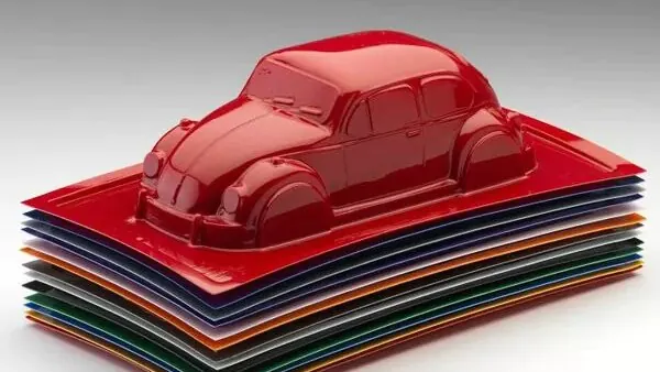
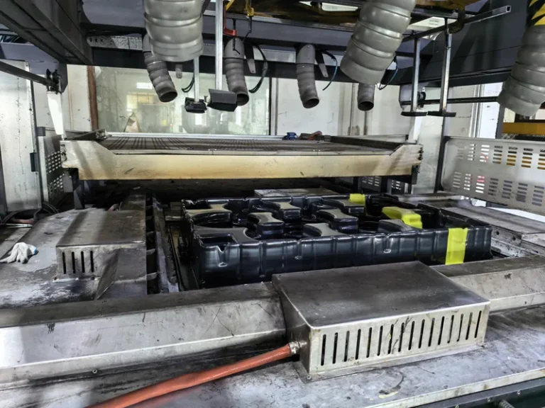
ZetarVac forms sheet from 0.5 to 15 mm on more than 20 vacuum forming and thermoforming machines, with a maximum forming length of about 2,500 mm. For large equipment covers and housings, that often means a single-piece formed skin is feasible where a two-piece assembly would otherwise be forced on the design.
These constraints explain why deep-draw failures look the way they do. Uniform thinning with crisp detail means the process window is right; corner starvation, thin base radii or washed-out texture usually point to missing tooling help rather than to a wrong machine setting.
"Vacuum pressure alone will pull any thick sheet into a deep cavity if you simply heat it more."False
Extra heat does not replace forming force. Overheated sheet sags uncontrollably, thins at the deepest radii and can mark against the mold, while the effective vacuum stays capped near one bar. Deep heavy-gauge draws need predraw, plug assist and vented tooling, and parts formed too hot drift out of tolerance batch after batch.
"Deep-draw heavy-gauge parts are a tooling and sequencing problem, not a heat problem."True
A predraw box starts the sheet down the cavity before full vacuum, a plug assist stretches material where it would otherwise starve, and vent sizing governs how quickly the vacuum reaches each surface. These tooling decisions set wall distribution, and wall distribution decides whether the part passes assembly checks across a production run.
Which Materials Suit Heavy-Gauge Vacuum Forming?
Material selection sets the process window before any machine setting does. ABS is the default engineering choice for equipment housings, cases and guards because it forms predictably and accepts paint and texture. PC brings impact resistance and transparency to clear guards and protection covers, while HDPE and PP carry the industrial trays, liners and storage boxes where chemicals, moisture and repeated handling are present.
PMMA supplies the optical clarity behind luminaire covers and retail display work, and PC/ABS balances impact and rigidity for automotive interiors. ASA extends housing work to outdoor exposure; PA6/PA66 and POM serve special industrial structural and precision parts; soft TPE, TPU and TPV grades complete the range for liners, seals and flexible protection components.
| Material | Typical formed applications | Property to verify first | Watch-out |
|---|---|---|---|
| ABS | Equipment housings, cases, guards | Impact strength, finish quality | Needs flame-retardant grades for many enclosures |
| PC | Clear guards, protection covers | Impact and transparency | Drying before forming; scratch sensitivity |
| HDPE | Industrial trays, liners, storage boxes | Chemical and moisture resistance | Higher shrinkage; softer detail |
| PP | Automotive interiors, trays, boxes | Fatigue and chemical resistance | Narrow sag window in heating |
| PMMA | Clear covers, luminaires, display parts | Optical clarity | More brittle failure mode at edges |
| PC/ABS | Automotive interiors, housings, guards | Balanced impact and rigidity | Blend-specific forming window |
For enclosures around electrical equipment, UL 94 defines the flammability ratings — from HB through V-0 — that many formed housings and covers must demonstrate before they can be specified, so fix the material grade and the test plan together rather than treating certification as late paperwork. Where heat is present, heat deflection temperature5 matters just as much, because a cover that forms beautifully can still distort next to a heat source if the grade was chosen on datasheet highlights alone.

The plant’s material library spans rigid engineering sheet — ABS, PC, HDPE, PP, PMMA, PA6/PA66, POM and PC/ABS — together with ASA for outdoor exposure and soft TPE, TPU and TPV grades for liners, seals and flexible protection parts. A housing, its soft liner and a clear PC or PMMA cover can therefore be formed and trimmed within one supplier and one material approval route.
How Are Tolerances and Quality Verified on Formed Parts?
Formed surfaces carry naturally wider tolerances than machined edges: a practical expectation is roughly ±1–2 % of the forming dimension on formed features, while a 5-axis trim pass holds machining-class limits on outlines and cut-outs. Verification therefore splits into two plans — dimensional checks on trimmed geometry and standardized material tests on the processed sheet.
ISO 527-2 specifies the tensile test method used to determine the tensile properties of plastic sheet and formed parts, so tensile data measured on the actual processed sheet — not only on the resin datasheet — is the evidence base behind any structural claim a supplier makes in a design review.
On heavy-gauge parts the trimmed outline follows the forming tool, which means the forming tool, the trim fixture and the 5-axis programme are maintained as one system. When a dimension drifts in production, check tooling condition and sheet batch before blaming cycle settings.
On thick sheet, thickness itself is a measurement item: verify incoming gauge at several sheet positions, because a large panel formed from sheet at the thin end of its own tolerance will lose wall at the deepest draw no matter how well the cycle runs. Recording sheet batch numbers alongside inspection results lets you separate material variation from process variation when something moves.
"First article approval proves the whole production run will stay within tolerance."False
A first article is one sample formed under one set of conditions. Heavy-gauge quality depends on repeatable sheet temperature, vacuum timing and tooling condition across shifts and sheet batches, so a single accepted part says little about run stability. Lock the process window and define sampling before releasing production.
"Run stability comes from a documented process window, not from a good first sample."True
Specify sheet temperature range, vacuum level, forming and cooling times and trim datums as a window, then verify capability with parts sampled across shifts and sheet lots. This converts acceptance from a one-time event into a checkable production standard, which is what a manufacturing engineer actually needs for part release.
Vacuum Forming or Pressure Forming: Which Should You Specify?
Specify vacuum forming when the program needs scale, moderate tooling cost and a robust engineering surface — machine covers, trays, liners and structural panels. Specify pressure forming when a visible exterior with sharp texture, lettering or crisp radii justifies the higher tooling and press cost. Most heavy-gauge industrial programs sit comfortably on the vacuum side.
| Attribute | Vacuum forming | Pressure forming |
|---|---|---|
| Forming force | Atmospheric pressure through vacuum, up to about 1 bar | Vacuum plus positive air pressure, commonly 0.3–0.7 MPa |
| Surface detail | Good on the free surface; softer texture transfer | Sharp texture and lettering on the pressure side |
| Tooling | Vented mold, lower cost, fast to revise | Pressure-sealed mold and clamping, higher cost |
| Typical parts | Machine covers, trays, liners, structural panels | Cosmetic enclosures, front panels, display covers |
| Cost per part | Lower tooling amortization | Higher, justified on visible surfaces |
Cost structure differs by variant. Vacuum tooling is usually cast or machined aluminum with vented surfaces, so prototype and production tools stay affordable and quick to revise. Pressure forming needs a sealed pressure box, stronger clamping and a mold that survives positive pressure, so tooling cost rises while per-part cosmetic quality improves. Decide by counting how many surfaces of the part a customer actually sees.
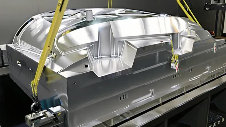
Tooling geometry comes first. Male tools form the inside surface and give the part its outer wall by stretching, while female tools deliver crisp outside detail but thin the sheet where it bridges the cavity. The choice between male and female vacuum forming molds affects wall distribution, draft angles and vent layout before any forming cycle starts, so review it at the drawing stage rather than after the first trial.
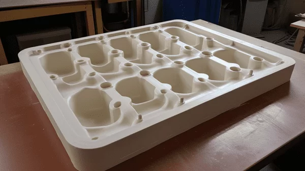
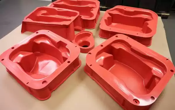
Reference programs. A multi-cavity ABS seedling tray for agricultural seedling raising, a large curved PC housing with custom cut-outs, mounting holes and reinforcement for medical and diagnostic equipment, and a high-clarity PMMA display cover for retail settings are all ordinary outcomes of this material-and-tooling logic — different variants of one heated-sheet process, selected by geometry and service environment.
ZetarVac’s reference monthly capacity is about 100,000–200,000 pieces, and prototyping, small batch and large batch production are all supported on the same plant floor. A process window proven on prototype tooling can therefore be scaled without moving the program to a different plant or re-qualifying a new supplier mid-run.
FAQ
Is vacuum forming a type of thermoforming?
Yes. Vacuum forming is the most common thermoforming variant: the heated sheet is pressed against the mold purely by atmospheric pressure acting through the vacuum. Pressure forming and twin-sheet forming are sibling variants that add forces or a second sheet.
How thick can the sheet be for heavy-gauge vacuum forming?
Heavy-gauge work generally starts around 1.5 mm; this plant processes sheet from 0.5 to 15 mm, so thin packaging-grade parts and thick structural panels share one forming environment. The upper limit for a specific part depends on material, draw depth and cycle time.
Does vacuum forming suit large parts?
Yes. With a maximum forming length of about 2,500 mm, single-piece covers and enclosures for large equipment are a standard heavy-gauge application, and 5-axis trimming keeps the cut outline true to the forming tool.
Can vacuum forming produce cosmetic surfaces?
Plain vacuum forming gives a moderate surface with softer texture transfer. When the exterior is customer-visible and needs sharp texture or lettering, pressure forming is the variant to specify, at the cost of more complex tooling.
How many parts justify thermoforming tooling?
Thermoforming tooling is considerably cheaper than injection tooling for large parts, so programs run from prototype and small batches up to large series. The break-even depends on part size and material, so ask suppliers to quote prototype and production tooling separately — it makes the scale-up path visible before you commit.
To keep researching before you shortlist suppliers, review the vacuum forming process overview at ZetarVac, or explore how a China-based heavy-gauge forming partner structures programs from prototype through large batch production.
-
Heavy gauge: thermoforming on cut sheet thicker than roughly 1.5 mm, processed sheet by sheet rather than from roll-fed thin film. ↩
-
Draw ratio: the ratio of formed part depth to the smallest dimension of its forming footprint; higher ratios concentrate wall thinning. ↩
-
Plug assist: a mechanical plug that pre-stretches the heated sheet into the cavity before vacuum or pressure completes forming. ↩
-
Sag temperature: the sheet temperature range at which a heated plastic sheet starts to droop under its own weight, signalling it is ready to form. ↩
-
HDT: heat deflection temperature, the temperature at which a plastic specimen deflects a specified amount under a defined flexural load. ↩