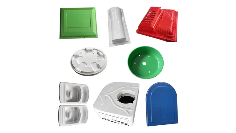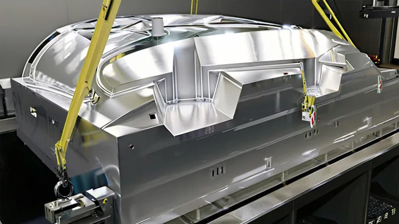
In heavy-gauge thermoforming, the mold is not a commodity purchase — it is the component that decides cycle time, surface quality, and how long your unit cost stays competitive. Buyers comparing aluminum against resin tooling usually start with price, then discover the real variables: thermal conductivity, durability across forming cycles, and how often the part design will still change. This guide evaluates both mold families the way a process engineer would, so you can match tooling to volume, sheet material, and part geometry before committing budget.
- Mold material sets the ceiling on cycle time, surface detail, and tooling life — not just the tooling budget.
- Machined and cast aluminum molds suit production volumes, textured surfaces, and parts that need fast, even cooling.
- Cast resin and filled-epoxy molds fit prototypes, bridge tooling, and short runs where geometry may still change.
- Sheet gauge and forming temperature decide how much thermal durability the mold surface needs.
- Plan the trim fixture together with the mold, because the trimmed outline follows the forming tool.
- Parts validated on a resin pilot mold must be re-qualified on the production tool before volume release.
What Mold Types Are Used in Heavy-Gauge Thermoforming?
Heavy-gauge thermoforming shops work with four main mold families: machined aluminum, cast aluminum, cast or filled-epoxy resin, and wood or composite tooling. Aluminum dominates production work, while resin and composite tools carry prototyping and short runs. The real decision variables are thermal conductivity, surface durability, and the number of cycles the tool must survive.
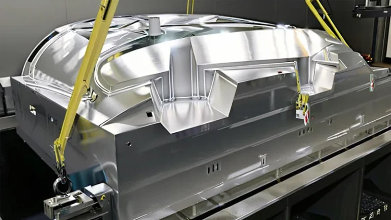
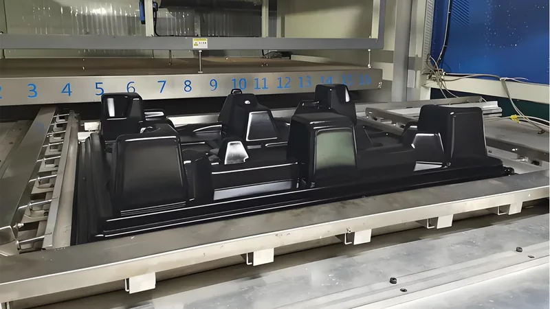
Machined aluminum starts as a solid billet or thick plate cut on a CNC machining centre. It gives the tightest control over wall transitions, draft, and vent placement, and it is the only practical route to deep draws with machined cooling channels behind the forming surface. Cast aluminum pours a foundry alloy against a pattern, which lowers cost on large, relatively simple cavities but introduces porosity that must be sealed before the tool sees vacuum forming duty.
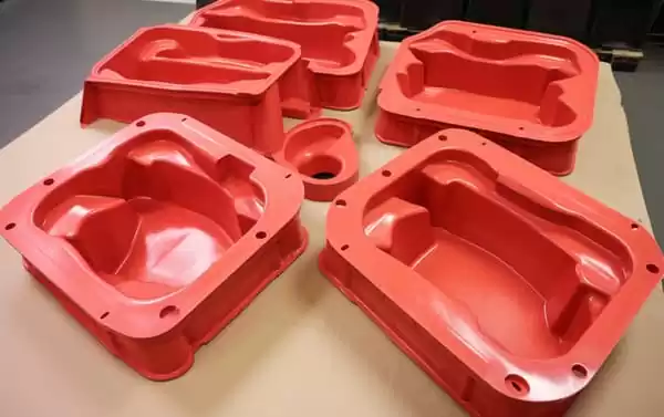
Resin tooling covers several chemistries: filled epoxy pastes cast over a master model, machinable polyurethane board, and composite lay-ups. All of them share one trait — low thermal conductivity compared with aluminum. That is not automatically a flaw. Slower heat removal is acceptable when you are pulling five prototypes, and it becomes a defect source only when a resin tool is pushed into sustained production without a thermal review.
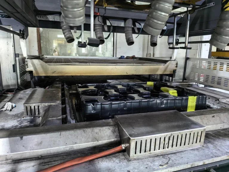
The same tooling logic applies whether the process runs as straight vacuum forming or as pressure forming, where a pressure box above the sheet drives it into finer detail. Pressure forming raises the contact force on the mold surface, which makes surface durability and vent design even more important in the material decision.
For background on how the forming process itself works before tooling is discussed, see our vacuum forming overview and our heavy-gauge thermoforming guide.
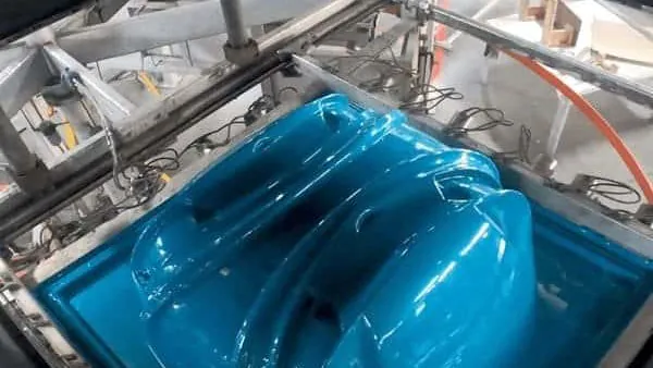
ZetarVac processes sheet from 0.5 to 15 mm on more than 20 vacuum forming and thermoforming machines, with forming lengths up to about 2,500 mm. A plant working across that gauge and size range typically runs a mixed mold fleet — aluminum production tools for long-running parts and resin tools for validation — so the material question rarely has a single answer.
Where Aluminum Molds Earn Their Cost
Aluminum’s decisive property is thermal conductivity — roughly 100–150 W/m·K for common forming alloys, against well under 1 W/m·K for filled epoxy. In practice, the sheet contacts a mold that pulls heat out quickly and evenly, which shortens cycle time and reduces the differential shrinkage that warps large panels. On a 6 mm ABS housing shell, the gap between an aluminum tool and a resin tool is measured in seconds per cycle, and those seconds compound over tens of thousands of pieces.
Aluminum also holds surface detail. Mold makers can bead-blast, peen, or chemically etch textures directly into the cavity, and those textures survive long production lives. Texture is not cosmetic only: a fine grain hides pull marks, evens out gloss, and lets vacuum evacuate uniformly across flat surfaces — the difference buyers notice between an acceptable housing and a rejected one. Draft interacts with texture as well, because textured cavities generally need an extra degree or so of release angle1.
"Aluminum tooling is always too expensive for runs below a few thousand parts."False
A machined aluminum tool does cost more up front, but cast aluminum and simplified constructions close much of that gap. When cycle time, scrap rate, and requalification cost are counted together, aluminum frequently pays back even at modest volumes.
"Cycle time differences between mold materials compound into real unit-cost gaps."True
A 15–25 second cycle penalty on a resin tool sounds trivial until it is multiplied across a full release. Over 20,000 pieces, that penalty adds several hundred machine hours, which can erase the margin the cheaper tool appeared to save.
The counterweight is lead time and cost of change. A CNC aluminum cavity takes weeks to cut, and every geometry revision means new machining. That is why disciplined teams settle wall, draft, and radius questions before metal is ordered — our DFM checklist for heavy-gauge thermoformed parts and molds walks through that review step by step.
Where Resin and Filled-Epoxy Molds Fit
Resin tools exist because early-stage geometry changes. Casting a filled-epoxy mold over a CNC-machined or 3D-printed master takes days rather than weeks, and a revision means recasting the affected area instead of re-machining billet. For functional prototypes, trade-show units, or a first sampling round, that speed often outweighs cycle performance.
Resin’s limits are thermal. Filled epoxies and polyurethane tooling boards soften far below aluminum’s working range, and the useful indicator is heat deflection temperature: ISO 75-2 defines how the heat deflection temperature of a plastic is measured under a specified flexural load, and it constrains which resin grades can survive repeated contact with sheet heated to forming temperature — commonly in the 120–180 °C range depending on material — without gradually creeping out of geometry2.
Mold makers also watch the coefficient of thermal expansion3 between the master model and the cast material, because a mismatch bakes distortion into the tool from the first cure. And cast resin is porous: outgassing through micro-pores produces pinhole marks on formed parts unless the cavity is properly sealed and polished4.
"Resin molds cannot produce dimensionally accurate parts."False
A well-sealed, properly cured resin mold holds tolerances that are fully adequate for prototype and short-run qualification. Accuracy problems come from porosity, thermal creep, or a worn surface — all manageable material and process issues, not a fundamental limit of resin tooling.
"Resin molds need an explicit thermal ceiling before any production use."True
The mold material’s heat deflection temperature and the sheet’s forming temperature must be checked against each other. A resin tool run near its softening range deforms slightly with every cycle, and the resulting dimensional drift builds gradually enough to escape routine first-article checks.
How Should Volume and Part Size Drive the Choice?
Use expected total cycle count as the primary criterion, then refine by part size and surface requirement. Below roughly 200–500 pieces on a stable drawing, resin usually wins on cost and speed. Beyond that — or whenever the part is a long-running product — aluminum’s cycle performance and durability repay the higher tooling investment.
| Selection factor | Machined / cast aluminum | Cast resin / filled epoxy |
|---|---|---|
| Tooling lead time | 3–6 weeks, geometry-dependent | Days to about 2 weeks |
| Relative tooling cost | High | Low to moderate |
| Cycle time | Shortest; fast, even heat removal | Typically 15–25 s longer on thick parts |
| Surface texture | Machined, peened, or etched; very durable | Cast-in or coated; wears sooner |
| Thermal durability | Effectively unlimited at forming temperatures | Limited by heat deflection temperature |
| Design revisions | Re-machining; costly after cutting | Recast or rework locally |
| Best fit | Production parts, textured cosmetic surfaces | Prototypes, bridge tooling, short runs |
Part size shifts the comparison in a less obvious way. Large panels and enclosures — the kind formed at lengths up to 2,500 mm — amplify every cooling inequality, because the sheet edge cools faster than the centre and the mold either compensates or locks in warp. On big parts, aluminum’s even heat extraction is not a luxury; it is often what keeps a flat panel flat. The caveat is cost: a full-size machined aluminum cavity for a two-meter housing is a serious investment, which is why some programs validate size and fit on a resin tool, then cut aluminum for production.
ZetarVac supports prototyping, small batch, and large batch production in one plant, with 45+ production lines in total. Staging tooling — resin until the design freezes, aluminum for release — fits that workflow, but only when the qualification plan states it from the start.
Which Defects Trace Back to Mold Material?
Several recurring heavy-gauge defects point at the mold rather than the process: poor texture transfer, gloss spotting, pinhole bubbling, weak detail in deep draws, and warp from uneven cooling. Each leaves a distinct fingerprint that tells you whether the cavity, the vacuum system, or the sheet is the actual source.
Weak or inconsistent detail is often a mold problem in disguise. Vacuum forming pulls the sheet against the cavity at a typical line vacuum of roughly -0.08 to -0.095 MPa; if the vent pattern is too sparse, or a resin surface has sealed its own micro-channels, detail loss shows up first in deep corners. Machined aluminum lets the mold maker place vents exactly where the sheet lands last, which is why deep draws with crisp corners are almost always aluminum territory.
Surface defects tell the other half of the story. Gloss variation and spotting trace to texture wear or contamination, pinholes trace to porosity in cast tools, and haze or streaking on a resin mold usually means the seal coat is breaking down. Formed parts still need mechanical validation — tensile testing of sheet and parts per ISO 527-2, which defines how tensile properties of plastics are measured, and flexural testing per ASTM D790 for stiff panels and enclosures. But when the same defect repeats across different material lots, the mold becomes the prime suspect.
"Once a mold makes one good first article, tooling quality is proven."False
A first article proves the cavity geometry at that moment, not the tool’s behaviour across thousands of thermal cycles. Resin creep, texture wear, and seal-coat breakdown all develop gradually, so tooling needs re-verification after the first few hundred shots and periodically thereafter.
"Mold material choice should be re-reviewed at the production release stage."True
Tooling selected during development was optimized for speed and change tolerance, not sustained output. Before volume release, re-check cycle time, surface condition, and dimensional stability against the production plan, and requalify parts on the production tool rather than inheriting prototype results.
FAQ
How long does an aluminum thermoforming mold last?
With reasonable care, an aluminum production mold commonly runs for hundreds of thousands of cycles. The practical life limit is usually texture wear or an engineering change in the part, not structural failure of the tool itself.
Can a resin mold ever be the final production tool?
Yes, when volumes stay low and forming temperatures are moderate. Mid-gauge parts in materials such as PVC or LDPE form at lower temperatures, and a well-sealed resin tool can carry short ongoing runs economically. The key is making that decision deliberately instead of letting a prototype tool drift into production.
Does sheet material affect the mold material choice?
It does. High-temperature materials such as PC, PMMA, and PA6 require forming temperatures that narrow the resin options considerably, while PVC, HDPE, and ABS are more forgiving. Glass-filled sheet is harder on mold surfaces and accelerates texture wear on any tool material.
How much does mold choice change cycle time?
On thick-gauge work, expect roughly 15–25 seconds per cycle of difference, driven almost entirely by heat removal rate. Exact values depend on sheet thickness, material, and part geometry, so treat these as engineering ranges rather than quotations.
Do I need a separate trim fixture along with the mold?
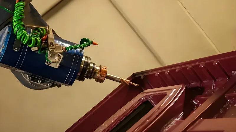
Yes. Formed parts are trimmed on 5-axis CNC equipment, and the trimmed outline follows the forming tool’s registration, so the mold and the trim strategy should be engineered together and quoted together.
To evaluate your housing, tray, or enclosure project against both mold options, send your drawings and talk to an engineer via our China vacuum forming manufacturer page. We will review draft, wall, and tooling trade-offs with you before any commitment is made.
-
Draft angle: The taper added to mold surfaces so a formed part releases cleanly; textured cavities generally require more draft than polished ones. ↩
-
HDT: Heat deflection temperature — the temperature at which a plastic test bar deflects a specified amount under a standard flexural load, used to rate resistance to softening under heat and stress. ↩
-
CTE: Coefficient of thermal expansion — how much a material expands per degree of temperature change; a mismatch between a resin mold and its master model builds distortion into the tool. ↩
-
Porosity: Microscopic pores in cast tool materials that trap air and outgas under vacuum, leaving pinhole marks on formed parts unless the mold surface is sealed. ↩