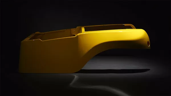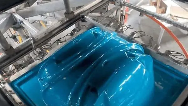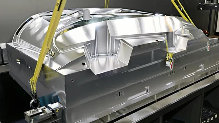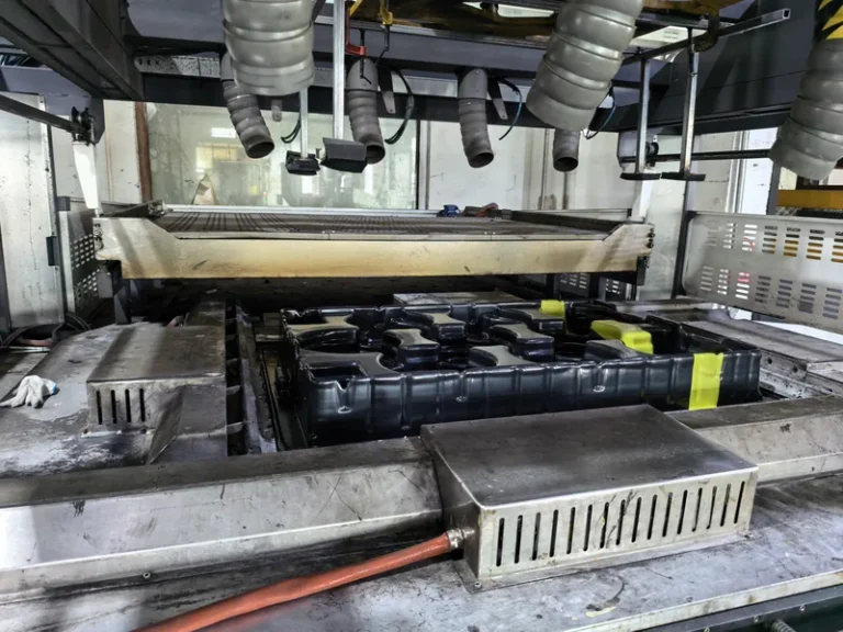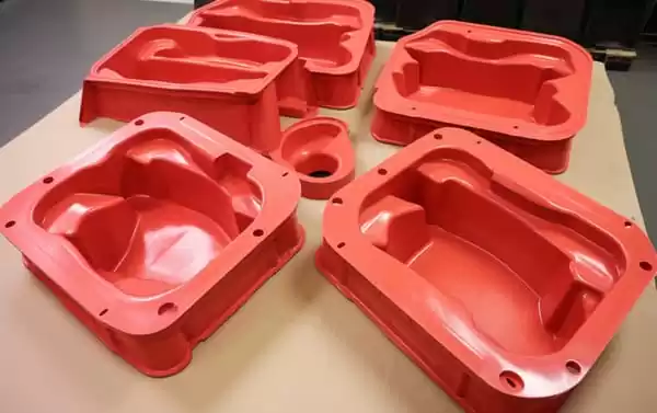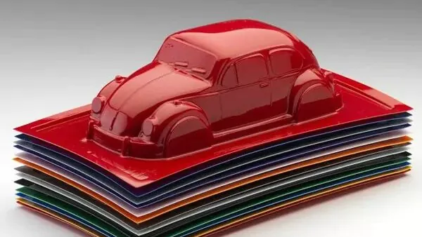
Choosing between a raised tool and a cavity tool looks like a shop-floor detail, but in heavy gauge thermoforming it decides which surface of the part carries the detail, where the wall thins most, how much draft the drawing needs, and what the tooling will cost. Buyers who lock the mold style too early often find out late that a cosmetic surface or a critical dimension ended up on the wrong side. The basic mechanics of the process — heat, seal, draw, cool — are the same everywhere and are well described in references such as CustomPartNet’s thermoforming overview. The mold style, however, is where two quotes for the same part can diverge sharply.
- A positive (male) mold forms the inside of the part; a negative (female) mold forms the outside, so the mold style decides which surface receives texture, detail and tolerance control.
- Wall thinning follows draw ratio and corner geometry, not mold style alone; deep female draws concentrate thinning at the cavity floor unless the sheet is plug-assisted.
- Positive tooling needs more draft — an engineering starting range is 2–5 degrees — because the cooled part grips the mold; female cavities often release at 1–2 degrees.
- Tooling cost tracks surface detail, venting and cooling design rather than the mold orientation itself.
- Prototype on real material before committing: ZetarVac supports prototyping through large batches, processes sheet from 0.5 to 15 mm, and forms lengths up to about 2,500 mm.
What Is a Positive Mold in Vacuum Forming?
A positive mold — usually called a male or drape mold — is a raised tool. The heated sheet is clamped, then draped down over it, so the first surface to touch the tool becomes the inside of the finished part. Any detail machined into the tool therefore shows up on the inner surface, while the outer surface forms freely against air.
Because the sheet lands on the top of the mold at essentially full gauge, the top face of a male-formed part keeps close to the original sheet thickness. The wall thins as the sheet stretches down the sides, with the thinnest zones at the lower corners and around sharp radii. That distribution is an advantage when the inside of the part must be dimensionally controlled against a tool: trays, liners and structural panels formed over cores are typical male-mold work.
Draft is the discipline that catches teams out. As the sheet cools it shrinks onto the male core and grips it, so vertical walls need generous draft — commonly 2 to 5 degrees, more on deep draws or textured tools — or the part hangs up on demold.
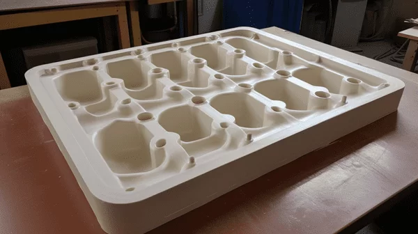
ZetarVac’s ABS vacuum-formed seedling tray is a working reference: a multi-cavity heavy-gauge thermoforming part where tray size, cavity count and cell geometry are all customized for agricultural seedling raising. Cell walls formed over raised features behave exactly like male-mold skirts, so full-gauge tops, corner thinning and deliberate draft drive the whole design.
What Is a Negative Mold in Vacuum Forming?
A negative mold — a female or cavity mold — is a recessed tool. The heated sheet is sealed over the cavity rim and drawn down into the cavity, so the mold surface forms the outside of the part. Texture, part numbers and crisp external detail all appear on the surface the buyer actually sees.
The rim of a female-formed part stays close to full sheet gauge, while the bottom corners of a deep cavity are the thinnest zones. Vent holes and vacuum routing decide how quickly air escapes; a deep cavity with narrow radii traps air and leaves poor definition unless the sheet is prestretched or pushed in with a plug. Between closely spaced female features the stretching sheet can bridge and form webs, which is why webbing inspection belongs on the first-article checklist for any cavity tool.
Draft is friendlier on this style: the cooled part shrinks away from the cavity wall, so 1 to 2 degrees is often workable on straight pulls, and texture depth rather than shrinkage usually sets the minimum.

ZetarVac’s PC vacuum-formed medical equipment housing shows the negative-mold payoff: a large, complex curved housing with custom cut-outs, mounting holes and reinforcement for diagnostic equipment. Forming against a cavity keeps the cosmetic outer surface under tool control, and the material grade is selected against UL 94[^ul94], the flammability standard that classifies whether a plastic specimen extinguishes or spreads flame after ignition — a requirement for many electrical enclosures.
Positive vs Negative Molds: Side-by-Side Comparison
The table below condenses the trade-offs into the attributes that actually move a design decision. Treat the draft and thinning rows as engineering starting ranges — they shift with material, draw depth and texture.
| Attribute | Positive (male) mold | Negative (female) mold |
|---|---|---|
| Mold contact surface | Inside of the part | Outside of the part |
| Detail and texture appear on | Inner surface | Outer surface |
| Thickest zone | Top of the tool (full gauge) | Rim of the cavity (full gauge) |
| Thinnest zone | Lower skirt corners | Cavity floor corners |
| Typical draft | 2–5 degrees, more when textured or deep | 1–2 degrees often workable |
| Demold behavior | Part grips the tool as it cools | Part shrinks away from the wall |
| Common failure mode | Hang-up on demold, corner thinning | Webbing, trapped air, poor floor detail |
| Typical parts | Trays, liners, panels over cores | Housings, covers, textured enclosures |
One more nuance: tolerance sides. Dimensions formed against the tool replicate the tool geometry closely; the free surface floats with sheet gauge and process window. Decide early which print dimensions are critical and make sure they sit on the tool side of the chosen style.
How Does Wall Thickness Change on Each Mold Style?
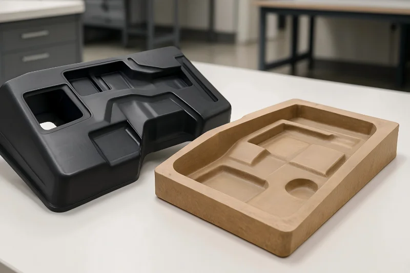
On a positive mold the sheet lands on the tool top at full gauge and thins as it stretches down the sides; on a negative mold the rim is thickest and the cavity floor corners are thinnest. In both cases the magnitude is governed by the draw ratio1 — formed surface area relative to the original flat sheet — and by how the sheet is prestretched, not by the mold style alone.
A practical screen: a draw ratio near 1:1 usually forms without drama; between 1:1 and about 1.5:1, watch corner radii and sheet temperature; beyond roughly 1.5:1, plan plug assistance or sheet pre-blow to move material where the corners need it. Radii matter as much as depth — a 5 mm inside radius distributes stretch that a 2 mm radius concentrates into a thin ring. Materials differ too: PC and ABS tolerate deep draws better than rigid PP at the same gauge.
Thinning matters because stiffness falls faster than mass. Section stiffness scales roughly with the cube of thickness, so a panel that thins 20 percent loses close to half its bending stiffness. Formed panels and enclosures are therefore usually validated with ASTM D7902, the standard test method that specifies the three-point bend measurement of flexural properties for plastics and lets you compare stiffness across sheet lots and tool styles. Verify the prediction with a measured wall-thickness map — ultrasonic or cut sections — on the first article, not with the mold label.
"A negative mold always produces thinner walls because the sheet is stretched down into a cavity."False
The claim confuses stretch direction with stretch amount. A shallow female draw can keep walls close to gauge, while a tall male drape can thin corners severely; what matters is draw ratio, corner radii and prestretch. Sizing the tool on this assumption delivers a wall map that misses spec at the corners.
"Wall thinning follows the draw ratio and stretch path, not the mold style alone."True
Evaluate each geometry on its own numbers. Estimate the local draw ratio, check the radii, and plan plug assist or pre-blow where thinning would concentrate. Then confirm with a measured wall-thickness map on the first article.
How Much Draft Does Each Mold Style Need?
Positive tooling usually needs the most: an engineering starting range is 2 to 5 degrees on vertical walls, and more on deep draws or textured tools. Negative cavities often release at 1 to 2 degrees because the part shrinks away from the wall as it cools. Both ranges depend on material shrinkage, part depth and texture depth.
The mechanism is thermal shrinkage working in opposite directions. On a male core the contracted part clamps down like a collar and must be peeled off; on a cavity wall the same contraction pulls the part clear. Texture adds mechanical lock on either side, so a common shop rule is to add roughly one degree of draft per 0.25 mm of texture depth. Low-shrink materials such as PC buy some margin, while polyolefins with higher shrinkage demand the upper end of the range. When a drawing truly requires near-vertical male walls, plan for mechanical ejection or a stripper feature instead of pretending the draft is optional.
"Draft requirements are identical for positive and negative tooling, so one CAD template covers both."False
Draft is set by demold physics, and the physics differ. A cooled part grips a male core and must be peeled off it, while it pulls away from a cavity wall. Applying a uniform 1-degree rule to male tooling produces parts that jam on demold or distort on ejection.
"Positive tooling needs extra draft because the cooled part grips the mold as it shrinks."True
Start male verticals at 2–5 degrees, add draft for depth and texture, and check release on the first shots. If near-vertical male walls are non-negotiable, budget for mechanical ejection or move those walls to the female side of the design.
Which Mold Style Should You Choose for Your Part?
Start from where the cosmetic surface and controlled dimensions must sit: outer texture or external detail points to a negative mold, while inside-dimension control points to a positive mold. Then check draw ratio, draft and trim strategy before fixing the style.
Work the checklist in order: mark the cosmetic surface and the critical dimensions on the print; compute the draw ratio and check corner radii; confirm draft can be added on the tool side without breaking function; only then compare tooling cost between the viable styles. In most heavy gauge thermoforming projects this settles the choice in one pass, because the location of the cosmetic surface alone usually dictates the style.
"Mold style is mainly a cost decision, so the cheaper tool to machine is the right answer."False
A male and a female tool for the same part can be close in cost once detail, venting and cooling are equal, but they deliver different surfaces and different wall maps. Choosing on machine-hour quotes alone hands you a part whose cosmetic surface, draft or tolerances sit on the wrong side.
"Choose the mold style from where detail, draft and tolerances must sit, then optimize the tooling cost."True
Fix the functional requirements first: cosmetic surface, texture, critical dimensions, draw depth. Once the style is settled, cost is managed through tool material, cooling design and cavity count — levers that do not move the part’s engineering fundamentals.
Clarity parts follow the same logic with one extra constraint. ZetarVac’s PMMA vacuum-formed display cover — a high-clarity, curved retail display part — shows how an optically clean outer surface dictates the tool side and the polish specification; transmittance on such parts can be qualified against ISO 134683, the standard that specifies the measurement of total luminous transmittance for transparent plastics.
ZetarVac runs more than 20 vacuum forming and thermoforming machines across 45+ total production lines, processing sheet from 0.5 to 15 mm with forming lengths up to about 2,500 mm, and trims formed parts on a 5-axis CNC centre so the cut outline follows the forming tool. Because prototyping, small batches and large batches are all supported, a team can validate the mold style on real material before committing to production tooling.
FAQ
Can one part use both a positive and a negative mold?
Yes. Matched tooling — a male plug and a female cavity acting on the same sheet — is used when both surfaces need control or when wall distribution must be managed on deep draws. The trade-off is higher tooling cost and tighter registration between the two tools. A deeper comparison of the two tool styles is in our male and female vacuum forming mold guide.
Which mold style gives better cosmetic texture?
The surface that touches the mold takes the finish. Outer texture therefore belongs on a female (negative) tool, where the cavity wall is polished or textured and that finish transfers to the outside of the part. Inner cosmetic surfaces flip the logic to a positive tool.
Does mold style affect cycle time?
Far less than cooling design does. Both styles need even, channelled cooling and consistent sheet temperature; a deep cavity and a tall core cool slowly for similar reasons. Expect cycle-time differences from wall thickness distribution and cooling geometry, not from the mold’s orientation.
When does a female draw need plug assistance?
As a working rule, evaluate plug assist once the draw ratio exceeds roughly 1.5 to 1, or whenever the cavity floor has tight radii, crisp detail or thin sheet at the low end of the 0.5–15 mm range. The plug pushes extra material toward the floor before vacuum pulls it, moving thinning away from the corners.
Is pressure forming a different mold decision?
No — pressure forming keeps the same positive/negative logic and adds air pressure on the non-mold side to sharpen texture and detail. It suits textured outer panels where vacuum alone leaves soft definition. If the two process names blur together in your specification, our thermoforming vs vacuum forming explainer sorts out the terminology.
To go deeper on tooling choices, sheet materials and the forming process itself, explore the ZetarVac vacuum forming hub, or see how a China-based heavy-gauge vacuum forming manufacturer walks projects from prototype tooling to batch production.
-
Draw ratio: The ratio of formed surface area to the original flat sheet area, used to estimate how much the sheet must stretch and where it will thin. ↩
-
ASTM D790: The standard test method for flexural properties of plastics, a three-point bend test used to compare the stiffness of panels and enclosures. ↩
-
ISO 13468: The standard specifying the measurement of total luminous transmittance of transparent plastics, used to qualify clear formed parts. ↩