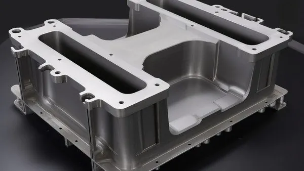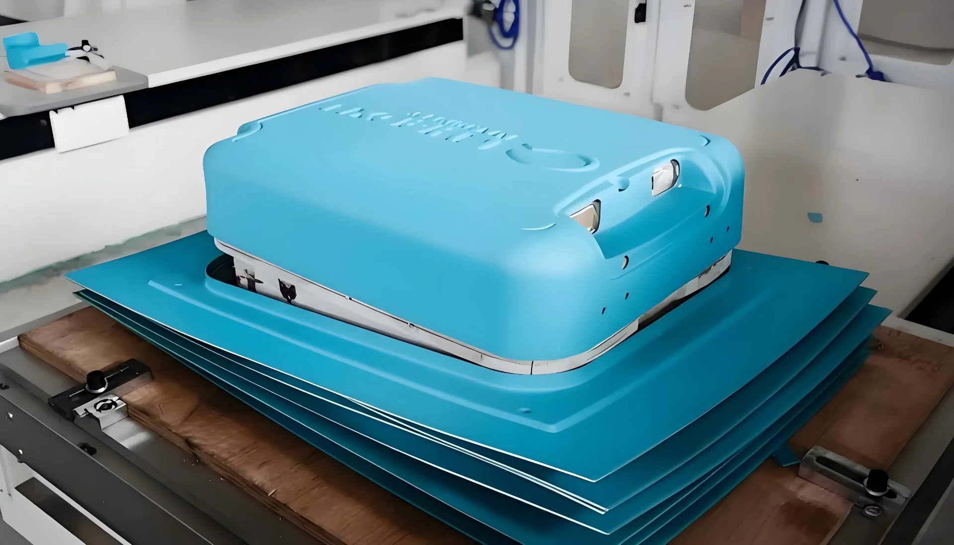
Every vacuum formed part starts the same way: a plastic sheet is heated until it softens, then pulled against a tool with vacuum. In heavy-gauge thermoforming, which side of that sheet touches the tool changes everything downstream. A male mold forms the inside surface of the part; a female mold forms the outside surface. That single decision drives wall thickness distribution, cosmetic quality, draft strategy, venting layout and tooling cost. This guide walks through the engineering differences so purchasing engineers and designers can question a tooling quotation with specifics instead of hunches.
- A male (plug) mold forms the part’s inside surface; a female (cavity) mold forms the outside surface. The sheet side touching the tool carries its detail and texture.
- Female tooling gives sharper exterior detail, molded-in texture and lettering, and is the default when the outer surface is cosmetic.
- Male tooling generally gives more uniform wall thickness on deep draws because the sheet drapes progressively over the plug.
- Formed parts never stay at sheet gauge: thinning concentrates where the sheet stretches first — upper corners on male tools, deep corners on female tools.
- Draft, vent holes, texture depth and the trimming datum must be agreed with the molder before the tool is cut.
- Mold orientation is a geometry decision, not a preference — reverse it late and the part redesign follows.
What Is a Male Mold in Vacuum Forming?
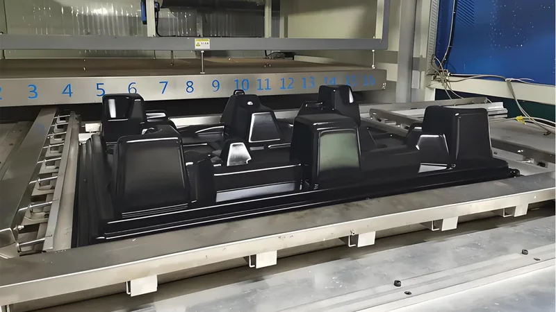
A male mold, also called a plug or buck, is a raised tool. The heated sheet is draped over it, so the part’s interior takes the tool’s shape and detail while the exterior is drawn down freely by vacuum. It is the natural choice for trays, liners and deep parts where inside geometry is functional and wall uniformity matters more than outside crispness.
Because the sheet lands on top of the plug first, that zone stays closest to the original gauge, while material stretching down the sides thins progressively. On deep draws the highest thinning appears at the upper corners, where the sheet turns from horizontal drape into vertical stretch. Designers therefore keep functional ribs, mounting bosses and stiffening geometry on the inside face, where they reproduce directly from the tool.
Air entrapment is the main process risk on a male tool. Vent holes1 — small holes drilled through the tool surface, spaced closer at corners and detailed zones — let trapped air escape so the vacuum can complete the pull. Their diameter and density are part of tooling design, not an afterthought: too large and they mark the part, too sparse and the sheet bridges.
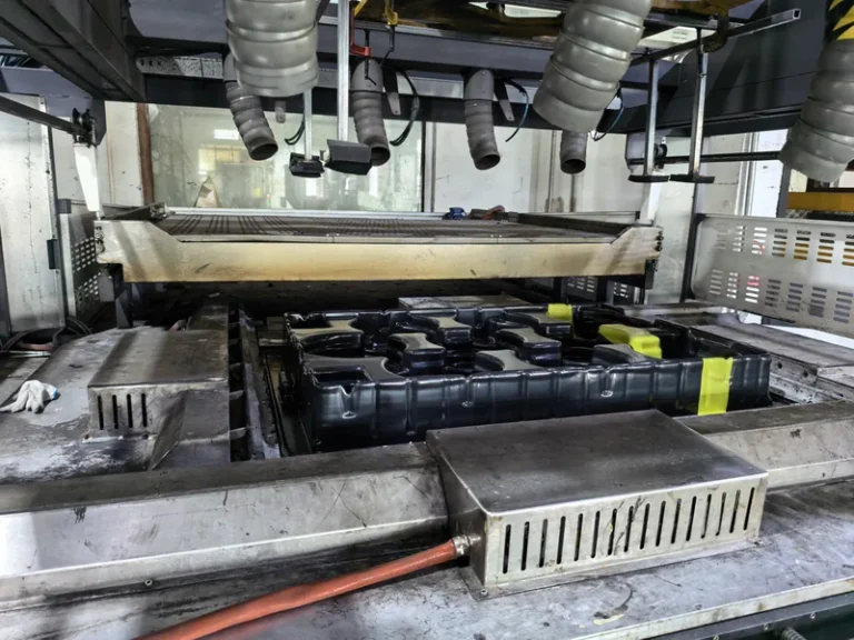
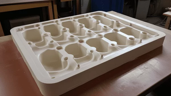
A multi-cavity ABS seedling tray, formed by heavy-gauge thermoforming, is a classic male-mold part. Cell geometry is defined from the inside, cavity count and cell pitch adapt to the customer’s seeding line, and the tray must release cleanly in high volumes. For tooling construction details, see this guide to male and female vacuum forming molds.
"Male molds need no draft because the part shrinks away from the tool."False
Shrinkage helps release on the free surfaces, but corners, texture and long vertical walls still lock onto a male plug. Without engineered draft, deep parts deform or hang up on ejection, and thin walls scrape thin exactly in the zones that are already the most stretched.
"Male tooling still needs engineered draft, sized by material and draw depth."True
Draft is set per material shrinkage and per draw depth, with more allowance on deep vertical walls and textured surfaces. Agreeing the values during part design keeps ejection clean and the thickness map predictable.
What Is a Female Mold in Vacuum Forming?
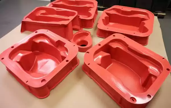
A female mold is a recessed cavity. The heated sheet is drawn down into it, so the part’s outer surface bears the tool’s finish — texture, lettering, sharp radii — while the inside forms freely under vacuum. It is the default route for equipment housings, machine covers and any part where the exterior is the visible, handled surface.
Detail fidelity is the payoff. Because the outer skin is pressed against a finished cavity surface, outside features reproduce directly, which is why cosmetic enclosures are almost always female-formed. The trade-off is thinning: the sheet stretches first around the rim and upper walls and arrives last at the bottom corners, so the deepest corners of a female-formed part are usually its thinnest. Where the draw is deep relative to the opening, webs2 — wrinkles of excess sheet bridging between features — appear on the free inside surface.
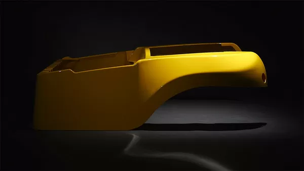
A large curved PC housing for medical and diagnostic equipment shows the typical female-mold brief: the visible outer surface carries custom cut-outs, mounting holes and reinforcement, and appearance is part of acceptance. Material and tooling decisions interlock here. ISO 75-2 specifies how the heat deflection temperature of plastics under load is measured, giving buyers a comparable HDT3 figure when a housing sits near heat sources; UL 94 classifies the flammability of plastic materials, and many formed equipment enclosures must meet a defined rating before release for electrical use.
When exterior texture must be especially crisp, pressure forming extends the female route by pushing the sheet against the cavity with air pressure above atmospheric. The comparison of vacuum forming and pressure forming explains when that added cost is justified.
Male vs Female Tooling: Side-by-Side Comparison
The table below condenses the differences buyers actually negotiate. These are tendencies shaped by draw depth, sheet gauge and material, not absolute rules — a shallow female part can behave like a drape over a male plug.
| Attribute | Male (Plug) Mold | Female (Cavity) Mold |
|---|---|---|
| Sheet side in contact | Inside surface of part | Outside surface of part |
| Sharpest detail | Inside geometry | Outside geometry, texture, lettering |
| Wall thickness behavior | Top of plug stays near sheet gauge; thinning down the sides | Rim and upper walls stretch first; deepest corners thinnest |
| Best suited to | Trays, liners, cell geometry, deep draws | Housings, enclosures, cosmetic exteriors |
| Draft strategy | Sized by shrinkage and draw depth on vertical plug walls | Inside free surface; texture depth adds draft demand |
| Venting focus | Top of plug, corners, detailed zones | Bottom corners, around exterior features |
| Typical tooling cost | Generally lower | Generally higher |
One practical note: whichever orientation is chosen, the cosmetic surface is the contact surface. If a drawing specifies texture on the outside and the quotation is based on a male tool, one of the two is wrong.
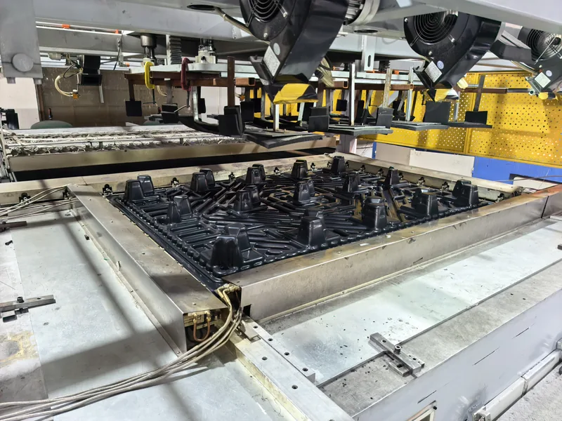
With 20+ vacuum forming and thermoforming machines and 45+ production lines across the plant, both male and female tooling can be trialled on production-class equipment, and prototyping runs alongside the same lines that will carry volume production. That makes an orientation trial a scheduling exercise rather than a compromise.
How Does Mold Choice Change Wall Thickness Distribution?
Mold orientation decides where the sheet touches down first, and touchdown order decides the thickness map. On a male mold the thickest zone is the top of the plug; on a female mold the thinnest zone is usually the deepest corner. Neither route produces a part at uniform sheet gauge.
As a working rule in heavy-gauge thermoforming, areas in direct contact with the tool retain the largest share of the starting gauge, while the first stretched zones can fall to roughly half of it on aggressive draws. The exact figure depends on material, sheet temperature and draw ratio4, so it belongs on a measured first article, not on an assumed drawing note. Specify a critical minimum thickness at named locations instead of quoting only the starting sheet size.
"Wall thickness in a formed part matches the starting sheet gauge."False
Forming always stretches the sheet somewhere, so thickness varies across every part. Assuming uniform gauge hides the thin corners that later crack under load or leak at a gasket, and the problem surfaces only after tooling is already cut.
"Thinning concentrates where the sheet stretches first and most."True
Contact zones keep close to the starting gauge while stretched zones thin, so the risk map follows the touchdown order. Naming a minimum thickness at loaded corners turns that physics into an inspectable requirement.
Verification is straightforward: cut the first article into a grid and measure wall thickness at marked points with an ultrasonic gauge or a micrometer, then compare the map against the functional requirement. Corners that carry load or seal a gasket deserve named minimums on the drawing.
Sheet is processed from 0.5 to 15 mm with a maximum forming length of about 2,500 mm, so large panels and deep enclosures stay within one forming envelope. Across spans that long, the difference between male and female thinning patterns is measured in whole millimetres, which is why the thickness map should be agreed before the tool is cut.
Which Details Should You Confirm Before Cutting the Tool?
Tooling quotations assume decisions that are cheap on paper and expensive in metal. Whichever orientation the part takes, lock these points with the molder first.
Draft and release: Male plugs need draft5 sized by material shrinkage and draw depth; the free surface shrinks away from the tool, but corners, texture and long vertical walls still lock. Female cavities need draft on the inside free surface, and any molded-in texture adds draft demand proportional to its depth.
Vent hole layout: Vents concentrate at the top of a plug and at the bottom corners of a cavity — wherever air is last to escape. Confirm diameter, count and whether vents will mark a cosmetic surface.
Corner radii and draw depth: Sharp internal corners thin locally and invite tearing; generous radii on both the tool and the part spread the stretch. Comparing part depth to its smallest opening early predicts thinning before any steel exists.
Trimming datum: The trimmed outline is programmed from the forming tool, so datum surfaces should be chosen while the orientation is still open rather than after first articles arrive.
Formed parts are finished on a 5-axis CNC trimming centre, and the trimmed outline follows the forming tool itself. Lock the datum surfaces early: once the tool exists, the trimming program inherits its geometry, and a late datum change means reworking both.
First articles close the loop, but a single good sample is not the same thing as a stable process.
"A passed first article proves the production process is stable."False
A first article samples one moment: one sheet lot, one oven condition, one operator setup. Sheet lot changes and oven zoning drift move wall thickness and dimensions between that sample and volume production, which is where disputes start.
"Stability is confirmed by tracking thickness and dimensions across production lots."True
Trending measurements over the first production lots exposes drift while it is still cheap to correct. It also gives both sides an agreed, measured basis for what acceptable parts look like.
FAQ
Can one part use both male and female forming?
Yes. Matched-mold forming presses the sheet between a male and a female pair, and twin-sheet forming uses two sheets and two tools to build hollow structural parts. Both variants raise tooling cost but control thickness on both surfaces.
Does a female mold always cost more than a male mold?
Usually, but not automatically. A finished cosmetic cavity needs deeper machining, polishing or texturing, which raises cost. A small shallow female tool can still cost less than a large male plug with dense venting, so compare quotations at identical scope.
How much draft does each mold type need?
Common practice starts around 1–3 degrees per side on smooth tools, with more on textured or deep vertical surfaces, but the right value depends on material shrinkage and draw depth. Treat draft as part of the part design, agreed with the molder, not a fixed number copied between projects.
Which mold type is better for a textured outside surface?
A female mold. Texture is machined or etched into the cavity and transfers directly to the part’s outer skin. A male mold puts the tool’s grain on the inside, which rarely suits visible parts.
Where should I go next on vacuum forming?
To keep digging into sheet selection, forming windows, tooling options and typical heavy-gauge parts, explore the vacuum forming process overview, or see how a vacuum forming manufacturer in China approaches tooling decisions end to end. Both cover the male-versus-female question inside full part development.
-
Vent hole: A small hole drilled through the mold surface that lets trapped air escape so vacuum can pull the sheet fully into every detail. ↩
-
Web: A wrinkle or fold of excess material that forms where the sheet bridges across a feature during forming, usually on the non-contact side. ↩
-
HDT: Heat deflection temperature, the temperature at which a plastic specimen deflects a defined amount under a specified flexural load. ↩
-
Draw ratio: The relationship between formed part depth and its smallest opening, used to estimate thinning and formability before tooling is made. ↩
-
Draft angle: The tapered offset from vertical built into mold walls so a formed part releases without scraping or distorting. ↩