Deep-draw parts rarely fail because the material was wrong. They fail because somewhere between the clamp frame and the deepest corner, the wall got thinner than the drawing allowed. Wall thickness reduction is the defining quality battle of heavy gauge thermoforming, and it is controllable once you understand where the sheet stretches and why. This article walks through the mechanics of thinning, the process levers that redistribute material, the measurement methods that verify the result, and the design decisions that prevent the problem before tooling is cut. For a broader view of the process family, start with our vacuum forming overview, then come back to the thickness details here.
- Thinning follows draw ratio: the deepest and farthest features lose the most wall.
- Even sheet heating does more for thickness uniformity than any other single process lever.
- Plug assist depth, vacuum sequencing, and forming temperature redistribute material into corners.
- Verify wall thickness with a written measurement plan at corners and high-draw zones, not at one convenient flat spot.
- Call out minimum wall at critical features instead of a single nominal value across the whole part.
- Most severe thinning is designed in; a DFM review before tooling costs far less than re-cutting a mold.
Why Does Wall Thickness Drop During Vacuum Forming?
Wall thickness drops because the heated sheet must stretch to cover surfaces that sit farther apart than the flat sheet did. Wherever the material travels the greatest distance from its clamped position, it stretches the most and finishes thinnest, so the thinning map is drawn by the geometry of the part itself.
Engineers describe this stretch with the draw ratio1, the formed surface area divided by the original projected sheet area. A shallow lid may see a draw ratio near 1.2:1 and lose perhaps 10 to 15% of its wall, while a deep enclosure can exceed 2.5:1 and lose more than half of its thickness at the corner. The loss is not a process defect; it is conservation of volume. The engineering question is whether the thinnest region still meets the structural, thermal, and sealing requirements of the part, and whether the loss repeats the same way cycle after cycle.
Which Zones Thin the Most on a Formed Part?
Deep corners, tall vertical walls, and any surface farthest from the clamp frame thin the most. On male tooling the top of the plug contacts and chills the sheet early, so the sidewalls below it stretch the remaining hot material and finish thinnest. On female tooling, the bottom corners of the cavity take the highest stretch.
Corner radius is the hidden multiplier. A tight radius forces the sheet to bend and slide over a small surface, concentrating stretch exactly where the wall is already losing material, while generous radii let the sheet drape instead of stretch. Webbing between tall close features is the visible symptom of the same imbalance. Reviewing part geometry against these zones before tooling — the logic behind our DFM checklist for heavy gauge thermoformed parts and molds — is the cheapest thinning correction available.

ZetarVac runs more than 20 vacuum forming machines and processes sheet from 0.5 to 15 mm with forming lengths up to about 2,500 mm. For thinning control, that envelope matters: a deep, large part can be planned against a real gauge range and a real forming area instead of being squeezed onto whatever machine happens to be free.
How Heat Distribution Controls the Thickness Profile
The sheet arrives at the mold carrying a temperature map, and that map decides where the material is willing to stretch. Hotter zones thin first; cooler zones resist drawing and pull material back toward themselves. A sheet that leaves the oven hotter on one edge will form with asymmetric thinning no matter how the vacuum is set, which is why zone-by-zone heater control is the first thing to review when a thickness profile drifts.
Watch the sag2 while the sheet heats. Moderate, even sag across the full sheet indicates a workable forming window; sag concentrated in one zone signals over-heating there, and that same zone will become the thinnest region of the finished part. Keep the working temperature a controlled distance below the point where the material loses stiffness: ISO 75-2 specifies the heat deflection temperature of plastics under flexural load, which gives you a defensible basis for judging how far a thinned, heat-exposed wall sits from softening in service.
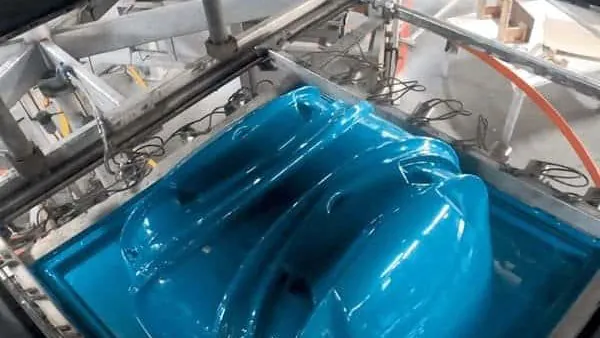
The practical routine is straightforward. Map the sheet temperature with a contact or infrared probe at defined points, balance the top and bottom heater banks, and lock the oven recipe into the process sheet. Our heavy gauge thermoforming guide covers machine and heater configurations in more depth.
"Cranking up the vacuum level is the best way to reduce thinning."False
Vacuum only pulls the sheet; it does not decide where the material goes. Stronger vacuum on an unevenly heated sheet stretches the hot zones faster, which can deepen corner thinning while adding chill marks on the formed surface.
"Even sheet heat is the primary lever for thickness uniformity."True
Right: balance the heater zones first, then tune vacuum timing. When the sheet enters the forming station with a uniform temperature map, material distributes where the geometry demands it instead of where the residual heat was sitting.
Can Plug Assist and Process Settings Reduce Thinning?
Yes. A plug assist pushes material into the deepest part of the cavity before vacuum pulls the sheet against the walls, pre-distributing thickness into the zones that would otherwise thin the most. Together with forming temperature and vacuum ramp timing, it is the strongest process-side correction available for deep draws.
Plug geometry and timing deserve real engineering attention rather than guesswork. Depth commonly lands around 60 to 80% of cavity depth: too shallow and the corners still starve, too deep and the plug tip chills the sheet locally or marks the surface. Plug material and temperature matter too, because a thermally controlled, low-stiction plug surface lets the sheet slide instead of freeze. On the vacuum side, a delayed or ramped vacuum on deep draws slows the final stretch into the corners and gives the material time to travel from the flange instead of tearing thin in place.
The ranges below are common engineering starting points, not guaranteed settings; the right values depend on the material, the sheet gauge, and the machine, and they must be confirmed on your own tooling.
| Process lever | What it controls | Typical starting range | Risk when overdone |
|---|---|---|---|
| Heater zone balance | Where the sheet stretches first | Even sag across the full sheet | Local overheat, sag, surface marks |
| Plug assist depth | Pre-distribution into deep zones | About 60–80% of cavity depth | Plug marks, local chill |
| Vacuum ramp rate | Stretch speed into corners | Slower ramp on deep draws | Chill lines, incomplete detail |
| Sheet temperature | Stretchability window | Near the upper safe forming limit | Degradation, sticking, sag |
| Starting sheet gauge | Margin over minimum wall | Roughly 20–50% above minimum | Cost, longer heat cycles |
Pressure forming — adding compressed air above the sheet alongside vacuum — earns its place on parts that need fine texture or sharp detail, and on moderate draws it helps press material into features vacuum alone cannot fill. For deep-draw thickness problems, however, plug assist and heat balance remain the primary corrections.
How Do You Verify Wall Thickness After Forming?
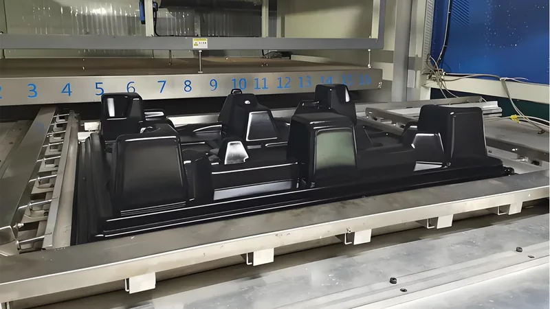
Measure thickness at the corners and other high-draw zones on a fixed grid, using ultrasonic gauges on trimmed parts and cut cross-sections for first-article validation. A single reading on a flat region tells you almost nothing about the risk the part actually carries.
A useful measurement plan lives on the drawing, not in someone’s memory. Define the critical points — the worst corner, the deepest sidewall, the sealing land — cut one first article through those points, and check the rest periodically with an ultrasonic gauge at the same coordinates.
Strength and compliance need validation too. ASTM D638 specifies the tensile test used on plastic sheet and formed-part coupons, so a coupon cut from the thinnest region confirms it still carries the load the flat-sheet data assumed. For formed equipment housings, UL 94 classifies the flammability of plastic materials and is required for many electrical enclosures3, and IEC 60529 defines the IP code that grades enclosure sealing against dust and water4 — both properties should be judged at the minimum formed wall, not the nominal.
Every formed part at ZetarVac is trimmed on a 5-axis CNC centre, and the trimmed outline follows the forming tool. Because the trim path references the formed surface, your measurement points at trimmed edges land on the same coordinates cycle after cycle, which is what makes wall-thickness trend data worth collecting.
That trend data is the difference between controlling thinning and discovering it. Track the corner readings across the run and against the first article; drift points back to heater balance or sheet lot changes long before the part fails a functional test.
"A passing first article proves wall thickness is stable in production."False
A first article is one cycle at one moment. Heater output drifts, sheet lots change, and ambient conditions move, so a part that measured well in the morning can drift out of limits by the afternoon without anyone noticing.
"Wall thickness needs a written measurement plan across the production run."True
Correct: define the measurement points, check them at first article and at a fixed sampling interval, and trend the results. Stability comes from monitoring and correction, not from a single approval at the start.
Should You Fix Thinning at the Design Stage Instead?
Yes — most severe thinning is designed in before the sheet is ever heated. Corner radii, draw depth, and draft angles fix the draw ratio; once the tool is cut, the process can only work inside the geometry that was approved.
Design for forming is mostly about giving the material somewhere to go. Use generous inside radii instead of knife corners, add draft on vertical walls so the sheet releases and stretches evenly, and avoid placing a deep section directly beside a shallow one, which forces the sheet to feed two demands at once. Where a solid deep wall is not structurally required, ribs or a stepped cross-section cut the local draw ratio dramatically. Every one of these choices shows up later as measurable wall thickness rather than as a rework conversation.
"A thicker starting sheet always fixes thin corners."False
The corner still carries the highest draw ratio, so added gauge raises the starting thickness while the percentage loss keeps following the geometry. You pay for material and cycle time, and the thinnest region can still land below the minimum you needed.
"Match the sheet gauge to the draw ratio and the part’s minimum wall."True
Correct: estimate the expected thinning from the geometry first, then choose a gauge that keeps the critical minimum after forming. That puts material exactly where the part needs it instead of paying for extra thickness everywhere.
When the geometry is right, gauge selection has room to work with instead of against you.
ZetarVac processes sheet from 0.5 to 15 mm with a maximum forming length of about 2,500 mm and supports prototyping, small batch, and large batch production. For a deep-draw project, that means thickness recovery can be tuned through gauge choice at any production volume, rather than forcing a redesign after the tool exists.
FAQ
How much wall thickness loss is normal in heavy gauge thermoforming?
Expect roughly 10 to 15% loss on shallow parts and 40 to 60% at deep corners on aggressive draws, driven mainly by draw ratio and material behavior. Treat those as planning ranges: measure your own geometry on a first article instead of assuming an average applies to your part.
Does the material choice change how much a wall thins?
Material sets the stretch window. ABS and PVC stretch broadly and forgive uneven heat; PC and PMMA have narrower windows that punish hot spots with local thinning; HDPE and PP sag heavily and demand tight heater zone control. Match the heater profile to the material you specified, not the other way around.
Should drawings specify nominal or minimum wall thickness?
Specify a minimum wall at critical features and a general nominal elsewhere. Because thinning is inherent to forming, a nominal-only callout makes nearly every deep-draw part technically out of specification. A minimum-wall callout at sealing lands, mounting bosses, and load paths reflects how the process actually behaves.
When is pressure forming worth considering for thickness control?
Pressure forming earns its cost on parts that need fine texture or sharp detail on shallow to moderate draws, because air pressure presses the sheet against the mold surface. For genuine deep-draw thickness problems, plug assist and heat balance do more than added pressure ever will.
What information helps a supplier control wall thickness on my part?
Share the drawing with minimum wall callouts, the material and grade, service temperature, and any sealing or load requirements. With that, an engineer can estimate the draw ratio, predict the thinning profile, and confirm whether the tooling concept can hold your critical minimum before cutting steel.
If you are evaluating suppliers for a heavy-gauge part, send your drawings to our vacuum forming engineering team or review our service scope and talk through your wall thickness targets before tooling is cut.
-
Draw ratio: The formed surface area divided by the original projected sheet area; a higher draw ratio means more stretch and therefore more thinning. ↩
-
Sag: The downward drooping of a heated sheet under gravity before forming; uneven sag signals an unbalanced sheet temperature profile. ↩
-
UL 94: The standard that classifies the flammability of plastic materials, commonly required for electrical equipment enclosures. ↩
-
IP code: The ingress protection rating defined by IEC 60529 that grades how well an enclosure seals against dust and water. ↩