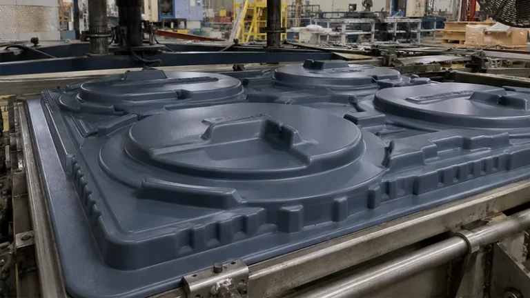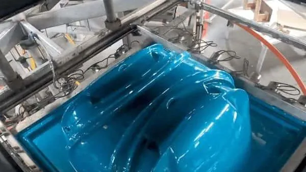

Vacuum holes are the smallest features on a thermoforming mold, and they quietly decide whether a part pulls clean or comes off the tool with thin corners, trapped-air blisters, and shiny dimples nobody ordered. Venting is not an afterthought; it is the mechanism that lets atmospheric pressure do the forming work. This guide covers hole sizing, placement, mark-off control, and verification for heavy-gauge vacuum forming, so you can review a mold drawing — or a failed first article — with a concrete checklist. If the terminology overlap confuses anyone on your team, our guide to the difference between thermoforming and vacuum forming clears it up in two minutes.
- Total open hole area — not the number of holes — controls how fast air escapes from the sheet-to-mold interface.
- Hole diameter should scale with sheet thickness: roughly 0.5–0.8 mm on thin gauges, up to 1.5–2 mm or slots on heavy-gauge sheet.
- Place holes where the sheet lands last: inside corners, deep pocket floors, boss bases, and flat webs between ribs.
- Mark-off on appearance surfaces is prevented at the mold — smaller holes, slots, or porous inserts — not polished out later.
- A leaking plenum or worn base gasket starves even a perfectly drilled hole pattern.
- Prototype hole layouts with plugged or re-drillable positions so a production tool can be corrected without starting over.
How Vacuum Holes Actually Work in Vacuum Forming
In vacuum forming, the driving force is atmospheric pressure pushing a heated sheet against a tool from which air has been removed. A typical shop vacuum level of −0.07 to −0.09 MPa leaves atmosphere to do the work; the holes themselves move almost no plastic, only air. Their job is to evacuate the air trapped between sheet and mold surface fast enough that the sheet contacts the tool while it is still inside its forming window.
That timing constraint is why material behavior matters. A heavy-gauge sheet stays formable for seconds, and its stiffness climbs steeply as it cools. Heat deflection data is a useful reference here: ISO 75-2 specifies how the heat deflection temperature of a plastic is measured under a defined flexural load1. A sheet preheated well into that range will follow fine mold detail; a cold sheet will bridge straight over carefully drilled corners no matter how many holes you add. For a wider view of the equipment and process options, our vacuum forming overview covers the full picture.
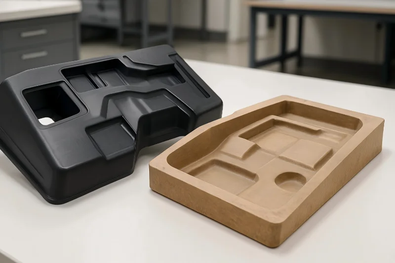
Two consequences follow. First, a hole only works where the sheet actually seals around it — a hole in an area the sheet bridges across vents the room, not the interface. Second, the hole pattern must be matched to a sealed plenum behind it, the cavity inside the tool that collects air from every hole and feeds the vacuum source2. Holes and plenum form one system, and most venting failures are plenum failures in disguise.
How Many Vacuum Holes Does a Mold Need?
As a starting rule for heavy-gauge work, size total open hole area at roughly 0.3–0.8% of the formed surface area and concentrate it where the sheet lands last. A 25–75 mm grid covers most tools, tightened to 15–25 mm in corners and deep pockets. Treat these as starting ranges: the right values depend on sheet gauge, material stiffness at forming temperature, and how quickly the machine can pull vacuum.
Hole diameter has to scale with sheet thickness. Thin sheet conforms quickly and needs only small holes; heavy-gauge sheet moves more air and stiffens faster, so undersized holes choke the draw. The table below gives common starting points:
| Sheet gauge | Typical hole diameter | Grid spacing | Notes |
|---|---|---|---|
| 0.5–2 mm | 0.5–0.8 mm | 25–40 mm | Pinholes suffice; keep off appearance faces |
| 2–6 mm | 0.8–1.5 mm | 40–60 mm | Standard medium-gauge pattern |
| 6–15 mm | 1.5–2 mm, or 1–2 mm slots | 50–80 mm | Slots on flat webs; tighten corners |
Note the slots. On broad flat webs — the panel between two ribs on a structural tray, for example — the sheet cools and wants to bridge, and holes alone may not evacuate the trapped pocket fast enough. Narrow slots vent more area per feature and leave less mark-off than an equivalent cluster of large holes.
"More vacuum holes always give faster and more even forming."False
Beyond a certain total open area, evacuation speed is limited by the plenum, the vacuum lines, and the pump — not by drilling more holes. Extra holes multiply mark-off risk, weaken thin mold ribs, and add machining cost without shortening the cycle.
"Total open hole area and a sealed plenum matter more than hole count."True
Cross-sectional area behind the holes is what determines evacuation speed. A tool with half the holes but a well-sealed plenum and correctly sized lines will out-form a densely drilled tool that leaks at its base gasket.
Where Should Vacuum Holes Be Placed?
Put vacuum holes where the sheet contacts the tool last: inside radii, deep pocket floors, boss bases, and the lower side walls of male tools. On female molds the bottom corners are the classic trap; on male molds, watch the base perimeter and every undercut region.
A dry-run contact check — draping paper or thin PVC over the tool and watching the contact order — tells you more at the concept stage than any simulation. On thick tools, drill holes from both faces so they meet cleanly; a blind hole that stops a millimetre short of the surface does nothing but collect debris. Bosses deserve special attention on structural parts: a 20 mm boss with no vent at its base will show a dimple or blister on nearly every cycle, and cut-out corners behave the same way.
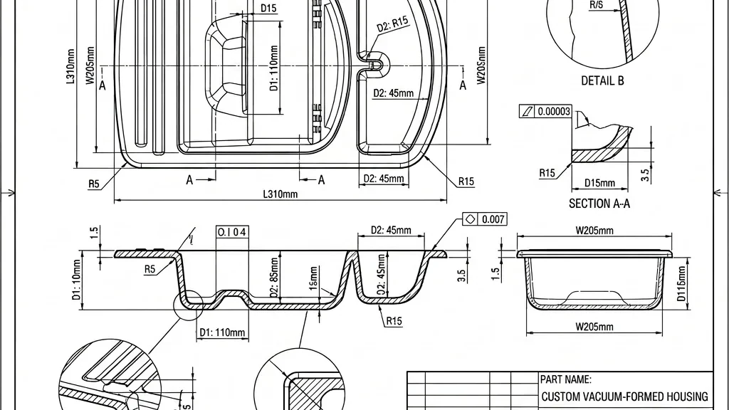
Our PC medical equipment housings are formed with custom cut-outs, mounting holes, and reinforcement — exactly the geometry where boss bases and corner radii trap air. On parts in this class, venting at every boss and cut-out corner is planned before the tool is cut, because reworking steel after first articles is the slow path.
Plan the release side too. The same holes that evacuate air during forming are commonly used in reverse to blow the cooled part off the tool with compressed air. Heavy-gauge parts grip hard as they shrink during cooling, so the pattern that formed the part must also release it; undercut regions need particular care, as covered in our guide to creating undercuts in a vacuum formed part.
What Hole Size Prevents Mark-Off Without Choking the Vacuum?
Keep vent holes below roughly 0.8 mm on cosmetic faces and prefer several small holes, a short slot, or a porous insert over one large opening. Mark-off scales with hole diameter and sheet temperature, so rigid high-temperature materials demand the smallest features.
Mark-off — the small shiny dimple where hot plastic is drawn slightly into a hole — is the price of venting on appearance surfaces3. Rigid sheet such as PC or PMMA forms hot and soft and prints hole geometry aggressively, so appearance tools for those materials run smaller holes at tighter spacing. Softer HDPE and PP forgive larger holes but bridge more readily, which pushes the design back toward denser coverage. Appearance is not the only constraint: for formed enclosures that must carry an ingress rating, IEC 60529 defines the IP code that classifies the degree of protection an enclosure provides against dust and water, so any hole crossing a sealing face needs a gasket-compatible design, not merely a small diameter.
"Vacuum hole marks can simply be polished out after forming."False
Polishing removes the sheen but not the geometry — a dimple is displaced material, not a stain. On heavy-gauge parts the distortion reaches several tenths of a millimetre into the wall and reads through paint and texture on every subsequent cycle.
"Prevent mark-off at the mold with hole size, slots, or porous inserts."True
Choosing the venting strategy per surface at the design stage costs a drafting review. Choosing it after first articles costs tool rework, surface refinishing, and a repeat of the whole qualification loop.
Venting Strategy for Deep Draws and Long Parts
Deep pockets and long tools introduce two problems a flat panel never sees. The first is volume: a deep draw traps a lot of air while the sheet is stiffening, so the last-formed corner needs dedicated venting rather than inheriting the general grid. The second is distance: on tools approaching our maximum forming length of about 2,500 mm, air travels a long way from the far corner back to the vacuum port, and a single feed point becomes a bottleneck. Long tools should have multiple plenum feeds so evacuation stays even across the part.
Plug-assist forming changes the picture again. The plug pushes sheet into the cavity before vacuum finishes the job, sealing off a large area as it goes. Vents in or around the plug zone — or slots along the plug path — stop air being compressed ahead of the plug, which otherwise shows up as a trapped-air blister at the bottom of the draw.
Where geometry makes drilled holes impractical — long narrow ribs, textured cosmetic faces — narrow slots, porous bronze or sintered inserts, and micro-perforated zones4 are the standard answers. Slots sit right against a rib root where a round hole would cut into the rib, and inserts can be cleaned or swapped without touching the tool body.
With more than 20 vacuum forming machines processing sheet from 0.5 to 15 mm, the same hole-design rules get applied across very different part families — thin PP trays at one end, thick PC and ABS housings at the other. That spread is why hole sizing is calculated per tool rather than drilled to a house standard.
How Do You Verify Venting Before Production?
Verify venting in two steps: a mold-level seal and evacuation test before forming, then a first-article review repeated over consecutive cycles at production settings. A single fully formed part proves little, because venting defects show up as cycle-to-cycle variation as the mold reaches steady-state temperature.
At the mold level, pull vacuum with the pump isolated and watch the decay; a fast pressure rise means a base gasket or plug leak that will starve the hole pattern no matter how well it is drilled. At the part level, map defects across ten or more consecutive cycles. The same corner failing every time points to a venting problem; defects that wander point to oven or sheet-temperature variation — and only the first group is fixed by re-drilling. Our DFM checklist for heavy-gauge thermoformed parts and molds folds these checks into a pre-tooling review.
"A fully formed first article proves the venting design is production-ready."False
One cycle can pass on generous preheat and a patient operator. Venting problems appear as variation: the corner that forms on run three but not run one, the dimple that emerges once the mold reaches steady-state temperature.
"Validate venting over consecutive cycles at production settings."True
Run at least ten parts at nominal oven and mold temperatures and compare defect maps across them. Consistent defects point to tool venting; drifting ones point to process setup, and only the first group is fixed by re-drilling.
FAQ
How deep should vacuum holes be drilled?
Through the mold surface and into the plenum. On tools thicker than about 30 mm, drill from both faces so the two bores meet cleanly; a hole that stops short of the forming surface is dead volume that collects debris.
Can vent holes be added to an existing mold after first articles?
Yes. Most aluminum and cast tools accept additional drilled holes or milled slots at problem areas, and that is the normal correction path after a first-article review. The cost is downtime plus re-polishing around the new features, which is why placement planning up front is cheaper.
Do vent holes affect the IP rating of a formed enclosure?
Only where they pass through a gasket land or sealing face. Venting is placed away from the gasket line, and the gasket design carries the ingress rating defined by IEC 60529.
What vacuum level should a thermoforming mold see?
Most heavy-gauge shops work between −0.07 and −0.09 MPa at the mold. What matters more than the pump rating is how fast that level arrives at the sheet interface, which depends on plenum volume, line diameter, and total hole area.
Are slots better than round holes for venting?
Narrow slots move more air per unit of surface disturbance and suit flat webs and rib roots. Round holes are easier to drill and plug, and they fit contoured surfaces where slot orientation would be awkward. Most tools use both.
If you are evaluating a new tool or debugging a stubborn first article, review your drawings with our team via the China vacuum forming manufacturer page, or send your venting and mold questions through our service overview — a short technical conversation at the design stage usually saves a re-cut later.
-
HDT (heat deflection temperature): The temperature at which a standard plastic specimen deflects a defined amount under a specified flexural load, measured per ISO 75-2. ↩
-
Plenum: The sealed cavity inside a thermoforming tool that collects air from all vacuum holes and channels it to the vacuum source. ↩
-
Mark-off: The small dimple or shiny spot on a formed part where hot sheet material has been drawn slightly into a vacuum hole or vent feature. ↩
-
Micro-perforation: A dense pattern of very small holes or a porous insert zone used to vent air from a mold surface without a single visible hole. ↩