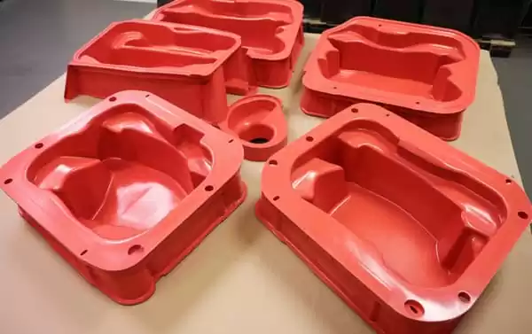
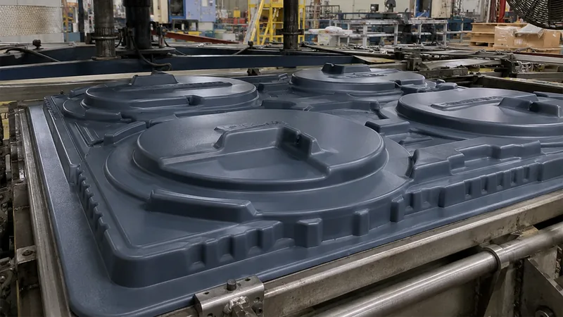
An undercut is what lets a vacuum formed cover snap onto a frame, a tray lock into a rack, or a housing grip its base without fasteners. It is also one of the features designers most often assume heavy-gauge thermoforming cannot do. In practice, undercuts are routine in thick-gauge work — provided they are engineered in from the start. This guide explains where undercuts come from, which creation strategies fit thick sheet, and how to validate them before production.
- An undercut is any geometry wider than its release path: snap beads, retention ridges, seal grooves, and inward flanges.
- There are three ways to create undercuts: form them with the tool, machine them after forming, or split the part and capture them through assembly.
- Flexible resins such as HDPE and TPE strip over formed undercuts readily; rigid ABS, PC, and PC/ABS need shallow geometry or post-form machining.
- Undercut depth must scale with sheet gauge, because thick sheet thins and springs back differently than thin stock.
- 5-axis CNC trimming can add precise undercuts after forming, which keeps the forming tool simple.
What Counts as an Undercut in a Vacuum Formed Part?
An undercut is any feature that is wider than the opening it must pass through when the part is pulled off the mold. Typical examples are snap-fit beads, retention ridges, grooves that hold seals, and inward-facing flanges on enclosure walls. If a straight pull cannot free the feature, it is an undercut.
In thermoforming the definition matters more than in molding, because the sheet is stretched over the tool rather than forced into it. A ridge formed against a male tool is only a true undercut if the part cannot be stripped over it at forming temperature; the same ridge on a flexible liner releases by elastic recovery alone. That distinction — stripped versus trapped — drives every decision that follows: tool style, draft, gauge, and whether the feature is formed or cut.
You will meet undercuts in equipment housings that snap onto bases, trays with retaining lips, machine guards that hook over frames, and covers with seal grooves around their perimeters. Each of those features has to survive two moments: demolding at forming temperature and engagement in the assembly at room temperature. A strategy that only handles one of the two fails in production.
Why Undercuts Are Harder in Heavy-Gauge Thermoforming
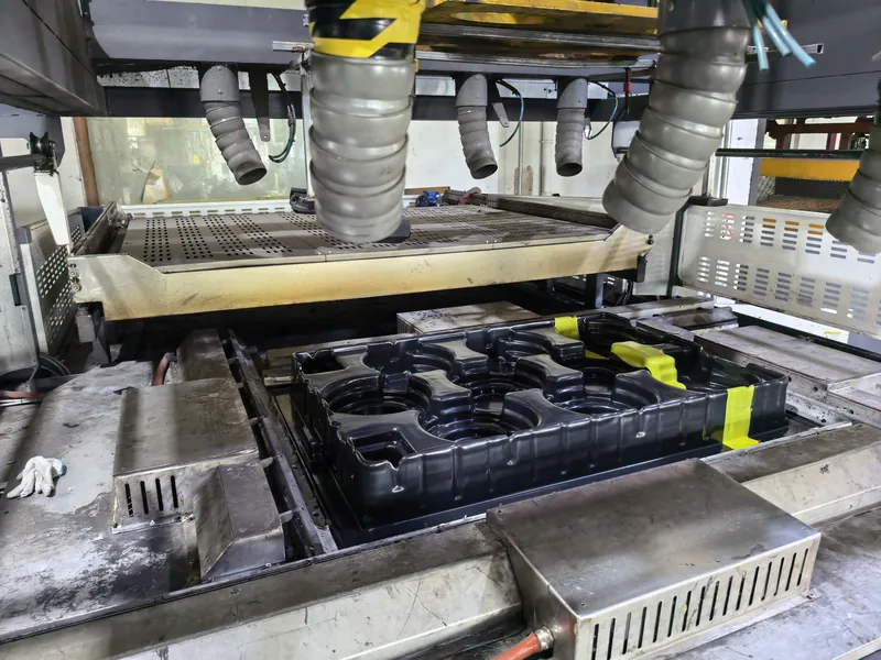
Thin-gauge packaging can rely on the elasticity of the web to pop over moderate undercuts. Heavy-gauge work cannot. Sheets in the 3–15 mm range have limited elongation at forming temperature, and stretched sidewalls thin as they draw, which reduces the material available for the feature to flex. When the part cools, its memory pulls the walls back toward the flat sheet, so an undercut that released easily hot can clamp onto the tool cold.
Tool style changes the problem. A male, or positive, tool forms against the inside of the part, and any bead formed against it must be stripped off — the tool physically traps the part. A female, or cavity, tool forms against the outside surface and lets the part shrink away from the walls as it cools, but the sheet thins as it draws down into the cavity, so detail near the bottom is where thinning concentrates. Draft1, corner radius, and undercut depth have to be chosen with that behavior in mind.
As a working range, rigid materials such as ABS and PC hold formed undercuts of roughly 0.25–0.5 mm without assistance when the geometry is radiused and the tool is drafted. Flexible materials — HDPE, LDPE, TPE — can carry formed undercuts of a millimetre or more. These are conventional starting points that depend on resin grade, sheet temperature, and part geometry, not guarantees, and they shift with thickness tolerance from lot to lot.
ZetarVac processes sheet from 0.5 to 15 mm and forms parts up to about 2,500 mm in length. That range is why undercut strategy is decided part by part: the same snap bead that releases cleanly from a 1 mm HDPE liner can lock a thick ABS enclosure onto its tool, and a long panel can bow enough between features to change how each one releases.
How Do You Create Undercuts in a Vacuum Formed Part?
There are three practical routes: form the undercut into the tool and strip the part over it, machine it after forming on a 5-axis trimming center, or split the part into two formed pieces that capture it through assembly. Flexible resins and shallow geometry favor the formed route, rigid materials and tight tolerances favor machining, and most production parts combine two of the three.
Form the undercut into the tool: Shallow beads, radiused ridges, and gentle retention lips are formed directly by the tool surface. The tool is drafted so the feature opens toward the pull direction, and the hot elasticity of the sheet carries the wall over the crest during demolding. Where more depth or sharper detail is required, a plug assist2 mechanically pushes the heated sheet ahead of the vacuum so the material over the feature stays thick enough to function. This route has the lowest piece cost because the feature is free once the tool exists — but its repeatability is only as good as the sheet thickness and temperature window the press actually runs.
Machine the undercut after forming: Grooves, snap beads, slots, and retention features cut into the formed part do not depend on how the sheet stretched. The undercut is positioned relative to the trimmed outline, which follows the forming tool, so the feature lands where the assembly needs it even when the formed wall has drifted slightly. For rigid ABS, PC, and PC/ABS parts — and for low and mid volumes where tool revisions would be slow — this is often the shortest path to a working undercut.
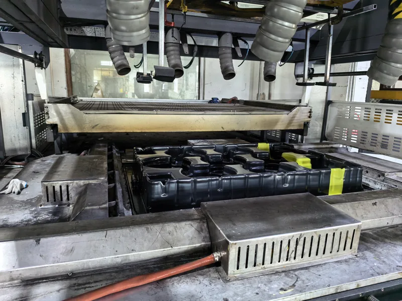
"Once an undercut is drawn in the 3D model, the forming tool will simply reproduce it."False
The sheet is stretched over the tool, not injected into it, so detail in deep draws thins or fills short. An undercut added in CAD without a release strategy can trap the part on the tool, and the fix late in a project is a tool revision rather than a file tweak.
"Every undercut needs a defined release strategy before tooling is cut."True
Decide early whether the feature will be stripped off a flexible wall, machined after forming, or captured by a second part. Each route imposes different rules on draft, radius, and gauge, and choosing the route first keeps the tool from being rebuilt around a feature it cannot release.
In practice the choice also shows up in the quotation. A tool that forms every undercut looks cheaper per part until the sheet lot changes, while a simpler tool with trimming time added per part stays predictable across the volume range.
Formed parts are trimmed on a 5-axis CNC center, and the trimmed outline follows the forming tool. For undercuts, that means a groove or snap bead can be machined relative to the same datum that positions the rest of the trim, keeping the feature aligned with mounting holes and mating edges.
Which Undercut Strategy Fits Your Material and Gauge?
Match the route to the resin and the gauge. Flexible sheet — HDPE, LDPE, TPE — strips over formed undercuts of a millimetre or more, while rigid sheet — ABS, PC, PC/ABS — keeps formed undercuts shallow and hands deeper features to post-form machining. The table below summarizes where each route wins.
| Route | Best fit | Typical working range | Main limitation |
|---|---|---|---|
| Formed undercut, male tool | Flexible resins, snap beads, liner lips | Shallow features to about 1 mm and beyond in PE and TPE | Traps the part; thick rigid sheet resists stripping |
| Formed undercut, female tool | Exterior ridges on enclosures and covers | Shallow features with generous radii | Sheet thins as it draws into the cavity |
| Machined undercut, 5-axis trimming | Rigid resins, precise grooves and beads | Any gauge, limited by the machined wall | Adds per-part trimming time |
| Two-piece assembly | Deep or internal undercuts | Any gauge the process can form | Adds a joining step and a second tool |
In heavy-gauge thermoforming, cost follows the route, not the feature itself. A formed undercut is nearly free at the press but constrained by material behavior, while a machined undercut is paid for in cycle time but almost unconstrained in geometry. Two-piece assemblies trade tooling simplicity for a joining operation, which matters when the enclosure also carries sealing or stiffness targets.
"A formed undercut in thick rigid sheet behaves like the same undercut in thin flexible sheet."False
Elongation and spring-back do not scale with thickness — they get worse. Thick rigid walls thin more at the draw, recover harder toward the flat sheet, and can lock onto the tool cold. What strips in 1 mm HDPE can require a redesign in 8 mm ABS.
"Undercut depth is chosen against sheet gauge and resin, not the CAD model alone."True
A practical review asks three questions before tooling: how much the wall thins at the feature, how much elastic recovery the resin shows at demolding temperature, and what happens if the sheet runs at the low end of its thickness tolerance. Answering those turns an undercut into a specified feature instead of a hope.
How Do You Validate an Undercut Before Production?
Treat the undercut as a functional feature with a written acceptance check: the part must release from the tool at forming temperature, and the feature must engage and release at room temperature without whitening, cracking, or loss of retention. Verify release at the press, measure the feature against the drawing, and base strength judgments on the actual sheet lot.
ASTM D6383 defines the tensile test method used to qualify plastic sheet and formed parts, and it is the reference behind the yield strength and elongation values that decide whether a snap bead can strain over its mating feature without stress cracking. Because forming thins and orients the wall, values measured on formed sheet from the production lot are more trustworthy than datasheet figures for the raw resin.
Where the formed part is an enclosure, the undercut often sits next to requirements that are not mechanical at all. UL 944 classifies the flammability of plastic materials and is commonly specified for equipment housings and covers, while IEC 605295 defines the ingress protection ratings that an IP-rated formed cover is sold against. A retention bead that passes release testing but compromises the gasket path of a sealed cover has failed the assembly, not just the feature.
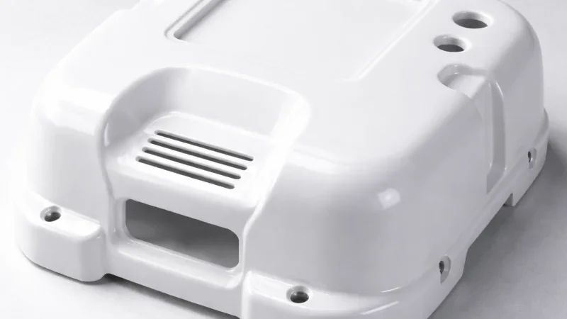
The material library behind these parts runs from ABS, PC/ABS, HDPE, and PP for housings, trays, and structural work to TPE and TPU for soft, flexible features. That breadth matters for undercuts because the strategy can start from the resin the application needs — a flexible TPE lip can be formed where a rigid PC bead would have to be machined.
One more check belongs in every trial plan: release behavior is a process observation, not a formality.
"A first article that releases cleanly proves the undercut is production-ready."False
One release event proves one sheet at one temperature on one day. Production varies in sheet thickness tolerance, oven zone balance, and ambient conditions, and an undercut near its stripping limit is exactly where that variation appears as parts that hang up on the tool or beads that relax out of spec.
"Undercut release should be checked across the production window, not just on the first shot."True
Run the release check at the start and end of a forming session, with sheet from more than one lot where possible, and record demolding behavior alongside part measurements. A feature that releases with margin across those conditions will survive a full production run.
FAQ
How much draft angle does a vacuum formed part need around an undercut?
Formed undercuts work best when the walls leading into them carry at least 1–3 degrees of draft, with the higher end on male tools and thick rigid sheet. Draft does not remove the undercut; it determines whether the sheet can ride over the crest during demolding instead of hanging on it.
Can deep undercuts be formed directly into thick-gauge sheet?
Rarely for rigid resins. In ABS, PC, and PC/ABS above a few millimetres, formed undercuts beyond roughly half a millimetre are unreliable, so deeper features are cut by 5-axis machining after forming or captured by a two-piece design. Flexible resins are the exception and can form deeper retention features directly.
Does adding an undercut increase tooling cost?
A formed undercut usually does not, because the feature is part of the tool surface itself. Cost rises when the undercut forces a more complex tool, a plug assist, or a post-forming machining operation. Those additions are usually still cheaper than redesigning the assembly to avoid the feature.
Can undercuts be added to an existing formed part design?
Often, yes. Because machined undercuts are cut after forming, they can be introduced or revised without rebuilding the forming tool, which makes them a practical way to add a snap or retention feature during a design iteration. Formed undercuts, in contrast, are locked in when the tool is cut. For related geometry questions, see this guide to creating a seamless vacuum formed part.
Which materials hold formed undercuts best?
Flexible and semi-rigid grades lead: HDPE, LDPE, PP, and TPE strip over formed undercuts readily. Rigid engineering grades — ABS, PC, PC/ABS — hold only shallow formed undercuts but machine cleanly, so the undercut can be cut precisely after forming. The right choice follows the enclosure, tray, or guard the feature has to serve.
To keep exploring how heavy-gauge thermoforming handles features like undercuts, review the vacuum forming process overview, or walk through what a China-based vacuum forming manufacturer offers for enclosures, trays, and structural formed parts.
-
Draft angle: The tapered wall built into a part or tool so it can release from the mold; on vacuum formed parts it commonly runs from about 1 degree on female features to 2–3 degrees or more on male cores. ↩
-
Plug assist: A helper plug that mechanically pushes the heated sheet into the tool before vacuum is applied, used to improve wall distribution and form deeper detail. ↩
-
ASTM D638: The standard tensile test method for plastics, used to qualify sheet stock and formed parts. ↩
-
UL 94: The flammability classification standard for plastic materials, frequently required for equipment enclosures. ↩
-
IP code: The ingress protection rating system defined by IEC 60529 for electrical enclosures. ↩