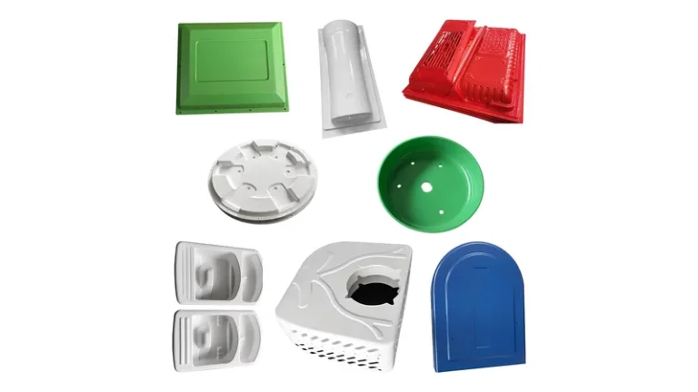
Choosing between vacuum forming and injection molding is one of the first process decisions in any plastics development project, and it is also one of the most commonly misjudged. The two processes share many polymers and often serve the same product families, yet they differ fundamentally in tooling, part size, wall thickness, tolerances, and cost structure. This guide compares them the way a manufacturing engineer would: process physics first, then tooling economics, then the properties and dimensions you should actually specify before release. The aim is not to crown a universal winner but to show which factors—size, volume, gauge, and compliance requirements—decide the outcome for your specific part.
- Vacuum forming uses single-sided tooling that costs a fraction of a matched injection mold and can be cut in days rather than weeks.
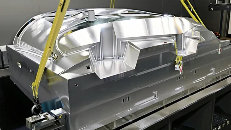
- Forming wins on part size: heavy-gauge sheet from 0.5 to 15 mm and forming lengths up to about 2,500 mm allow very large enclosures in one piece.
- Injection molding holds tighter, more repeatable tolerances because both part faces are defined by matched steel; formed parts rely on tool-side geometry plus CNC trimming.
- Per-part economics favor molding at high volume, while forming stays competitive from prototypes through roughly the low tens of thousands of units, depending on part size.
- Both processes run similar materials—ABS, PC, PC/ABS, PP, HDPE—but formed parts must be validated on the finished part, not just the sheet data.
- The decision usually comes down to annual volume and part footprint, not to perceived part quality.
What Is the Core Difference Between the Two Processes?
Vacuum forming shapes a heated plastic sheet over a single-sided mold using vacuum, while injection molding forces molten polymer into a closed, two-sided mold under high pack pressure. Forming starts from sheet stock at low forming pressure; molding starts from melted pellets at pressures of roughly 70–200 MPa. Tooling cost, size limits, surface finish, and tolerance behavior all follow from that one difference.
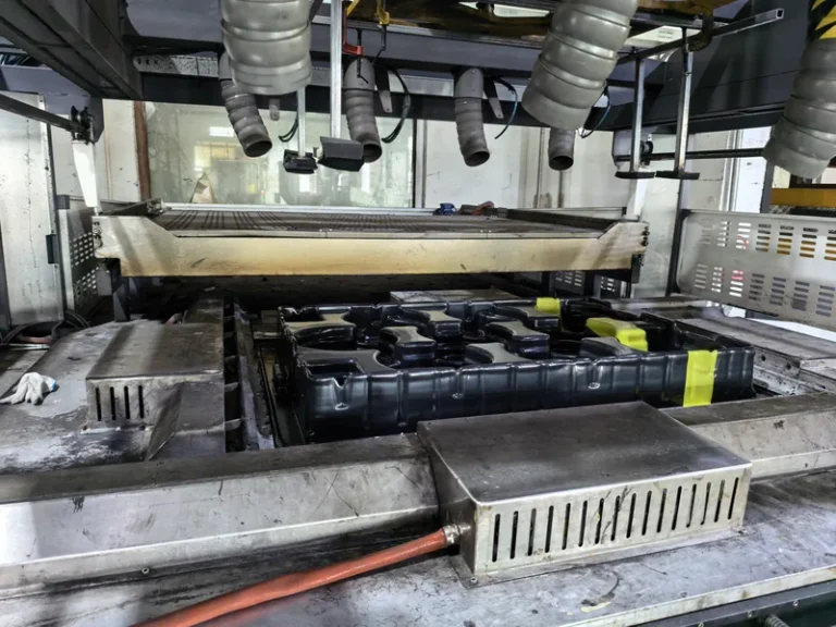
Because thermoforming works on sheet rather than melt, the polymer sees far less shear and never passes through a runner system. The sheet is clamped, heated into its forming window—commonly well above its softening point, depending on the material—and drawn against the tool by vacuum. In heavy gauge work, pre-stretching the sheet with a bubble or plug helps distribute material before the vacuum pulls it into final geometry. The result is a part with one tool-defined face and one free face. The sheet heating and forming stages are described step by step in this overview of how vacuum forming works.
Thickness distribution is the engineering consequence. As the sheet stretches it thins most where the draw is deepest, and the amount of thinning scales with the draw ratio1. Corners and deep pockets therefore need generous radii, and wall gauge must be engineered rather than assumed. This is not a defect to eliminate but a design input to manage: the designer sets the starting sheet gauge so the thinnest formed section still meets the structural requirement.

Where Does Each Process Win on Cost and Volume?
Thermoforming wins on tooling cost and lead time; injection molding wins on per-part price at high volume. As a rough screen, forming stays cost-competitive from prototypes up to roughly 1,000–10,000 annual units, while molding amortizes its tooling above that range. The larger the part, the further the crossover shifts in favor of forming.
| Decision factor | Vacuum forming (heavy gauge) | Injection molding |
|---|---|---|
| Tooling cost | Low; single-sided mold in cast or machined aluminum | High; matched steel mold with cooling and ejection systems |
| Tooling lead time | Days to a few weeks | Typically 6–16 weeks |
| Maximum part size | Sheet 0.5–15 mm; forming length up to about 2,500 mm | Limited by clamp tonnage and platen size |
| Wall thickness | Starting sheet 0.5–15 mm; formed gauge set by draw depth | Usually 1–4 mm for cost efficiency |
| Cycle time per part | Minutes, including heating and trimming | Seconds to tens of seconds |
| Typical economic volume | About 250–10,000+ units per year | Thousands to millions of units |
| Surface detail | One tool-textured face; free face keeps the sheet surface | Both faces molded with crisp detail |
| Design changes | Fast, low-cost tool modifications | Costly rework or new inserts |
Two numbers usually settle the argument. The first is tooling amortization: a matched injection mold can cost several times a forming tool, so the molding route must sell enough parts for that gap to close. The second is cycle time: molded parts emerge in seconds, formed parts in minutes once heating, forming, and trimming are counted. Every real project sits somewhere between those two forces.
"A vacuum formed part is always weaker than an injection molded part."False
Sheet gauge decides this, not the process name. A 5–8 mm formed panel in ABS or PC often outstiffens a 2–3 mm molded wall because flexural stiffness rises with the cube of thickness, which ASTM D790 measures directly. Accepting the claim unchecked leads engineers to discard forming for exactly the large structural panels where it performs best.
"On large shallow parts, heavy-gauge forming can match or beat molded stiffness."True
Stiffness scales with the cube of wall thickness, and heavy-gauge thermoforming routinely delivers 4–10 mm walls on large panels. A molded part of the same outer size would need high-tonnage tooling to reach a similar section. Validate the specific grade with flexural testing, then build flanges and stiffening geometry into the formed sheet.
Volume forecasts also deserve skepticism on both sides. Program volumes shift, geometries get revised, and a tool that is cheap to modify protects the business case in ways a hardened steel mold cannot. When a program is early or the design may still move, forming is often the cheaper route to a correct part in the field.
ZetarVac runs 20+ vacuum forming machines within a plant of 45+ production lines and supports prototyping, small batch, and large batch production, with reference monthly capacity of about 100,000–200,000 pieces. A program can therefore start on a prototype forming tool and scale into series production without changing process or supplier.
How Do Part Size and Wall Thickness Compare?
Heavy-gauge forming is the practical route for large parts: sheet from 0.5 to 15 mm can be processed with forming lengths up to about 2,500 mm, so an equipment enclosure can be produced as a single piece. Injection molding machine tonnage scales with projected area, which makes large parts expensive. Beyond roughly half a square meter, forming is usually the only economical option.
Large parts are where the two processes diverge most sharply. A molded enclosure of one square meter may demand thousands of tonnes of clamping force and a mold that dominates the project budget. A formed enclosure of the same footprint needs a larger oven and a bigger trimming envelope, both of which scale far more gently. This is why machine guards, equipment housings, and large vehicle components are almost always formed.
Wall thickness follows the same logic. Molded walls are usually kept near 1–4 mm because thick sections slow the cycle and invite sink marks. Heavy gauge forming starts from solid sheet in gauges from 0.5 up to 15 mm, so the formed wall is engineered by choosing the starting sheet and managing draw thinning, with cooling governed by the tool and the sheet itself. Structural panels, industrial trays, and equipment liners exploit this directly.
"A passed first article means every later part will hold the same tolerances."False
A first article only proves that the tool, the sheet lot, and the cycle settings worked together on that day. Heater drift, new sheet lots, and ambient changes shift free-surface geometry over a run, so late-batch disputes between buyers and suppliers usually trace back to this assumption.
"Long-run dimensional stability comes from controlling the sheet, not just the tool."True
Formed part geometry depends on sheet gauge, lot, and heating profile as much as on the mold itself. Specify incoming sheet properties, lock the heating cycle, and re-measure trimmed outlines periodically. That discipline keeps tolerances stable for the life of the program.
For buyers, the practical takeaway is to state critical gauge zones on the drawing. If a mounting boss must retain a minimum wall, say so with a number, and confirm it on a formed sample rather than on the sheet certificate. The process can hit that target with the right starting gauge; it simply has to be asked for.
Which Material Properties Should You Validate Before Release?
Test the formed part, not just the data sheet. ASTM D638 specifies the tensile test method used to validate both the incoming thermoformable sheet and the finished formed part, and ISO 75-2 defines the heat deflection temperature2 that predicts how a panel behaves under load near its service temperature. For electrical housings, add UL 943 flammability data and the IEC 60529 ingress protection rating4 where sealing matters.
Forming adds one variable molding does not have: molecular orientation. Stretching the sheet aligns polymer chains along the draw direction, so tensile strength and elongation can differ between the draw direction and the cross direction. Cut ISO 527-2 tensile specimens from both directions of a formed panel and use the lower values for structural calculations. The effect is modest on heavy-gauge parts with shallow draw but real on deep-draw geometries.
Material selection is largely process-neutral—ABS for housings and guards, PC and PC/ABS for impact resistance, HDPE and PP for industrial trays and liners, PMMA for clear covers, ASA for outdoor exposure—because nearly every molding-grade resin has a formable sheet equivalent. The properties that differ are the ones the forming cycle creates: directional strength from orientation, tool-side surface texture, and the local gauge distribution described above.

ZetarVac forms ABS, PC, PC/ABS, HDPE, LDPE, PP, PMMA, ASA, PA6/PA66, POM, TPE, TPU, TPV, and PP/GF sheet in gauges from 0.5 to 15 mm. A part designed around a molding-grade resin almost always has a directly formable sheet equivalent, so material choice rarely forces the process decision.
How Do Tolerances and Surface Finish Differ?
Injection molding holds tighter, more repeatable tolerances because both faces of the part are defined by matched tool steel. Vacuum forming defines one face by the tool and lets the free face follow sheet sag and gauge variation, so tolerances on that side are inherently looser. The trimmed outline itself, however, can be held precisely with CNC trimming.
As a broad engineering guide, a formed part holds tool-side features on a medium-sized housing to within roughly a millimetre, with more movement on free surfaces and deep draws, while comparable molded features hold tolerances several times tighter. Treat those as screening figures only: quote tolerances per feature against part size, gauge, and draw depth, and confirm them on measured samples rather than a generic table.
Surface finish splits down the middle. The tool side of a formed part carries whatever texture the mold carries, and pressure forming—applying air pressure above the vacuum—sharpens detail and texture transfer further. The free side keeps the original mill finish of the sheet, which is visually different and may show more markings. Cosmetic parts should therefore specify which face is visible and select sheet surface and tool texture accordingly.

Every formed part at ZetarVac is trimmed on a 5-axis CNC centre, so the trimmed outline follows the forming tool rather than a hand-held template. Cut-outs, mounting holes, and edge profiles stay consistent from the first article through the last piece of the batch.
FAQ
Which process is cheaper for a first production run?
Vacuum forming is almost always cheaper to start, because a single-sided forming tool costs a fraction of a matched injection mold and takes days instead of weeks to produce. For pilot builds, field trials, and low-volume production, forming reaches the first saleable part with far less committed capital. Molding becomes the cheaper route only once volume amortizes its tooling.
Can thermoformed parts be as strong as molded parts?
Yes, when the design uses heavy-gauge sheet. A 5–8 mm formed panel in ABS, PC, or HDPE can exceed the stiffness of a typical 2–3 mm molded wall, because flexural stiffness rises with the cube of thickness. Validate the specific grade on formed specimens using ASTM D638 tensile and ASTM D790 flexural testing, then design to the measured values.
What tolerance can vacuum forming hold?
It depends on part size, gauge, and draw depth, so tolerances should be quoted per feature. Tool-side dimensions and CNC-trimmed outlines hold well; free-surface contours move more between sheet lots and heating conditions. Treat formed parts like sheet-metal parts: define datum faces, mark which dimensions are tool-controlled, and measure the rest on first articles and periodically in production.
Does heavy-gauge forming work for thick-walled industrial parts?
That is precisely its home territory. Sheet up to 15 mm thick and forming lengths up to about 2,500 mm support structural panels, equipment liners, machine housings, and material-handling trays in one piece. Thick formed sections also cool from a solid sheet rather than a pressurized melt, avoiding the sink marks and long packing cycles that thick molded walls require.
How should I pressure-test the decision on my own part?
Start with three numbers: annual volume, part footprint, and the thinnest wall your structure allows. If volume sits below the low tens of thousands or the part is large, put forming on the shortlist and compare quoted tooling side by side. To keep researching, explore the ZetarVac vacuum forming hub, review the full manufacturing service scope, and compare the forming-versus-molding decision in more detail before shortlisting suppliers.
-
Draw ratio: the ratio of formed part surface area to original sheet area; higher draw ratios mean more thinning during forming. ↩
-
HDT: heat deflection temperature, the temperature at which a standard bar deflects a set amount under flexural load, measured per ISO 75-2 or ASTM D648. ↩
-
UL 94: the flammability classification standard for plastic materials, with ratings such as V-0, V-1, and V-2 commonly specified for equipment enclosures. ↩
-
IP code: the ingress protection rating defined by IEC 60529, classifying enclosure sealing against dust and water. ↩