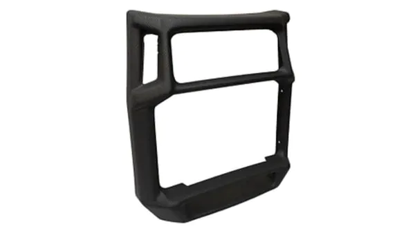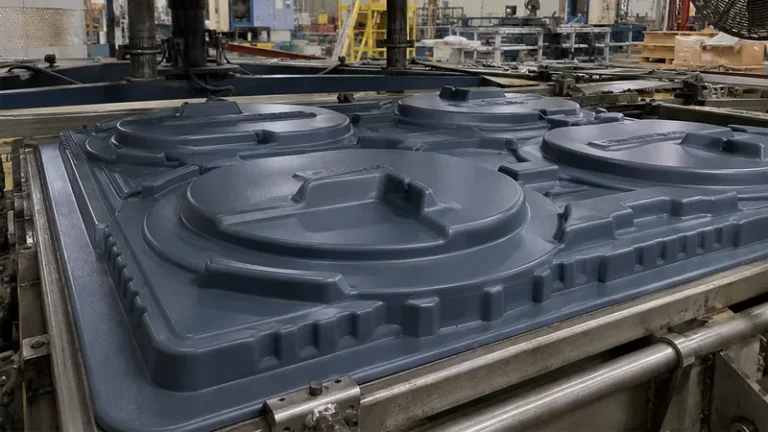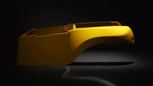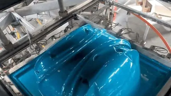
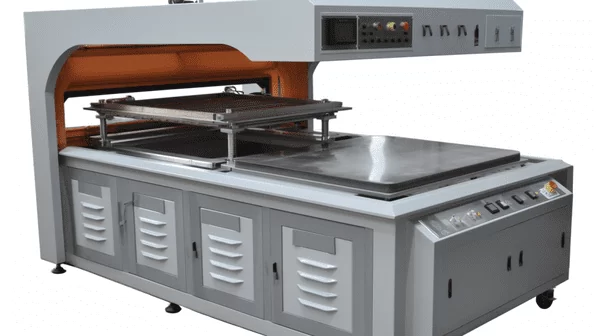
Vacuum forming answers a specific engineering problem: how to turn a flat thermoplastic sheet into a large, repeatable three-dimensional part without machining it from solid or joining pieces together. From machine guards and equipment housings to agricultural trays and medical enclosures, the process shapes heated sheet over a single mold using little more than atmospheric pressure. This guide walks through the mechanics stage by stage, the parameters that decide part quality, the materials that suit heavy gauge work, and the checks that separate a reliable formed part from a troublesome one.
- Vacuum forming works by clamping a plastic sheet, heating it to forming temperature, sealing it over a mold, drawing vacuum so atmospheric pressure presses the sheet into shape, then cooling and trimming.
- Heavy gauge thermoforming processes sheet from roughly 0.5 to 15 mm, far thicker than packaging film, which changes heating, cooling and tooling decisions.
- Heat input and cooling control wall thickness distribution more than vacuum level does; vacuum tops out at one atmosphere, so it is a fixed tool rather than a tuning knob.
- Mold design — draft angles, corner radii, vacuum hole layout and mold material — sets both formability and cycle time before the first sheet is heated.
- Most first-article rejections trace back to four failure modes: thin corners, webbing, surface mark-off and post-forming warpage.
- Material selection across ABS, PC, HDPE, PP and PMMA drives forming temperature, process window and end-use compliance such as flammability ratings.
What Is Vacuum Forming and Where Does It Fit?
Vacuum forming is a thermoforming process that shapes a heated thermoplastic sheet over a mold by drawing the air out between sheet and mold surface, so atmospheric pressure presses the sheet into its final geometry. Once the part cools, the formed shell is trimmed to finished dimensions. It is the standard route for large parts — enclosures, trays, guards and housings — where part size or production volume makes other molding methods uneconomical.
The term covers a family of related techniques. In vacuum forming, a vacuum of roughly 0.07–0.09 MPa does the forming work, which caps forming pressure near one atmosphere; pressure forming adds compressed air above the sheet for sharper texture and detail. Both belong to thermoforming and share the same core mechanics of a clamped sheet, controlled heat, one mold surface and a defined cooling stage. Industry references such as the SPE Thermoforming Division catalogue how these variants split by sheet gauge, tooling type and end market, which is a useful benchmark when comparing supplier proposals.
Heavy gauge work is what most industrial and equipment buyers mean by vacuum forming. Sheet from under a millimetre to 15 mm behaves very differently: thick sheet needs two-sided heating and long soak times, while thin film forms in seconds. The dividing line changes everything downstream — heater power, clamp design, cycle time and the achievable draw ratio1 of the part. For a lighter companion overview of the same cycle, see the site’s guide to how plastic vacuum forming works.
How Does the Vacuum Forming Process Work Step by Step?
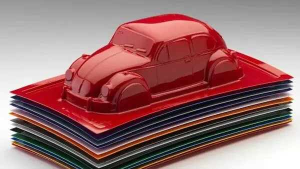
The cycle has six stages: load and clamp the sheet, heat it to forming temperature, pre-stretch and seal, apply vacuum so atmospheric pressure drives the sheet onto the mold, cool below the heat deflection temperature2, then release and trim. On industrial machines a full cycle runs from a couple of minutes for thin gauge to twenty minutes or more for thick structural sheet.
Step 1: Loading and clamping. The sheet is locked into a clamp frame that seals its edges. Frame pressure must hold the sheet flat as it softens and sags; a slipping edge lets the sheet shrink sideways during heating and ruins registration. On double-end machines the frame shuttles the heated sheet to the mold station while the next sheet heats, which is where most cycle-time savings live.
Step 2: Heating. Infrared heater banks bring the sheet into its forming window, where the material stretches rubbery without tearing. As working ranges, amorphous sheet such as ABS and PC typically forms in the 120–190 °C region while polyolefins run in a narrower, lower band; exact settings depend on grade, gauge and heater type. Thick sheet is heated from both sides so the core reaches temperature without the skins degrading. Operators watch sheet sag as a live indicator — sag that stops increasing usually means the core is up to temperature.
Step 3: Pre-stretch and sealing. For deep draws, a billow pre-stretch puffs the softened sheet upward before it touches the mold, redistributing material toward zones that would otherwise thin out. The sheet edge then seals against the mold rim, isolating the cavity for vacuum.
Step 4: Applying vacuum. Small holes and channels in the mold surface let the vacuum pump evacuate the sealed cavity in one to two seconds. Because vacuum cannot exceed atmospheric pressure, this is a fixed-force event: the engineering levers are hole placement, evacuation speed and how much material the pre-stretch has already positioned.
Step 5: Cooling. The part must cool below its heat deflection temperature before release, or it distorts on the bench. Fans, water-cooled mold surfaces or mist pull heat out, and thick sections need proportionally longer because plastic conducts heat slowly. Cooling is usually the largest single block of the cycle.
Step 6: Release and trim. The formed shell comes off the mold and moves to trimming, where 5-axis CNC routers cut the final outline, windows and mounting holes.
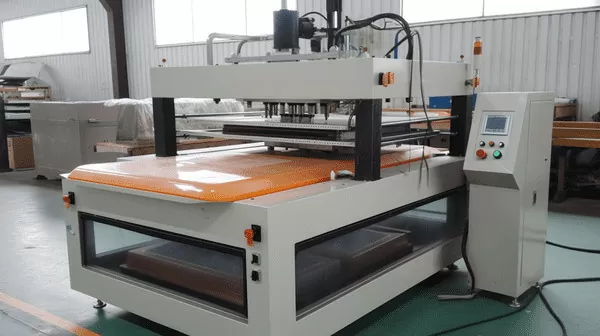
ZetarVac runs more than 20 vacuum forming machines processing sheet from 0.5 to 15 mm with a maximum forming length of about 2,500 mm. For a project, that means long panels and equipment enclosures several metres across can be formed as one shell instead of being split into sections and joined.
Every stage has a quantifiable setting — heater zone temperatures, soak time, evacuation duration, mold temperature, cool time — and those settings, not the vacuum level, are what a capable molder tunes during process qualification. Tooling, forming and trimming can be split across vendors or kept under one roof; ZetarVac’s service overview shows how an integrated workflow ties mold making, forming and finishing to a single process owner.
"Once the first article passes inspection, the process is stable for the rest of the run."False
A first article only proves the tool geometry and the settings used that day. Sheet lots, heater calibration drift and ambient changes move the process afterwards, so a passing sample does not protect later batches from thin corners or warpage.
"Stability comes from controlling heat, time and cooling, not from one approved sample."True
A process is production-ready when its windows are documented and repeatable: heater profiles, soak times, cool times and trim datums recorded and re-checked per lot. That documentation is what keeps part number 5,000 within the same limits as part number one.
What Role Does the Mold Play in Part Quality?
The mold sets wall thickness distribution, cycle time and surface finish before the first sheet is ever heated. Draft angles, corner radii, vacuum hole layout and mold material each trade formability against tooling cost, so decisions made at the tooling stage define part quality for the entire production run.
The first choice is male versus female tooling. A male, positive mold thins the top of the part as material bridges over the mold first, while a female cavity thins the outside corners. For an equipment housing with visible interior surfaces, that difference decides which face shows forming texture and which stays smooth.
Draft angles of 1–3 degrees are the practical minimum, with more allowance for deep draws and textured surfaces that grip the mold. Corner radii should be at least equal to sheet thickness, because sharp internal corners concentrate thinning and start cracks under impact. Vacuum holes typically run 0.4–1.5 mm in diameter — small enough to leave no mark — patterned densely at deep corners and tall features where the sheet lands last.
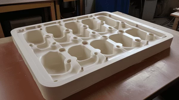
Mold material follows volume. Wood and resin molds suit prototype quantities and design iteration; cast or machined aluminium carries production duty, holds temperature through water channels for faster cycles, and preserves surface texture for years of service. For parts where the trimmed outline must follow the forming tool exactly, the mold and trim fixture are engineered as one system, which is how 5-axis trimming of formed parts holds repeatability lot after lot.
"Vacuum formed parts hold machined-level tolerances across the entire surface."False
Formed surfaces shrink and spring back as they cool, and the variation depends on material, gauge and draw depth. Dimensioning a free-formed wall to a machined-grade band either fails inspection or forces expensive hand correction.
"Tight tolerances belong on trimmed edges and machined features, not on formed surfaces."True
Experienced drawings profile formed walls with generous bands and put critical dimensions on the 5-axis trimmed outline, drilled holes and mounting bosses. That split respects how the process actually behaves and keeps inspection predictable.
Which Materials Suit Heavy-Gauge Thermoforming?
Materials with a wide forming window and stable melt strength work best. Amorphous plastics such as ABS, PC and PMMA soften across a broad temperature range, which makes them forgiving on deep draws, while semi-crystalline sheet such as HDPE and PP forms in a narrower window and needs tighter heat control.
| Material | Typical formed applications | What to plan around |
|---|---|---|
| ABS | Equipment housings, automotive interior parts, cases and guards | Wide forming window, good detail; heat evenly to avoid surface marking |
| PC | Clear guards, equipment protection covers, automotive parts | High forming temperature; dry the sheet first to avoid bubbles |
| HDPE | Industrial trays, equipment liners, storage boxes | Higher shrinkage; design generous draft and expect warpage control work |
| PP | Trays, boxes, automotive interior parts | Narrow forming window; needs tight heater zone control |
| PMMA | Clear covers, luminaires, display parts | Excellent clarity; brittle when cold, so trim and handle parts warm |
| PC/ABS | Automotive interiors, equipment housings | Blends PC toughness with ABS formability |
| TPE | Soft liners, seals | Low stiffness; often paired with a rigid formed shell |
End-use compliance then narrows the list. UL 94 governs the flammability of plastic materials: it classifies how a plastic specimen burns and extinguishes, and formed equipment enclosures for electrical applications are commonly required to reach a specified rating such as V-0 or HB before the housing can be approved3. Trays and packaging that touch food must additionally comply with EU 10/2011, which regulates plastic materials and articles intended to come into contact with food.
Material choice also sets heater strategy. PC demands higher heater energy and thoroughly dried sheet; HDPE needs careful zone balancing because it moves significantly between forming and room temperature. A supplier whose library spans PVC, ABS, HDPE, LDPE, PP, PC, PMMA, PA6/PA66, POM, TPE, TPU, TPV, PC/ABS, ASA and PP/GF can match the resin to the end use instead of forcing the design around one preferred sheet.
ZetarVac’s forming material library covers 15 material families, from commodity ABS and PP to engineering PA6/PA66, POM and glass-filled PP/GF. At the selection stage that breadth matters: the same housing geometry can be quoted in ABS for cost, PC/ABS for impact, or ASA for outdoor exposure without changing the process route.
Cost follows the material. Commodity sheet keeps piece prices low, while engineering grades buy impact strength, temperature resistance or UV stability, and thicker gauges multiply both material cost and cycle time. The economical answer is usually the cheapest material that passes the end-use tests, not the cheapest sheet on the roll.
"Thicker sheet is always the safer choice for a structural formed part."False
Extra gauge multiplies heating and cooling time, raises material cost, and worsens detail transfer because thick sheet resists taking fine mold features. It can also push the part outside the machine’s forming envelope.
"Gauge should follow the load case and draw depth, not caution alone."True
Structure in a formed part comes from geometry — ribs, radii, flanges — that thermoforming reproduces well. Choose the thinnest gauge that meets the stiffness, impact and regulatory requirements, then let the mold add stiffness where flat sheet cannot.
Which Defects Should You Check on First Articles?
Check wall thickness at corners and deep draws, webbing between close features, surface mark-off from the mold face, and warpage after full cooling. These four cover most first-article rejections, and each one traces back to a specific process or tooling parameter you can adjust before committing to production quantities.
Webbing — thin folds that bridge between two tall or closely spaced features — appears when the draw ratio between features is too high or the sheet is too hot and stretchy. Fixes include widening feature spacing, adding radii, lowering sheet temperature, or re-timing the vacuum so the sheet is captured before it drapes into the gap.
Thin corners are the predictable cost of the process: wherever sheet bridges over a male mold top or wraps a deep female corner, local thickness can drop 30–50% below nominal gauge. Wall thickness checks by ultrasonic gauge or cut cross-sections belong in every first-article report, and critical strength zones should be dimensioned on the least-thinned surfaces. Where validated strength data is needed, tensile testing follows ISO 527-2, which specifies how the tensile properties of plastics are measured on standardized specimens taken from the sheet or part4.
Mark-off and texture defects come from the mold face: a mold that runs too hot scorches gloss patches onto the part, while one that runs too cold freezes texture before it fills. Warpage appears after the part looks finished — parts released too warm, cooled unequally or stacked badly twist over the following hours, so dimensional inspection belongs after a full stabilization period, not straight off the machine.

ZetarVac supports prototyping, small batch and large batch production on the same class of forming equipment, within a plant totalling 45+ production lines and a reference monthly output of about 100,000–200,000 pieces. For buyers, that means first-article iteration and volume manufacturing share one process route, so the sample you approve is the part that ships.
None of these defects are exotic; all belong on the process qualification checklist of any competent molder. What separates suppliers is whether they measure wall thickness, document heater profiles and stabilize parts before inspection — three questions worth asking before you place a first order.
FAQ
Is vacuum forming the same as thermoforming?
Vacuum forming is one branch of thermoforming — the family of processes that shape heated plastic sheet over a mold. In vacuum forming, atmospheric pressure does the forming work once a vacuum is drawn; pressure forming adds compressed air above the sheet for sharper detail, and both follow the same heat, form, cool and trim cycle.
How thick can vacuum formed sheet be?
Heavy gauge vacuum forming typically processes sheet from about 0.5 mm up to 15 mm, depending on machine class and heater power. Beyond roughly 6 mm, heating time and core-to-surface temperature uniformity become the main constraints rather than vacuum capability, which is why thick structural parts carry longer cycles.
What tolerances can vacuum forming hold?
Formed surfaces are dimensioned generously because shrinkage and springback vary with material, gauge and draw depth. Tight tolerances belong on trimmed edges, drilled holes and machined features, so drawings should separate formed-wall profiles from trimmed datums instead of applying one band everywhere.
How long does a vacuum forming mold last?
Production molds in aluminium routinely serve for years because forming pressures stay near atmospheric and contact forces are gentle. Mold life is usually limited by surface finish wear and vacuum hole maintenance rather than structural failure; prototype molds in wood or resin are built for hundreds of cycles and design iterations, not long runs.
Is vacuum forming economical for low volumes?
Yes — mold cost is a fraction of high-pressure tooling, so prototype and small-batch runs stay affordable, and the same tool then scales into volume production. When prototyping and large batch run on the same equipment class, a part can move through its entire lifecycle without a process change.
Where can I continue learning about the process?
To keep exploring the process in depth, review the vacuum forming capabilities and application examples on ZetarVac’s vacuum forming hub, where forming sizes, materials and typical parts are documented. You can also see how a China vacuum forming manufacturer approaches tooling, materials and export production runs before you compare suppliers.
-
Draw ratio: The ratio of formed part surface area to the original flat sheet area; higher draw ratios mean more thinning and a narrower forming window. ↩
-
Heat deflection temperature (HDT): The temperature at which a plastic specimen deflects a specified amount under a defined flexural load, measured to standards such as ASTM D648 or ISO 75-2. ↩
-
UL 94: A flammability standard that classifies plastic materials by how they burn and extinguish, using ratings such as V-0, V-1, V-2 and HB. ↩
-
ISO 527-2: The standard test method for determining the tensile properties of plastics on standardized sheet or molded specimens. ↩