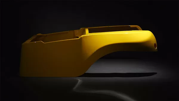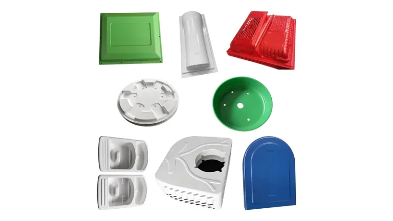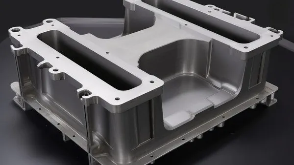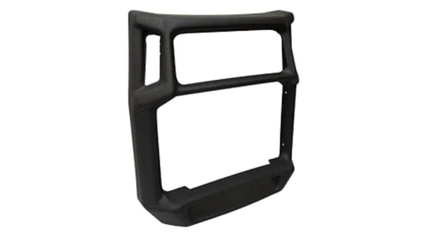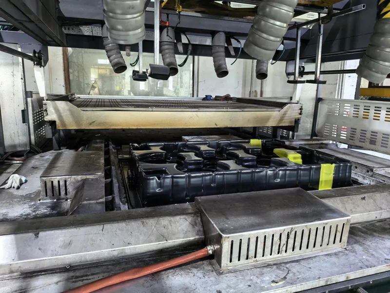
Surface finish is one of the last decisions a buyer writes into a drawing and one of the first things anyone notices on the part. On a vacuum formed housing, tray, or cover, the finish controls how the surface reads from a meter away — matte or glossy, grained or smooth, natural or coated — and how well it survives handling, cleaning, and sunlight. This article explains how finish selection works in heavy-gauge thermoforming: the three sources of finish, how materials constrain the choice, where defects appear, and how to write acceptance criteria that hold in production.
- A thermoformed finish comes from three places: the mold surface, the sheet material itself, and secondary operations such as painting or coating.
- Material comes first: PC, PMMA, and ABS hold gloss and accept coatings; HDPE, PP, and ASA carry in-mold texture reliably but resist coatings.
- Deep draws stretch the sheet unevenly, so texture depth, draft angle, and draw ratio must be reviewed together before tooling starts.
- Gloss variation across stretched zones is the most common finish defect on large formed parts; it is corrected in the process window, not at inspection.
- Finish acceptance should be written as numeric gloss readings and approved master samples, not adjectives such as “high quality.”
What Does a Finish Actually Change on a Thermoformed Part?
A finish changes how the part reflects light, how it resists wear and chemicals, and how much of the forming process it exposes to the eye. On a heavy-gauge part, the finish is mostly decided by the mold surface and the sheet material, with painting or coating reserved for what the process cannot reach.
Three finish routes exist in vacuum forming. The first is the mold surface: a textured tool reproduces its grain directly onto the hot sheet, while a polished or chrome-plated tool produces a gloss surface. The second is the material: ABS naturally reads satin, PMMA gives high clarity, and ASA keeps a matte texture stable outdoors. The third is secondary work — painting, hard coating, or edge polishing — applied after forming and trimming.
The route you pick decides the cost structure. In-mold texture adds nothing per part once the tool is paid for; secondary coatings add a per-part operation, masking and handling, and a new failure mode — adhesion — that must be inspected for the life of the part. That is why finish selection belongs in the tooling review, not in a late decoration meeting.
How Do You Match the Finish to the Material?
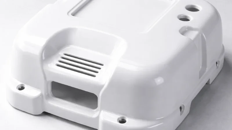
Start from the sheet, not from a color chip. PC, PMMA, and ABS hold polished-mold gloss and accept coatings well; HDPE, PP, and ASA resist coatings but carry in-mold texture reliably; and a clear cover in PC or PMMA must keep both gloss and light transmission after forming.
Coating compatibility is the column that most often forces a redesign: a paint system on polyolefin sheet needs surface treatment and still fails adhesion testing more often than the same paint on ABS. The table below is the starting matrix used in tooling reviews when a finish requirement arrives together with a material requirement.
| Sheet material | Natural surface behavior | Coating compatibility | Typical finish route |
|---|---|---|---|
| ABS / PC/ABS | Uniform satin to gloss | Good | Mold texture or paint |
| PC | High gloss, transparent | Fair | Polished mold, hard coat |
| PMMA | High clarity, glossy | Good | Polished mold, edge polish |
| ASA | Matte, UV-stable | Poor | In-mold texture only |
| HDPE / PP | Waxy, low gloss | Poor | In-mold texture only |
| TPE / TPV | Soft touch, low gloss | Poor | As-formed, uncoated |
Two material facts drive the rest. First, heat history matters: a finish must survive the part’s service temperature, and on a sheet whose deflection temperature sits close to the forming window, some coatings become the weak link. Second, flame-rated enclosures add a constraint — UL 941 classifies the flammability of plastic materials, and an equipment housing that must keep its flame rating should reach that rating through the sheet itself rather than through a finish layer that can be scratched off in service.
The plant processes sheet from 0.5 to 15 mm across a material library that runs from PVC, ABS, and HDPE to PC, PMMA, ASA, and PP/GF. For finish planning, this means material and finish can be decided together in the same tool review, instead of forcing a finish onto a sheet that cannot hold it.
Should the Finish Come From the Mold or From a Secondary Operation?
Choose the mold route whenever the texture or gloss level can be built into the tool, because it scales: after tooling, every part carries the finish with no added operation. Reserve secondary finishing for what the mold cannot produce — specific colors, anti-scratch or conductive coatings, or cosmetic repairs.
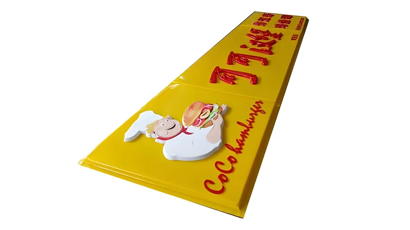
In-mold texture reproduces on every cycle and follows the part geometry exactly, including inside corners. Painting adds cost per part, creates masking and overspray work around trimmed features, and makes adhesion a permanent inspection item. A practical hybrid exists for large enclosures: form a textured or gloss surface from the tool, then paint only designated zones such as brand panels or logos.
"Painting is the cheapest way to get a high-end finish on a vacuum formed part."False
Paint looks cheap per piece until masking, handling, and rework are counted. Across a production run of formed housings, an in-mold texture or polished tool usually delivers a lower cost per part, and it cannot peel or scratch the way a coating layer can.
"Tool finish should be locked before the forming tool is cut."True
Changing a texture after tooling means re-texturing or re-placing mold surfaces and re-qualifying gloss, draft, and dimensions. Deciding grain depth, gloss target, and trim interaction at the tool review is what keeps per-part cost flat over the life of the tool.
Textured Finishes: Process Windows and Failure Modes
Texture on a formed part is a geometry decision as much as a cosmetic one. Grain depth on thermoforming tools commonly sits between roughly 0.05 and 0.3 mm, and the working rule in tooling is that texture depth needs compensating draft — a frequently used convention is about 1° of extra draft per 0.1 mm of grain depth — or the texture scrubs on vertical walls during ejection. The exact figures depend on material and mold design, which is why the texture drawing and the part drawing should be reviewed together.
Draw ratio2 is the second variable: a deep, tight part stretches the sheet more than a shallow tray, and stretched zones thin down and reproduce grain differently from compressed zones. The visible result is gloss variation — the same grain reads darker and shinier where the sheet stretched, and flatter where it did not. On parts formed from thicker sheet, the effect is stronger because the sheet carries more thermal mass into the forming window.
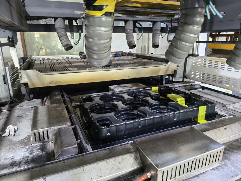
The failure modes to check on texture trials are webbing between close features, grain washout on high-draw corners, and shiny spots where the sheet touched the mold before vacuum pulled it fully. Each of these is corrected in the process — sheet temperature profile, vacuum rate, plug assist geometry — not by re-texturing the tool. For operating detail, see how a textured finish is created on a vacuum formed part and how to determine the right texture for a specific part.
"A heavier grain will hide surface defects on a deep-drawn part."False
Texture does not remove defects; it relocates them. On high-draw areas the grain stretches and gloss shifts, and any flaw on the tool becomes a repeated feature on every cycle. Deep parts need texture chosen against draw ratio and draft, not heavier texture to mask problems.
"Texture depth and part depth must be reviewed together before tooling."True
The deeper the draw, the more the sheet thins and the more grain geometry distorts. Matching grain depth to draw ratio and adding compensating draft is what keeps a texture uniform from flange to floor on a formed housing or tray.
High-Gloss and Clear Finishes
High gloss is the demanding end of finish work. The tool must be polished to a mirror — typically a machined aluminum tool with a finely polished surface or a nickel shell — and the sheet must meet it at the right temperature so imperfections do not print through. Pressure forming, which adds air pressure on top of vacuum, is the usual way in heavy-gauge thermoforming to push texture definition and gloss beyond what vacuum forming alone produces.
The plant forms parts up to about 2,500 mm in forming length, and gloss variation grows with part size because a large sheet never stretches evenly. On large enclosures and covers, the realistic gloss target is a specified range across measured points, not a single number at one corner.
For clear parts the target is twofold: surface gloss and retained light transmission. ISO 134683 specifies the method for measuring the total luminous transmittance of transparent plastics, and it is the property a clear formed cover must be verified against after forming, since forming can haze a sheet that was perfectly clear on delivery. PMMA is the reference material here — acrylic display covers are formed with high clarity and custom curved geometry — while PC is chosen when a clear guard or equipment cover also needs impact strength.
How Do You Inspect and Accept a Finish?
Write finish acceptance as numbers and samples: a gloss target in gloss units4 at defined points, an approved master sample for texture, and a defined light booth for visual checks. Adjectives such as “smooth” or “premium” cannot be inspected and will cause disputes at first article.
A workable acceptance set for a formed enclosure looks like this: gloss readings at three to five fixed points with a 60° gloss meter; the approved texture master as the grain reference; color measured against a standard where the part is painted or matched to a housing family; and cross-hatch adhesion testing for any coated zone. Trimmed edges deserve their own check — formed parts are trimmed on a 5-axis CNC centre whose outline follows the forming tool, but a cut edge still exposes raw material that may need deburring or polishing to match the visible surfaces.
"If the first article looks right, the finish will hold through production."False
A first article is one sheet, one heat cycle, and one machine setup. Sheet lot changes and heater drift move surface gloss on formed parts over a long run, which is why finish checks belong on the release plan with fixed measurement points, not only at first article approval.
"Finish checks belong on the production release plan, not just at first article."True
Gloss and texture reproduction drift with sheet lots and heater condition. Sampling fixed points on each release against the approved master and a numeric gloss target catches that drift before it reaches the customer.
FAQ
Can an existing mold be re-textured or re-polished later?
Yes, within limits. Aluminum thermoforming tools can be re-textured or re-polished, and nickel shells can be re-plated, but any change re-opens first article qualification: gloss, draft, and part geometry all move with the tool surface. Plan re-texturing as a tooling project, not a quick tweak.
Does thicker sheet give a better finish?
Not by itself. In vacuum forming, finish quality follows the mold surface, sheet temperature, and draw ratio; thickness mainly buys rigidity and heat retention. Very thick sheet can even show temperature gradients more clearly, which reads as gloss variation across large panels.
Why does gloss vary across a large formed panel?
Because the sheet does not stretch evenly. High-draw zones thin down and their surface distorts differently, which shifts how light reflects. The fix is process-side — sheet temperature profile, vacuum rate, forming speed — plus a gloss specification written as a range across fixed measurement points.
Do trimmed edges need a separate finish?
Usually yes. A trimmed edge is cut material, so it lacks the mold surface the visible faces carry. On clear acrylic parts, edges are polished to restore clarity; on opaque enclosures, deburring is normally enough. Decide the edge treatment at the tooling stage, since the trimmed outline follows the forming tool.
Where can I read more about finish options?
Start with the detailed guide to choosing the right finish for a vacuum formed part, which expands on gloss targets, texture masters, and coating trade-offs.
To keep exploring how heavy-gauge thermoforming works, explore the ZetarVac vacuum forming guide, which walks through the process from sheet selection to finished, trimmed parts. To see how finish and tooling decisions are handled in production, review how a China vacuum forming manufacturer structures tooling and finish reviews for heavy-gauge parts, or learn how the full service scope covers forming, trimming, and finishing together.
-
UL 94: the standard that classifies the flammability of plastic materials; many formed equipment enclosures must retain their rating through the finished part. ↩
-
Draw ratio: the ratio between the formed part’s surface area or depth and the original flat sheet area; higher draw ratios mean more stretching, more thinning, and more finish distortion. ↩
-
ISO 13468: the standard that specifies the method for measuring the total luminous transmittance of transparent plastics; used to verify clear formed covers after forming. ↩
-
Gloss unit (GU): the reading from a gloss meter, most commonly at a 60° geometry; used to set numeric gloss targets on formed surfaces. ↩