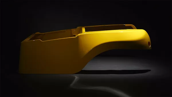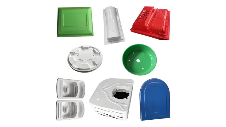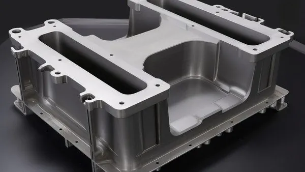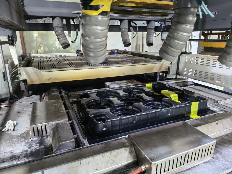
Texture on a vacuum formed part gets decided three times: when the tool surface is machined, when the sheet is selected, and when the first article is inspected. When those moments are not aligned, the grain that looked right on a flat sample can wash out on a deep draw, glare under showroom lighting, or trap dirt on a wiped-down surface. This guide walks through how engineers choose, specify, and approve texture for heavy-gauge thermoforming — the parameters that drive the decision, the failure modes to check, and the paperwork that keeps a production surface repeatable. A baseline thermoforming overview is useful context before the texture-specific detail.
- Texture is a tooling decision: it is molded into the surface and cannot be changed without re-texturing and re-proving the tool.
- Evaluate texture on a formed part, not on a flat plaque, because forming thins and stretches the surface unevenly.
- Texture depth, draft angle, and draw depth interact; deeper grains need more draft to release and to avoid burnished patches.
- Match texture class to function: glare control, scratch masking, grip, and cleanability each pull the choice in a different direction.
- Specify texture with a master plate reference, a defined gloss range, and a signed first-article sample.
- Clear PC and PMMA covers trade optical clarity for texture, so define the transmittance target before the grain is chosen.
What Does “Texture” Mean on a Vacuum Formed Part?
Texture is the engineered surface pattern of a formed part, defined by its peak-to-valley depth1 and its gloss level2, and it is produced by the tool surface rather than by a secondary operation. In heavy-gauge thermoforming, hot sheet is drawn against a textured mold under vacuum, so the pattern machined into the tool is the pattern the part carries for its entire production life.
There are three practical routes to a textured surface. Mold-in texture is engraved or etched directly into the forming tool and repeats indefinitely at no added material cost. A textured film or laminate can be formed with the sheet, which suits decorative panels but adds a material system to qualify. A post-form texture coat offers the widest visual choice but adds a finishing step, a cost per part, and a second specification to control. For most equipment housings and structural covers, mold-in texture is the default because it survives handling without chipping.
Two numbers describe any grain usefully. Peak-to-valley depth — how far the pattern rises above its valleys — typically runs from about 0.05 mm on fine grains to more than 0.5 mm on coarse industrial grains, depending on the plate standard and the toolmaker. Gloss, read with a 60° gloss meter, is the other half of the callout: the same grain at 15 GU and at 45 GU reads as two different surfaces. A texture callout without both numbers is not a specification; it is a mood.
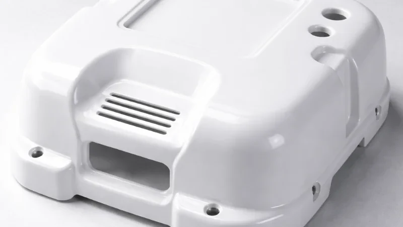
Because the pattern is carried by the tool, texture belongs in the conversation at tool design, alongside draw depth and parting lines — the same window in which you would review the basics of vacuum forming for heavy-gauge parts. Changing a grain after tool build means re-texturing and re-proving the tool, so the cheap moment to decide is before the first aluminum is cut.
ZetarVac runs more than 20 vacuum forming machines across 45+ production lines and processes sheet from 0.5 to 15 mm with a maximum forming length of about 2,500 mm — so a texture can be proven at production sheet gauge and production part size, not on a scaled-down coupon.
How Does Draw Depth Change the Texture You See?
Forming stretches the sheet over the tool, and where the sheet stretches most, the texture flattens and thins with it. The result is one grain reading two ways on the same part: crisp on thick flanges, muted on deep walls.
Thinning follows draw depth. In a moderate draw, the sidewalls of a formed housing may lose 15–25% of nominal sheet thickness; in deep draws with tight radii, local thinning above 40% is a recognized risk that depends on tool geometry, sheet temperature, and plug assist choice. Those ranges are engineering expectations rather than measured guarantees for any given part, but the direction is reliable: the more a wall stretches, the more the grain peaks smear in the draw direction. Steep walls can also take on a directional sheen, because the sheet slides against the tool while it forms.
Texture depth and draft angle3 have to be negotiated together. A deeper grain grips the tool harder on ejection and needs more draft to release cleanly — a common starting point is roughly 1° of additional draft over the smooth-surface baseline for pronounced grains, tuned per material. Too little draft shows up as burnished patches on the texture peaks and, in the worst cases, as scuffing during ejection.
"Choose texture by appearance now; forming will not change it much."False
Forming thins and stretches the sheet unevenly, so a grain validated on a flat plaque can flatten on deep walls and concentrate on thick flanges. The consequence is a part whose surface reads inconsistent under raking light — discovered only after the tool is built.
"Texture must be approved on a formed part from production-representative tooling."True
Only a formed pull shows how thinning, draft, and tool contact distort the pattern on your actual geometry. Approving the texture at first article, on parts formed at production sheet gauge, closes the gap between what the plate shows and what the part delivers.
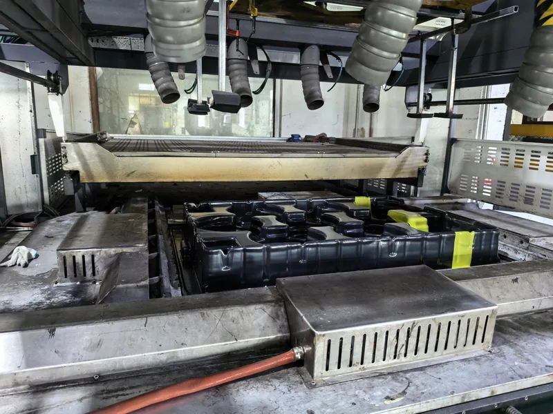
If your geometry includes a deep section, treat draw depth as the primary input and read it alongside a dedicated review of how to determine draw depth for vacuum forming. A texture that works at a 1:1 draw ratio can be the wrong choice at 2:1.
Which Texture Depth Fits Which Application?
Start from the surface’s job, not from a catalog image. Glare control, scratch masking, grip, and cleanability each pull the depth choice in a different direction, and most parts weight two of them heavily.
| Application | Primary texture job | Practical depth class | Watch-out |
|---|---|---|---|
| Equipment housings | Glare control and scratch masking | Medium grain, matte gloss | Deep grains hold cleaning residue on horizontal faces |
| Medical and diagnostic enclosures | Cleanability with low reflectance | Fine-to-medium grain | Verify the grain tolerates repeated disinfectant wiping |
| Material handling trays | Grip and part orientation | Coarse grain in functional zones | Coarse texture on sliding faces accelerates wear |
| Retail display covers | Uniform appearance over curves | Fine grain or gloss-controlled smooth | Grain flattening on steep draws |
| Outdoor equipment covers | Dirt hiding with a stable look | Medium grain on UV-stable sheet | Check gloss drift after outdoor exposure |
Treat the table as a starting filter, then narrow with the part’s real duty cycle: how often it is touched, wiped, stacked, or photographed. When a coating, printed graphic, or paint layer sits on top of the grain, coordinate both choices with the same framework used to choose a finish for a vacuum formed part, because gloss and texture interact and a mismatch is visible immediately under showroom lighting.
"Deeper texture is safer because it hides scratches and marks better."False
Deep grains amplify every thin spot and draw mark because the pattern magnifies surface variation under raking light, and they trap dirt and cleaning fluid on horizontal faces. On parts that must be wiped down, a coarse grain can fail hygiene review even though it passed the showroom test.
"Texture depth should scale with the part's cleaning and handling reality."True
Match grain depth to how the surface is touched, wiped, and inspected: fine-to-medium grains for cleaned and inspected surfaces, coarser grains reserved for grip zones and hidden functional areas. That keeps the cosmetic benefit where it helps and removes the hygiene and wear liabilities where they hurt.
How Do Material and Texture Interact?
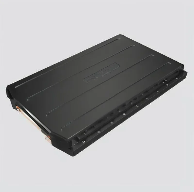
The same grain transfers differently on every resin. Amorphous thermoforming sheet such as ABS, PC, and PMMA picks up tool texture sharply, while additives, sheet gauge, and forming temperature decide how crisp that transfer stays across the part.
ABS is the workhorse for housings and trays because it etches cleanly and mattes easily, which makes fine and medium grains dependable. PC is stiffer and glossier, so surface defects read more strongly and texture does real cosmetic work hiding them. For PMMA the decision is different in kind: roughening a clear cover trades away light transmission. ISO 13468 specifies the test method for total luminous transmittance of transparent plastics — exactly the property a textured PMMA or PC cover spends when its outer face is roughened for glare control — so define the transmittance target before the grain is chosen, not after.4
Texture transfer also depends on the sheet reaching full consolidation temperature across the whole forming area; a cold sheet fills coarse grain poorly and leaves shallow, shiny patches. That is why texture reviews sit naturally next to setting the right forming temperature for vacuum forming. PC/ABS and ASA carry the same grain logic into automotive interiors and outdoor housings, while soft TPE liners use coarse texture purely for grip.
ZetarVac’s formed-part cases span an ABS seedling tray for agriculture, a PC medical equipment housing, and a PMMA retail display cover — three different texture briefs (grip, wipe-down cleanability, glare-controlled clarity) served from one material library that also covers PC/ABS, ASA, PP, and TPE.
How Do You Specify and Approve a Texture?
Specify texture with three artifacts: a master plate reference, a gloss range, and a signed first-article sample5. Anything less leaves the surface open to interpretation at exactly the moment interpretation is expensive.
Grain catalogs are not interchangeable between toolmakers, and etching depth varies with tool material and process. Pin the callout to a physical master plate held by one named party, state the acceptable gloss window at defined measurement points, and require the sample to come from the production tool rather than a trial block.
"Naming a commercial grain code guarantees an identical surface from any supplier."False
Grain catalogs are not interchangeable between toolmakers, and etched depth varies with tool material and process control. Two shops quoting the same grain name can deliver visibly different parts, and the disagreement surfaces at first article, after tool spend is already committed.
"A texture callout needs the plate reference, a gloss range, and a signed sample."True
Pin the callout to a physical master plate held by one party, state the gloss window at defined points, and sign off on a formed first article. With those three artifacts in place, texture becomes a measurable acceptance criterion instead of a taste dispute.
At first article, inspect the texture under raking light at the walls, radii, and flanges where thinning concentrates, measure gloss at fixed locations on every cavity of a multi-cavity tool, and photograph the approved part. Those records become the reference for re-texturing during tool maintenance.
Formed parts are trimmed on a 5-axis CNC centre whose outline follows the forming tool, and the plant supports prototyping, small batch, and large batch production against a reference monthly capacity of about 100,000–200,000 pieces — so a texture can be proven on finished, trimmed parts before it is committed to recurring volume.
A texture chosen late costs twice: once to re-texture the tool and again to re-prove the surface on new first articles. Choosing it at tool design costs one conversation.
FAQ
Can texture be added after forming instead of in the tool?
Yes — texture coats, paint, and applied films all work after forming, but each adds a process step, a cost per part, and a second surface specification to control. Mold-in texture stays the default for heavy gauge parts because it cannot chip off during handling.
Does texture change the strength of a thermoformed part?
Not the way a sharp notch does, but it matters indirectly. Texture sits on surfaces that thin during forming, and cosmetic repair is harder on a grain because sanding destroys the pattern. Size the wall for loads as if the surface were smooth, then treat texture as a surface decision.
How much draft does a textured surface need?
More than a smooth surface. A common starting point is about 1° of additional draft over the smooth-surface baseline for pronounced grains, tuned to the material and the grain depth, because deep peaks resist ejection and burnish without release angle.
Can clear PC or PMMA covers be textured?
Yes, but clarity is spent deliberately. Roughening the outer face reduces transmittance and adds haze, so set a transmittance or haze target first and texture only the zones that actually need glare control.
What belongs in a texture approval package?
Three artifacts: the master plate reference with its holder identified, a gloss range measured at defined points, and a signed first-article sample formed at production sheet gauge. Raking-light photographs of the approved part settle later disputes cheaply.
To keep working through surface and tooling decisions at this level of detail, walk through the ZetarVac heavy-gauge vacuum forming capability guide, which covers how formed parts move from sheet selection and forming through trimming and first-article approval — a useful next read before comparing suppliers on texture capability.
-
Peak-to-valley depth: The height difference between the highest peaks and lowest valleys of a surface texture pattern, the primary measure of grain depth. ↩
-
Gloss unit (GU): The measurement unit reported by a gloss meter, typically read at a 60° geometry, used to specify surface gloss numerically. ↩
-
Draft angle: The taper applied to vertical walls so a formed part releases from the tool without scuffing. ↩
-
ISO 13468: The standard test method for total luminous transmittance of transparent plastics, used to quantify how much light a clear formed part passes. ↩
-
First article: The initial production part inspected and signed off to verify that tooling and process parameters deliver the specified part. ↩