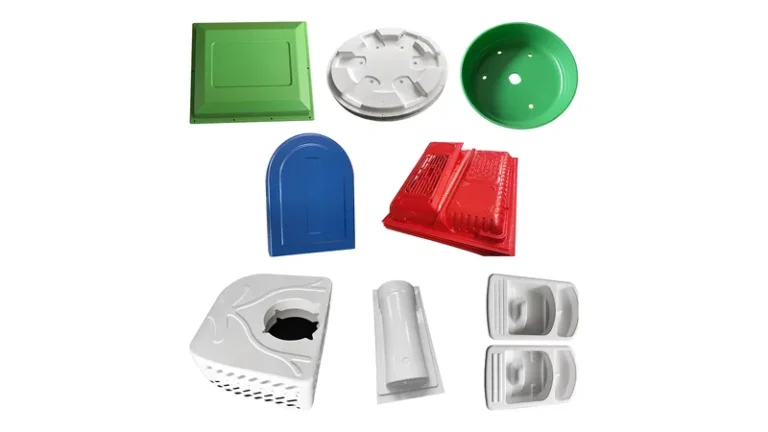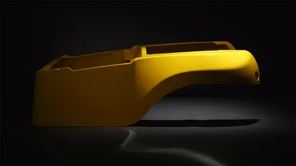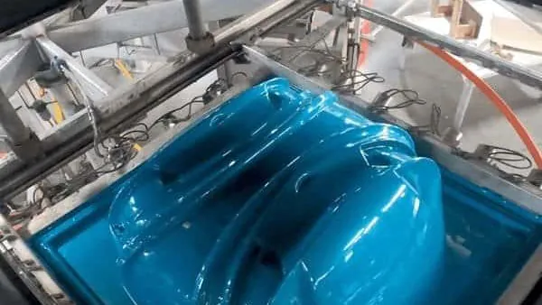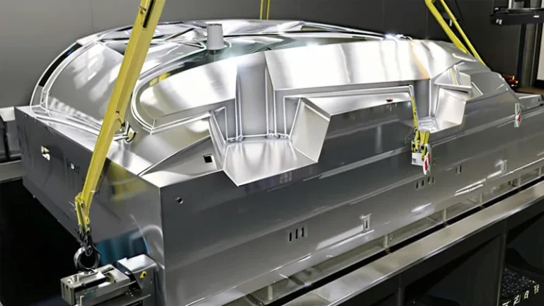
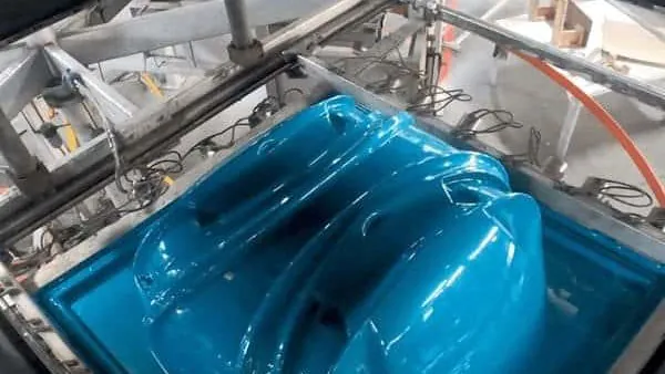
Sourcing a thermoforming mold in China is less about finding the lowest quote and more about judging whether a supplier can turn your 3D model into tooling that holds geometry over tens of thousands of forming cycles. Heavy-gauge vacuum forming places different demands on a mold than thin-gauge packaging work: deeper draws, thicker sheet, longer cycle times, and trim fixtures that define the final part outline.
This guide walks through what a complete mold package should include, how to choose between cast and machined aluminum, where prototype tooling fits, which tolerances are realistic on formed parts, and what to verify in a supplier’s build process before any metal is cut.
- A complete mold quote covers forming tool geometry, draft and shrinkage allowances, vacuum hole layout, and the trim fixture — not just the forming block.
- Cast aluminum suits large, simple panels; machined aluminum delivers the best contour and texture control on deep draws.
- A prototype mold validates geometry and material behavior cheaply before production tooling is committed.
- Vacuum forming holds the tightest control on mold-contact and trimmed surfaces, so assign tolerances by surface type.
- Sheet gauges from 0.5 to 15 mm and forming lengths up to about 2,500 mm define the part envelope to plan around.
- Standards such as UL 94 and ISO 75-2 give you objective pass criteria for formed housings and covers.
What Does a Thermoforming Mold in China Actually Include?
A complete thermoforming mold package covers more than the forming block itself. It includes male or female tool geometry with draft and shrinkage compensation, the vacuum hole and venting layout, any plug or helper features the draw requires, and the trim fixture that defines the final outline. When comparing supplier quotes, ask exactly which of these items are priced in, because mold-only pricing that excludes trim tooling simply moves that cost downstream.
The first structural decision is male versus female forming. A male tool forms the best surface on the inside of the part and distributes wall thickness differently than a female cavity, which is why the choice affects both appearance and structural consistency. Our guide to positive and negative molds compares the two in detail. Cavity count is the second decision: a single-cavity tool suits large parts such as equipment housings, while multi-cavity tools pay off on trays and smaller structural parts, as covered in our article on thermoforming mold cavities.
Draft angle is the detail most often under-specified. Formed parts release from the tool as it cools, and a working rule for heavy-gauge tooling is 1–3 degrees on visible walls, with more on deep draws or textured surfaces, adjusted to the polymer’s shrinkage behavior1. Texture adds effective draft because it increases friction between the hot sheet and the mold surface, so a deep grain can require two additional degrees that the CAD model must already contain.
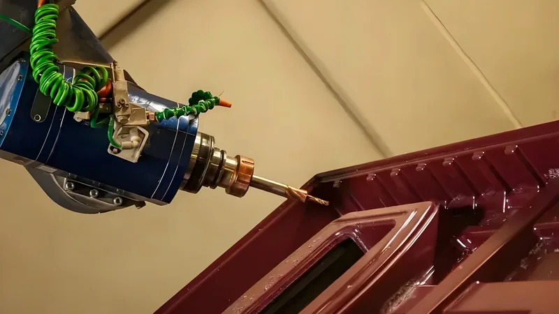
Below the forming surface, the mold is an air and thermal management device. Vacuum hole diameter and density control how quickly air is evacuated from deep pockets: too few holes leaves webs or blisters around tight radii, while oversized holes mark the visible surface. Cooling channels follow the same logic, because uniform mold temperature shortens cycle time and keeps shrinkage predictable.
Cast or Machined Aluminum: Choosing the Right Mold Construction
Mold construction is the biggest cost and lead-time lever, and the right answer depends on part size, draw depth, texture, and annual volume. Three constructions dominate heavy-gauge tooling: cast aluminum, CNC-machined aluminum, and composite or plaster tools used for prototyping. Each trades surface quality against speed and cost.
| Attribute | Cast aluminum | Machined aluminum | Composite or plaster |
|---|---|---|---|
| Surface detail | Good; porosity risk if casting quality is poor | Excellent; crisp radii and texture | Moderate; enough for geometry checks |
| Dimensional control | Good with sound castings | Best; CNC-controlled contours | Reference only |
| Lead time | Moderate; casting plus finishing | Longer; full machining | Fastest |
| Tooling cost | Lower for large, simple tools | Higher per surface area | Lowest |
| Best fit | Large panels, simple geometry | Deep draws, tight radii, textured parts | Early design validation |
For large, simple panels, casting is usually the economical route, since a sound casting finished by hand reaches cosmetic quality quickly. For deep draws, tight radii, or textured enclosures, machining from billet wins because every contour is CNC-controlled and there is no porosity to chase during finishing. Prototype tools exist to answer geometry questions and should be treated as disposable.
Our plant runs more than 20 vacuum forming machines processing sheet from 0.5 to 15 mm with forming lengths up to about 2,500 mm, within 45+ production lines in total. Quote your mold against a stated machine window like this rather than a catalog maximum, because platen size and forming length decide whether a large panel forms in one shot or needs a redesign.
Whatever construction you choose, make the quoted mold envelope match the forming machine rather than the reverse. A tool sized for a 2,500 mm forming length is wasted on equipment that cannot heat that sheet uniformly, and a supplier who confirms the envelope early has answered half of your feasibility questions.
"A mold quoted in China always costs more once freight, duties, and rework are added."False
Landed cost only exceeds a local quote when the two quotes cover different scopes. A mold package that includes trim fixtures and trial parts routinely closes the apparent price gap, so compare identical scope first and add freight and duties to both sides.
"Total molded-part cost over the tool's life is the right basis for comparison."True
A mold is a capital item amortized across every part it forms. Cycle time, scrap rate, and maintenance intervals usually outweigh the invoice difference between two toolmakers, and all three are measurable during trial runs.
How Does a Prototype Mold De-Risk a Production Program?
A prototype mold validates part geometry, draw depth, sheet thickness, and material behavior for a fraction of production tooling cost. In heavy-gauge programs it is the cheapest point to discover a draw that will not fill or a radius that will not release.
Prototype tools are typically cast aluminum, epoxy composites, or plaster, and each exists to answer a specific question cheaply. Plaster and composite tools reveal whether a draw fills, where the sheet thins, and how radii release, which is enough to revise a model before committing to metal. Our article on plaster thermoforming molds covers where these tools fit and where they stop being useful.
The value shows up clearly on complex parts. One PC housing formed for medical and diagnostic equipment carried a large curved surface with custom cut-outs, mounting holes, and internal reinforcement; proving the draw and the trim strategy on prototype tooling prevented an expensive revision of the production mold. The same logic protected a high-clarity PMMA display cover for retail use, where surface quality on the tool had to be proven before the production texture was applied.
"First-article approval proves the mold will hold tolerances across the whole production run."False
A first article is one part formed at one set of sheet temperatures and cycle times. Without a documented process window and wall thickness measured across several trial cycles, drift in heating, sag, and cooling only shows up once volume production starts.
"Production stability requires a documented process window, not a single good part."True
Stable forming means the part stays in tolerance when sheet batch, ambient conditions, and cycle time vary within defined limits. Ask for the trial report that establishes those limits before you approve the tool.
Treat prototype results as a data set, not a formality. Record the sheet temperature settings, cycle time, and measured wall thickness from each trial, then hand that record to whoever cuts the production tool.
Which Tolerances Can Vacuum Forming Hold Consistently?
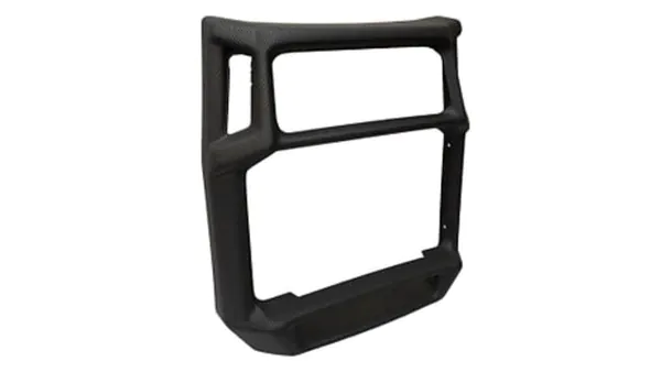
Vacuum forming controls the mold-contact side of a part far better than the free-form side. Tight, repeatable tolerances are realistic on trimmed outlines, flanges, and hole positions, while free-formed walls vary with sheet gauge, heating uniformity, and sag.
The practical method is to split the part into tolerance zones. Mold-contact surfaces, trimmed flanges, and holes cut by the trim fixture hold the tightest control. Free-formed side walls need looser bands, and the datum strategy decides much of the rest: because trimmed outlines follow the forming tool on 5-axis trimming, the datum you choose in CAD determines which surfaces end up tight and which absorb variation. When a formed panel mates with a metal frame, the mismatch in thermal expansion between polymer and steel2 can matter more than the mold tolerance itself at temperature extremes.
Material selection sets the limits behind those zones, and the standards give you objective wording for drawings. Heat deflection temperature tells you how close an enclosure can sit to a heat source before it deforms: ISO 75-2 specifies the method for determining the deflection temperature of plastics under a defined flexural load3, which is why housing drawings usually state an HDT requirement for the sheet grade. Where ignition resistance matters, UL 94 classifies the flammability of plastic materials from HB up to 5VA4, and many equipment covers specify a V-0 grade.
If a formed cover contributes to a sealed enclosure, its protection level is defined by IEC 605295, and the trim fixture must hold the sealing flange flat enough to support that rating.
Our material library spans ABS, PC, PMMA, HDPE, LDPE, PP, PA6/PA66, POM, TPE, TPU, TPV, PC/ABS, ASA, and PP/GF for formed parts. A supplier who forms all of these in-house compensates the tool for the actual polymer’s shrinkage instead of a handbook average, which matters most on parts with mating flanges or fixed hole positions.
A quick way to pressure-test a supplier on tolerances is to ask which surfaces they would measure first, and how. Shops that answer with surface-specific zones and named measurement methods are working from real process control. Shops that answer with one blanket number are quoting a hope.
"The same 3D model is enough for any shop to build a correct forming mold."False
A CAD file contains geometry, but not decisions: draft direction, shrinkage compensation for the chosen polymer, venting layout, and trimming datums all change the tool. Two shops given the same file can build molds that produce different parts.
"A mold-ready release specifies material, draft, shrinkage, venting intent, and trim datums."True
These decisions are cheap on paper and expensive in aluminum. Releasing them with the model makes supplier quotes comparable and removes the most common source of first-tool disputes.
How Do You Judge a Supplier’s Mold-Build Process Before Cutting Metal?
Judge the process, not the price. A credible mold builder shows you the CAD review notes, the machining strategy, the venting and cooling design, and a trial plan on a machine with the same platen size your production will run on.
Ask for the review deliverables before awarding the job: a marked-up CAD review with draft, shrinkage, and parting line notes; the venting map; the cooling concept; and the proposed trimming datum. A supplier who returns these documents within days is demonstrating the engineering capacity that actually holds tolerances. One neutral reference worth reading while you compare proposals is the SPE Thermoforming Division, whose published material describes how forming shops qualify tools, sheet, and processes.
Then insist on a mold trial on equipment comparable to your production press, with formed parts measured against the drawing rather than eyeballed. A useful trial report lists wall thickness at defined points, trim accuracy on the fixture, and every deviation with a corrective action. Without that report, first articles are opinions with paperwork.
Formed parts in our plant are trimmed on a 5-axis CNC trimming centre, so the trimmed outline follows the forming tool directly. When you compare quotes, ask whether trim fixtures are included and how the trimming datum is defined — that single line item separates a complete mold package from a forming block that still needs a second supplier.
FAQ
How much does a heavy-gauge thermoforming mold cost in China?
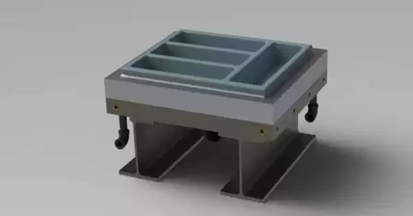
Price is driven by forming area, draw depth, cavity count, texture, and construction — not by geography alone. A large single-cavity cast tool and a compact machined multi-cavity tool can land in similar ranges for opposite reasons. The useful comparison is scope: quote the same mold package, including trim fixtures and trial parts, across two or three suppliers and compare the engineering responses, not just the totals.
How long does mold fabrication take?
Typical industry ranges are: composite or plaster prototype tools in days to roughly two weeks; cast aluminum production tools in several weeks including casting, finishing, and texture; and fully machined tools longer as size and detail grow. Real schedules depend on part complexity, texture sourcing, and the supplier’s current load, so treat any fixed promise with caution.
Can one mold run different sheet materials?
Only within limits. A tool is compensated for one polymer’s shrinkage, and moving an enclosure from ABS to PP shifts the flange, the hole positions, and the surface finish. PC and PC/ABS grades are close enough to share tooling in many cases, but changing polymer families usually means reviewing draft and trim geometry again.
What files should I prepare for an accurate mold quote?
Prepare a 3D model in a neutral format such as STEP, a 2D drawing with tolerance zones assigned by surface, the target sheet thickness and material grade, the trim outline, and expected annual volume. Add service environment notes — temperature, UV exposure, flammability requirements — because these decide material and mold texture before pricing starts.
Who owns the mold once it is paid for?
Ownership is a contract term, not a default. Purchase agreements commonly state whether the tool is buyer property, where it is stored between runs, whether it can be moved on request, and who pays for maintenance. Settle these points at quotation stage, because they are far harder to negotiate after the first production run.
To keep building your own judgment before you shortlist suppliers, explore our vacuum forming capability overview, or see how tooling, forming, and trimming fit together as a China vacuum forming manufacturer. Both walk through the process in the depth this guide could only summarize.
-
Draft angle: The tapered wall built into a forming mold so a cooled part releases cleanly, expressed in degrees of taper relative to the pull direction. ↩
-
Coefficient of thermal expansion (CTE): The fractional change in a material’s dimensions per degree of temperature change, relevant when formed polymer parts mate with metal frames. ↩
-
Heat deflection temperature (HDT): The temperature at which a plastic test bar deflects a defined amount under a specified flexural load, measured per ISO 75-2. ↩
-
UL 94: A flammability classification standard for plastic materials, rating ignition resistance and burn behavior from HB up to 5VA. ↩
-
IP code: The ingress protection rating defined in IEC 60529, classifying how well an enclosure seals against dust and water. ↩