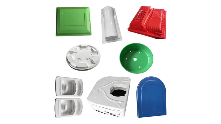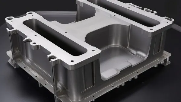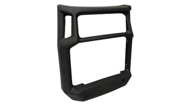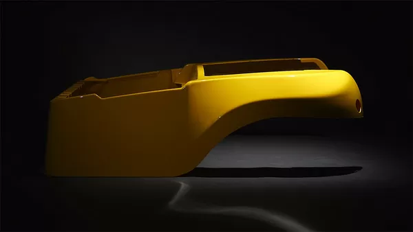
When a project needs large, rigid plastic parts — machine enclosures, equipment covers, industrial trays, structural panels — heavy-gauge thermoforming is usually the first process family to evaluate. The concept is simple: heat a plastic sheet, draw it over a mold with vacuum, and trim the result. The engineering inside each step, however, decides whether the part holds dimension in production. This guide walks through the complete vacuum forming process step by step — sheet selection, heating, forming, cooling, and trimming — and at each stage explains the parameters that matter, the defects that appear when those parameters drift, and the checks that keep a heavy-gauge process under control.
- Heavy-gauge thermoforming runs in five stages: sheet selection and preparation, clamping, heating, forming, and trimming to final dimensions.
- Heating is the most defect-sensitive step; zone-to-zone sheet temperature uniformity matters more than raw heater power.
- Vacuum forming shapes the sheet with atmospheric pressure; pressure forming adds compressed air when cosmetic sharpness is required.
- Heavy-gauge sheet typically spans 0.5–15 mm, with formed parts up to about 2,500 mm in length.
- A passed first article does not guarantee production stability; sheet lots and heater drift still need periodic revalidation.
- Validation combines standardized tests — tensile, heat deflection, flammability — with wall-thickness mapping on the finished part.
What Are the Main Steps of the Thermoforming Process?
The thermoforming process has five steps: selecting and preparing the plastic sheet, clamping it in a frame, heating it to the forming window, drawing it over a mold with vacuum, then cooling and trimming the formed part to final dimensions. In heavy-gauge work, each step is a discrete engineering stage with its own parameters and inspection points.
In heavy-gauge production the sheet arrives as cut-to-size blanks rather than roll stock, so the cycle is discrete: load a blank, heat, form, cool, unload, and only then trim. The untrimmed part keeps its clamped flange until after forming, because that flange seals the vacuum and later becomes the trimming reference.
Each step also hands a specific risk to the next one. A sheet heated unevenly becomes a part with thin corners; a shell demolded too hot warps before it reaches the trim fixture; a trimming datum chosen carelessly throws mounting holes off the mating surface. The sections below follow the sequence and flag those hand-offs. For a more detailed narrative, see the step-by-step heavy-gauge thermoforming guide on this site.
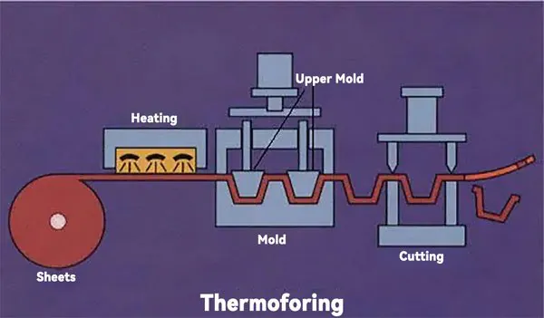
Step 1: Sheet Selection and Preparation
Every thermoforming outcome is decided first at the sheet, because gauge and resin define both the forming window and the properties of the finished part. Heavy-gauge work commonly runs from about 1.5 mm upward, with structural housings and trays typically in the 2–10 mm band. The starting gauge must also survive the part’s draw ratio1 — deep geometries stretch the sheet until thin corners fall below the functional minimum if the blank was chosen too conservatively.
Moisture is the next gate. ABS, PC, and PC/ABS absorb ambient humidity and must be dried before heating; otherwise trapped water flashes to steam and appears as blisters or voids in the formed wall. Olefin sheets such as HDPE and PP are less hygroscopic but shrink more, so warpage control shifts from drying to cooling.
The table below summarizes the resins most often specified for heavy-gauge parts and the forming consideration for each.
| Material | Typical heavy-gauge applications | Forming consideration |
|---|---|---|
| ABS | Equipment housings, cases, guards, automotive interiors | Dry before forming; wide, forgiving window |
| PC | Clear guards, equipment protection covers | High forming temperature; drying is critical |
| PC/ABS | Automotive interiors, equipment housings | Balanced impact and heat resistance |
| HDPE | Industrial trays, equipment liners, storage boxes | Higher shrinkage; control cooling to limit warpage |
| PP | Trays, packaging, automotive interior parts | Watch sag and warpage during cooling |
| PMMA | Clear covers, luminaires, display parts | Heat gently to protect optical clarity |
| ASA | Outdoor equipment housings, automotive exterior parts | UV-stable surface; window similar to ABS |
For the two most common housing resins, the trade-offs are compared in detail in PC vs ABS in thermoforming.
ZetarVac processes sheet from 0.5 to 15 mm with a qualified material library spanning ABS, PC, HDPE, LDPE, PP, PMMA, PA6/PA66, POM, TPE, TPU, TPV, PC/ABS, ASA, and PP/GF. For a buyer, that breadth matters most at the edges of the design space: ASA for outdoor housings, PC/ABS for automotive interiors, and PMMA for high-clarity covers each form differently, so the sheet should be selected with the forming window in mind, not after the tool is cut.
Step 2: Heating — Where Most Defects Are Born
Heating turns a rigid blank into a formable membrane, and it is where most heavy-gauge defects originate. Radiant panels are divided into independently controlled zones, and sheet above roughly 3 mm is normally heated from both sides, because a single-sided heater leaves the core cold while the outer skin overheats. Amorphous resins such as ABS, PC, and PMMA offer a broad rubbery range and forgive small errors; crystalline resins such as HDPE and PP pass through their narrow forming window quickly, which makes zone balance and heater timing far less forgiving.
Sheet temperature — not heater temperature — is the real process variable. Operators read the surface with infrared pyrometers and watch the sag that develops as the sheet softens. Typical engineering ranges sit near 130–180 °C at the sheet surface for ABS and roughly 170–200 °C for PC, with olefins generally forming in the 140–170 °C band; these values depend on grade, gauge, and machine, so treat them as trial starting points. The Vicat softening temperature2 marks where the material begins to soften under load, and visible sag develops shortly above it.
Uneven heating surfaces downstream as webbing between tall features, thin corners, optical distortion in clear parts, or bubbles in under-dried sheet. Zone balance is therefore checked before committing a production gauge, using a flat mapping blank with thermocouples or a thermal camera pass across the sheet area.
"Once the sheet reaches the target surface temperature, it is ready to form."False
Surface pyrometers only read the outer skin, while heavy-gauge sheet is often several millimetres thick and the core lags well behind. Forming on a surface reading alone produces wall-thickness imbalance and trapped bubbles, and the defects only surface after forming and trimming.
"Sag depth is a process signal, not a defect in itself."True
A smooth, even sag across the whole blank indicates the sheet has entered its forming window uniformly. Operators use a consistent sag trigger to start the forming step, while uneven or runaway sag points to heater zone imbalance and predicts webbing or thin corners.
Step 3: Forming — How Does Vacuum Forming Shape the Sheet?
Vacuum forming shapes the sheet by clamping the heated blank over a mold and evacuating the air between sheet and tool, so atmospheric pressure presses the plastic against the mold surface. Mold style, vacuum-hole layout, and any pre-stretch mechanism together decide how wall thickness ends up distributed across the part.
Male and female tooling distribute thickness in opposite ways. A male mold stretches the sheet over a raised form, leaving a thick base and progressively thinner side walls; a female cavity lets material pool at the bottom while the rim thins out. Deep draws combine both problems, which is why a plug assist pushes the sheet partway before vacuum is applied and billow pre-stretch inflates the sheet slightly to even out the gauge before the tool closes.
Vacuum itself is engineered, not simply switched on. Holes are concentrated where crisp detail is needed and opened into vent channels elsewhere; too few ports leave radii soft, while too many leave pin marks on cosmetic faces. Where sharp texture or crisp edges are required on a visible surface, pressure forming adds compressed air above the sheet on top of vacuum, multiplying the forming force at the cost of a more complex, sealed tool.
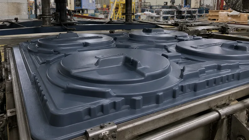
Tooling for heavy-gauge work is typically machined aluminum, and its surface finish transfers directly to the part, which is why mold machining quality shows up on every cycle.
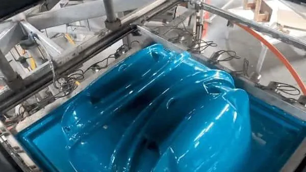
ZetarVac runs more than 20 vacuum forming and thermoforming machines, with a maximum forming length of about 2,500 mm across a 0.5–15 mm sheet range. That envelope covers everything from a benchtop instrument cover to a full-length machine enclosure formed in one piece — often the difference between a sealed housing and one assembled from several panels.
Step 4: Cooling, Demolding, and Trimming
The formed shell must cool below its heat deflection temperature3 before demolding, or it distorts under its own residual stress the moment it leaves the tool. ISO 75-2 defines the heat-deflection test that measures the temperature at which a plastic specimen deflects under a specified flexural load, and it is the practical reference for judging when a formed shell is rigid enough to release. Thick sections and crystalline resins cool slowly, so heavy-gauge machines use forced air and, for very thick HDPE or PP parts, water mist to cut cycle time without shocking the surface.
Cooling also fixes warpage. Parts with large flat panels are often held in simple fixtures until they approach ambient temperature, because a shell released hot keeps shrinking asymmetrically as it cools.
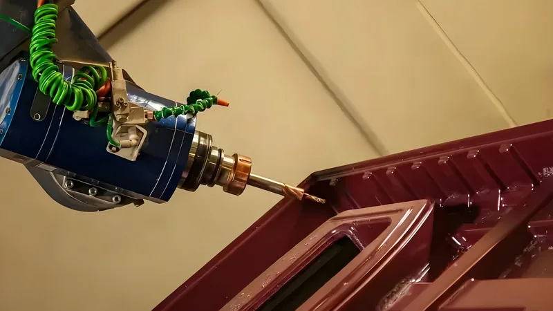
Trimming turns the formed shell into a finished part. The untrimmed body still carries its clamping flange, and in heavy-gauge work that flange is removed by machining rather than by hand: a 5-axis CNC trimming centre follows the geometry defined by the forming tool, so cut edges land exactly where the design expects them even on deep, compound-curved housings. Cut-outs, mounting holes, and stiffening features are machined in the same setup, which keeps hole-to-surface relationships tight.
Across 45+ production lines, ZetarVac holds a reference monthly capacity of about 100,000–200,000 pieces and supports prototyping, small batches, and large series on the same process base. For a buyer, that means the sheet and trim parameters proven on prototypes do not need to be reinvented when volumes grow.
How Do You Validate a Thermoformed Part?
Validation combines standardized material tests on formed sheet with dimensional and functional checks on the trimmed part. Tensile, heat-deflection, and flammability data confirm the material survived forming, while wall-thickness maps and fit checks confirm the geometry.
Material validation starts with the sheet after forming, not just as received. ISO 527-2 defines the standardized tensile test for plastics: a dumbbell specimen is pulled at a controlled rate to measure strength, modulus, and elongation, and running it on formed material4 confirms the heating cycle did not degrade the resin below design allowables.
Housings for electrical equipment add flammability requirements — UL 94 classifies plastic materials by their burning behavior5, and many formed enclosures must meet a specified rating before the finished equipment can pass its own approvals. Clear formed parts such as PMMA display covers are checked against ISO 13468, which specifies the measurement of total luminous transmittance, while tray and guard applications may add ISO 6603-2, the instrumented puncture-impact test for rigid plastics.
Dimensional validation centres on wall-thickness distribution, the most revealing single measurement in thermoforming. A thickness map — by ultrasonic probe or sawn sections — exposes heater imbalance, draw-ratio limits, and plug-assist settings in one dataset, and tracking minimum thickness against specification catches drift long before functional failures. Critical trimmed dimensions are measured on a CMM or fixture gauge, and mounting-hole positions are checked against the mating frame. Industry references such as the SPE Thermoforming Division publish process guidance aligned with these checks and are worth consulting when writing a test plan.
"First-article approval means the process is stable for volume production."False
A first article verifies tooling geometry and setup on a single sheet lot. Resin lot changes, heater drift, and ambient shifts can move wall distribution and shrinkage between approval and volume runs, so periodic revalidation and in-process thickness checks remain necessary.
"Wall-thickness distribution is the best single indicator of process health."True
A thickness map exposes heater uniformity, draw-ratio limits, and plug-assist settings in one measurement. Tracking minimum thickness against specification catches process drift before parts fail functional tests downstream.
FAQ
How long does a heavy-gauge thermoforming cycle take?
Cycle time is dominated by heating and cooling, and both scale with sheet thickness. Blanks in the 1–3 mm range may form in one to two minutes, while thick structural sections of 8–15 mm take substantially longer. The exact figures depend on resin, gauge, and machine, so trials on representative sheet are the only reliable source.
What is the difference between vacuum forming and pressure forming?
Vacuum forming relies on atmospheric pressure alone — about one bar — to press the sheet against the mold. Pressure forming adds compressed air above the sheet, roughly multiplying the forming force, which produces sharper detail and texture on cosmetic surfaces at the cost of a sealed, more expensive tool.
What sheet thickness counts as heavy gauge?
Definitions vary between shops, but heavy gauge generally means cut-sheet forming from roughly 1.5 mm upward, while thin-gauge work is roll-fed and stays below that. In practice ZetarVac processes sheet from 0.5 to 15 mm, so the working envelope covers most parts a roll-fed line cannot form.
Can formed parts hold tight tolerances?
As-formed dimensions carry the resin’s shrinkage and are therefore looser than machined features. Critical outline dimensions, holes, and cut-outs reach machining-grade accuracy because they are trimmed on a 5-axis CNC after forming. Tolerance strategy should assign tight callouts to machined features wherever the design allows.
Which materials are best for equipment housings?
ABS and PC/ABS are the default choices for indoor housings and guards. ASA is specified when the part lives outdoors, and PC when impact strength or transparency drives the design. All of these form well in heavy gauge, so the choice usually comes down to environment and regulatory requirements rather than formability.
Where can I read more about the process?
To keep digging into this process, explore ZetarVac’s vacuum forming capabilities to see how the steps above are applied to housings, trays, and structural parts, or see how a China-based heavy-gauge forming partner organizes tooling, materials, and volume production for the same process.
-
Draw ratio: The ratio of the formed part’s depth or area to the original sheet area, indicating how far the sheet must stretch during forming. ↩
-
Vicat softening temperature: The temperature at which a flat-headed needle penetrates a plastic specimen to a defined depth, indicating where a formed part begins to soften and sag. ↩
-
HDT: Heat deflection temperature, the temperature at which a plastic specimen deflects a defined amount under a specified flexural load. ↩
-
ISO 527-2: The standardized tensile test for plastics, used to verify strength and elongation of thermoformed sheet and formed parts. ↩
-
UL 94: A flammability standard that classifies plastic materials by burning behavior, commonly required for formed electrical equipment enclosures. ↩