When a pipe comes off an extrusion line out of round, wavy, or thin on one side, the cause is rarely a single bad setting. Diameter, wall thickness, and surface quality are the joint output of melt condition, die head geometry, sizing, cooling, and haul-off speed, all acting at the same time. This guide covers the pipe defects that appear most often in pipe and profile extrusion, the physical mechanism behind each one, and the measurements that confirm a root cause instead of guessing at one. For a broader overview of the process itself, start with our guide to plastic extrusion molding.
- Most pipe defects trace back to three zones: the die head, the sizing sleeve, and the haul-off.
- Ovality is a geometric defect; it is corrected at the die head and sizing sleeve, not at the haul-off.
- Sharkskin and melt fracture are melt-flow instabilities, addressed through melt temperature and die land before any resin change.
- Circumferential wall-thickness drift usually indicates die land eccentricity or uneven cooling around the sizing sleeve.
- First-article approval does not guarantee stability; verify dimensions over a multi-hour production run.
- Standards such as ASTM D2241 and ISO 4427 define the dimensions a pipe inspection plan must verify.
What Counts as a Pipe Defect in Extrusion?
Any deviation from the specified geometry, surface, or material performance of a pipe counts as a defect: out-of-tolerance outside diameter, ovality, wall thickness outside the band, surface marks such as die lines or sharkskin, internal voids, gels, discoloration, and loss of pressure rating. Each defect maps to a specific process zone, which is what makes structured troubleshooting possible.
A practical way to organize them is by family. Dimensional defects include outside-diameter error, ovality, and wall-thickness drift. Surface defects include die lines, sharkskin, melt fracture1, gels, and contamination specks. Structural defects include voids, weak weld lines behind spider legs, and poor interlayer bonding in multi-layer co-extrusion. Performance defects — reduced pressure rating, low impact strength, excessive heat reversion — often have no visible symptom at all, which is why material verification matters as much as visual inspection.
Dimensional requirements are not arbitrary. ASTM D2241 covers rigid PVC plastic pipe in SDR-PR series and fixes the outside-diameter and wall-thickness relationships that a dimensional inspection plan has to verify2. For polyethylene pressure pipe, ISO 4427 specifies the material and dimensional requirements for water-supply systems, so minimum wall on those products is a compliance matter rather than a preference.
Which Pipe Defects Originate at the Die Head?
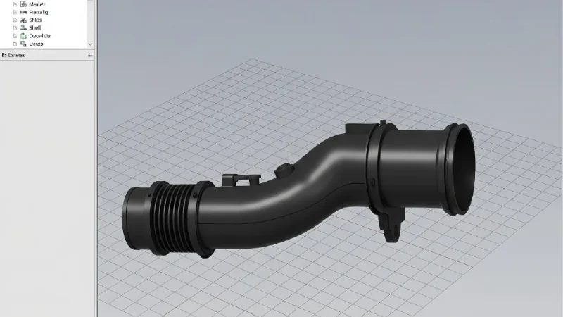
Die lines, sharkskin, melt fracture, gels, and asymmetric wall distribution all originate at or immediately downstream of the die head. A defect that repeats at a fixed angular position, or at constant spacing along the pipe, usually points here first rather than to cooling or haul-off.
The die head shapes the melt into an annulus, and everything it gets wrong is built into the product. Weld lines are the classic structural example: in a spider-type tube head, melt streams reunite around the spider legs, and if the melt arrives cold or the pressure is low, the weld line remains as a permanent weak plane that a burst test will find quickly. Raising die body temperature and improving flow-channel streamlining are the standard corrections.
Surface defects have their own signatures. Die lines run continuously along the pipe and usually indicate a scratched, scored, or degraded die land3. Sharkskin appears as small, regular transverse ridges caused by stick-slip of the melt at the die exit. Gross melt fracture shows up as irregular distortion once wall shear stress passes a material-dependent threshold.
"Sharkskin means the resin is defective, so the only fix is to switch material."False
Most sharkskin is a surface-flow instability at the die exit, driven by melt temperature, die land condition, and line speed. Switching resin is the most expensive lever available and usually unnecessary; melt-zone and die corrections remove it at a fraction of the cost.
"Sharkskin should be addressed at the melt temperature and the die land first."True
Raising melt temperature within the material window, polishing or adjusting the die land, and trimming line speed attack the stick-slip mechanism directly. A resin or additive change is justified only after these levers are exhausted and documented.
Wall distribution starts at the annular gap. If the die land is not concentric, no downstream adjustment produces a pipe with even wall; the operator must correct the die bolts at the head and verify with circumferential wall cuts at several positions. For multi-layer products, the same logic applies to every layer, which makes the die design the decisive variable — see our article on co-extrusion die heads and multi-layer profiles.
Why Does Pipe Come Off the Line Oval or With Drifting Wall Thickness?
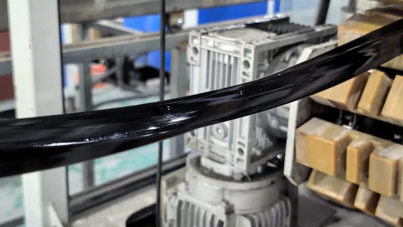
Ovality comes from uneven cooling, gravity sag of hot melt, or a misaligned or worn sizing sleeve, while circumferential wall drift usually indicates die land eccentricity. Both are geometric problems, and neither is reliably fixed by changing haul-off speed.
Sizing is where geometry is locked in. In vacuum sizing, a calibrated sleeve sets the outside diameter while vacuum holes pull the hot pipe against it; uneven vacuum distribution or unequal cooling-water temperatures freeze the pipe out of round. On large-diameter PE lines, gravity sag before the wall freezes adds measurable ovality, which is why multi-stage sizing with staggered vacuum sections is common practice.
Drawdown adds a second variable. The ratio between the die opening and the finished pipe4 is set by haul-off speed versus melt output, and excessive drawdown thins the wall non-uniformly while amplifying any eccentricity already present in the die. As general engineering practice, sleeves sized closer to the final diameter — lower drawdown — give more stable geometry at the cost of longer sizing sections.
"An out-of-round pipe can be pulled back into tolerance by adjusting haul-off speed."False
Haul-off speed changes overall drawdown and cut length, not the cross-sectional shape of the pipe. Chasing ovality at the haul-off usually worsens wall distribution while the shape error itself remains untouched.
"Ovality is corrected at the die head and sizing sleeve, then verified with a laser gauge."True
Die bolt adjustment and sleeve alignment set the cross-section, and a non-contact gauge placed after cooling confirms the correction. Measuring a hot pipe with a handheld caliper tells you more about thermal contraction than about the product.
Wall drift that appears only after startup, and worsens over hours, often points to thermal soak rather than mechanical eccentricity. Die and head temperatures keep rising toward equilibrium for the first one to two hours of a run, and a die centered cold will drift off-center hot. Documenting the warm-up behavior and re-checking concentricity after thermal stabilization is standard practice on a disciplined line.
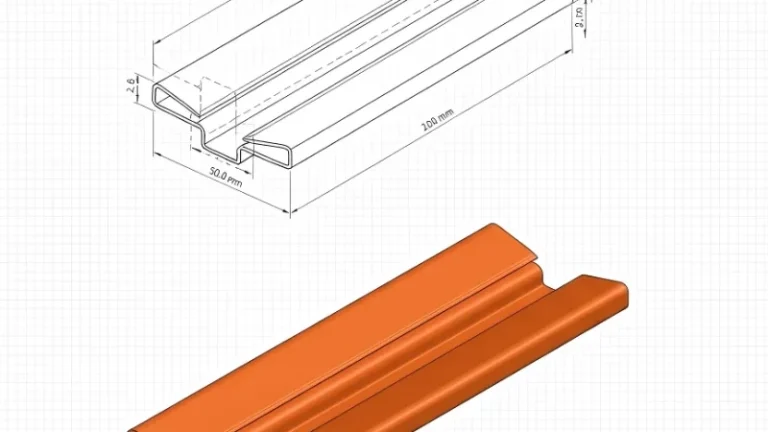
ZetarVac develops non-standard profile sections to customer drawings with a minimum achievable dimensional tolerance of ±0.05 mm on the profile cross-section, subject to material and section geometry. Tolerance at that level is only sustainable when die alignment and sizing are treated as controlled, verifiable process variables rather than one-time setup steps.
How Do You Catch Pipe Defects Before They Become Scrap?
Combine continuous in-line measurement with a fixed off-line sampling routine: laser gauges for outside diameter and ovality, ultrasonic or gravimetric wall monitoring, and scheduled wall cuts and surface checks. The objective is to detect drift trends early, not merely to reject bad pipe at the end of the line.
In-line laser micrometers measure outside diameter and ovality thousands of times per minute and can feed closed-loop control to haul-off speed or melt output. Ultrasonic wall-thickness sensors mounted in the cooling track monitor wall distribution around and along the pipe in real time, while gravimetric control — comparing extruded weight per meter against target — catches slow output drift that diameter gauges alone can miss.
Off-line checks still anchor the plan. Wall cuts at four circumferential positions verify concentricity against the die-bolt settings; surface inspection under defined lighting catches die lines, gels, and contamination that gloss hides; and periodic material checks keep the thermal side honest. ISO 306 defines the Vicat softening temperature test, a comparative indicator of a thermoplastic’s resistance to short-term heat and creep5, useful for confirming that incoming material still matches the grade the process was tuned for.
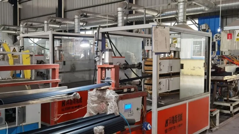
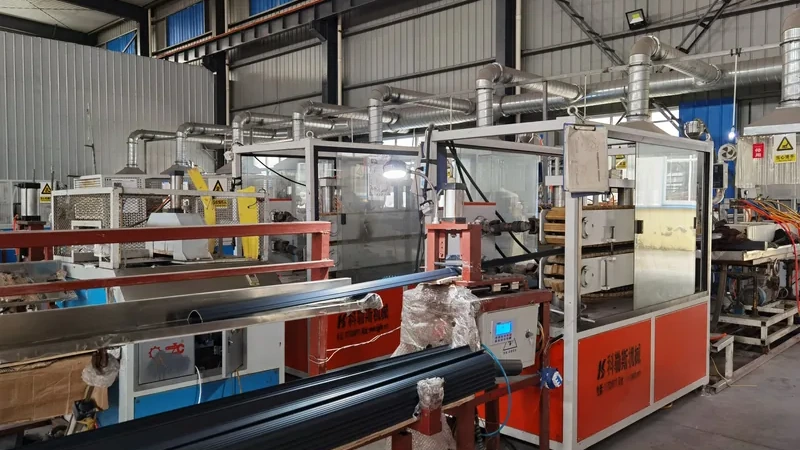
ZetarVac runs 7+ automated extrusion lines with a reference monthly capacity of about 300–500 tonnes across those lines, within a plant of 45+ production lines in total. At that throughput, a wall drift that looks trivial on one sample cut becomes measurable scrap within a single shift, which is why in-line gauging is treated as production equipment rather than an accessory.
The economics justify the instrumentation. Scrap pipe is rarely reusable in pressure-rated products, so every meter produced out of tolerance is a full material loss plus the energy already invested in it. A gauging package that catches drift an hour earlier routinely pays for itself within a single production campaign.
Which Corrections Fix the Most Common Pipe Defects Fastest?
Start with the correction that matches the defect family: geometry defects are corrected at the die head and sizing sleeve, surface defects at the melt and die land, and structural defects at melt temperature and material condition. The table below summarizes the fastest first moves.
| Defect | Most likely root cause | First correction to try | Verify with |
|---|---|---|---|
| Ovality | Sleeve misalignment, uneven cooling, gravity sag | Re-center the sizing sleeve; balance cooling water | Laser ovality gauge after cooling |
| Wall-thickness drift | Die land eccentricity | Adjust die bolts; re-check melt uniformity | Circumferential wall cuts at several positions |
| Die lines | Damaged or degraded die land | Inspect and polish the die land; purge | Surface check under defined lighting |
| Sharkskin | Melt too cold, line speed too high | Raise melt temperature within the window; trim speed | Surface comparison at matched lighting |
| Gels and specks | Long residence time, degraded purge | Purge thoroughly; shorten residence time | Continuous surface inspection |
| Weak weld line | Cold melt at the spider | Raise die body temperature | Burst or pressure test on a sample |
The table lists the first correction, not the only one. If a first correction does not move the defect, stop and re-measure rather than stacking adjustments; compounding changes makes root-cause attribution impossible. A structured walkthrough of the wider defect family is available in our extrusion defect troubleshooting guide.
For tubing used as cable insulation or jacket, surface and structural quality carry regulatory weight as well. UL 1581 is the reference standard for electrical wires, cables, and flexible cords, and it frames the tests that extruded insulation and jacket materials must withstand — a reminder that a die line on clear tubing can be more than a cosmetic issue.
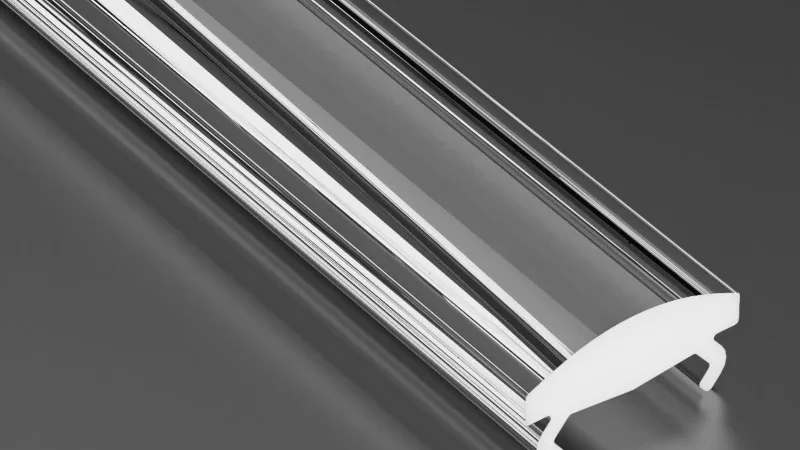
One representative ZetarVac product is a transparent PVC electronic tube profile, produced by single extrusion for electrical and electronic cable protection, insulation, and guiding. On clear tubing, gels, die lines, and contamination are visible immediately to the customer, which is why surface-quality defects are controlled with the same discipline as dimensions.
FAQ
What causes marks that repeat at regular intervals along the pipe?
Periodic marks with constant spacing usually come from mechanical sources downstream of the die: a damaged sizing sleeve, a worn calibrator, or haul-off belt impressions. Marks at a fixed angular position rather than a fixed spacing point back to the die head instead.
Can out-of-round pipe be corrected after extrusion?
Not practically. The cross-section is frozen once the wall cools below the material’s softening range, and re-heating finished pressure pipe is not an acceptable correction. Ovality has to be fixed at the die head and sizing sleeve during the run.
How tight should wall-thickness tolerance be on extruded pipe?
It follows the application standard, not preference. In SDR-rated systems, wall thickness relates directly to pressure capacity, so minimum wall is a compliance limit. A practical process target sits tighter than the specification, leaving margin for normal drift.
Does higher line speed always create more pipe defects?
No, but speed raises shear rate and shortens cooling time, so marginal settings fail first. A line that is stable at moderate speed with well-conditioned melt often produces cleaner pipe than an aggressively tuned one; widen the process window before chasing speed.
When you are evaluating suppliers for a pipe or profile program, the useful question is not only which defects a line can produce, but which ones it keeps out of a multi-tonne run. To compare your current specification against production reality, send your drawings or talk to an engineer at ZetarVac.
-
Melt fracture: a melt-flow instability in which stressed polymer leaves the die with a distorted surface, ranging from fine sharkskin to gross distortion. ↩
-
SDR: Standard Dimension Ratio, the ratio of a pipe’s outside diameter to its wall thickness, used to classify pressure-rated pipe dimensions. ↩
-
Die land: the final parallel section of an extrusion die through which melt flows just before exit; its condition and alignment strongly influence surface quality and wall distribution. ↩
-
Drawdown ratio: the ratio between the cross-section of the die opening and that of the finished product, set by the balance of haul-off speed and melt output. ↩
-
Vicat softening temperature: the temperature at which a flat needle penetrates a thermoplastic specimen to a defined depth, used as a comparative heat-resistance indicator per ISO 306. ↩