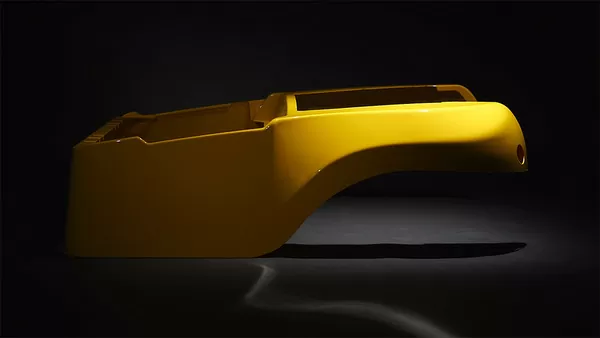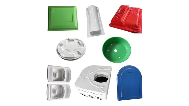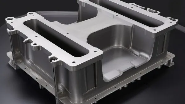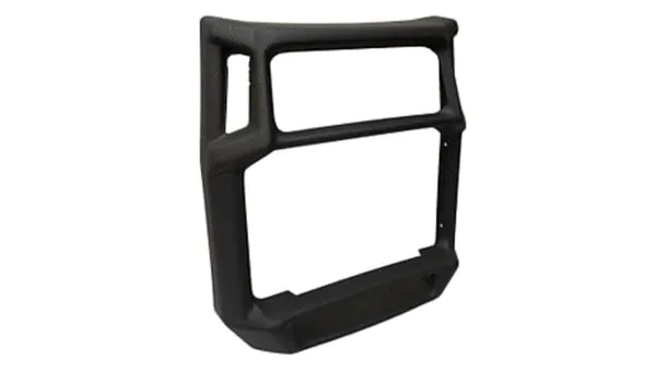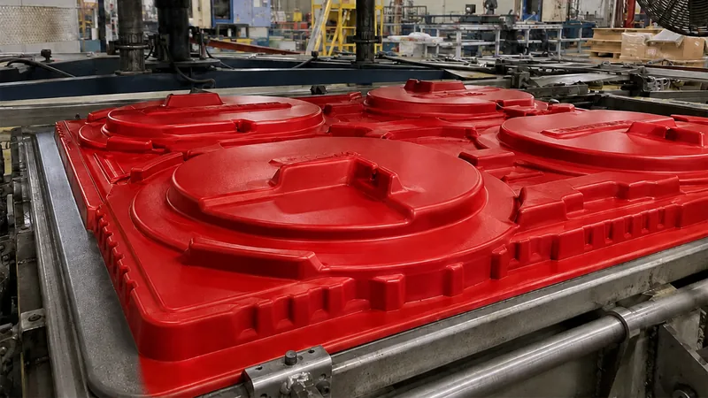
A seamless vacuum formed part reads as one continuous shell: no bonded panels, no visible joint lines, no fastener rows crossing a cosmetic surface. In heavy-gauge thermoforming, that result comes from a chain of engineering decisions — forming envelope, mold parting geometry, material behavior, draw depth and trimming strategy — rather than from any single trick. This guide walks through each decision the way a forming engineer would, including the process windows, the failure modes that introduce visible lines, and the checks that confirm the finished part will stay seam-free in production.
- A seam-free part is thermoformed from one sheet in one cycle; seams come from joining sections, mold parting lines or webbing — not from the forming process itself.
- Match the developed part size to the forming envelope: ZetarVac processes sheet from 0.5–15 mm with forming lengths up to about 2,500 mm, so most housings form as a single shell.
- Place the mold parting plane on a flange or non-cosmetic edge, and give walls 2–5° or more of draft so witness lines stay out of sight.
- Deep draws thin the sheet unevenly; pre-stretch, plug assist and a higher starting gauge keep minimum wall above spec.
- Trim on 5-axis CNC equipment so cutouts and mounting holes follow the formed tool without adding flat joint faces.
- Validate with recognized tests — tensile per ISO 527-2, heat resistance by HDT — rather than judging the surface by eye.
What Does a “Seamless” Vacuum Formed Part Actually Mean?
A seamless part is a shell thermoformed from one continuous sheet of plastic, so its visible surface carries no weld lines, bonded joints or fastener rows. The phrase describes the finished appearance; vacuum forming itself never creates seams, because it stretches and cools a single sheet against a mold.
Visible lines have four usual origins. Oversized parts that exceed the forming envelope are sectioned and joined with adhesive, fasteners or welded flanges. The mold parting plane leaves a witness line wherever the sheet drapes over a tool edge. Deep pockets and tall, closely spaced ribs bridge the sheet between features, creating folds known as webbing. Finally, secondary operations — hand trimming, re-fixturing, bonded trim strips — can add edges that read as seams even though the forming was clean.
The distinction matters when you specify the part. A structural enclosure may accept a designed joint on a hidden face; a medical equipment housing or a retail display cover usually cannot show any line across its primary surface. Define which faces are cosmetic before tooling starts, because every later decision — mold orientation, draft, trim path — hangs on that map.
How Do You Form a Part Without Seams?
Form the complete geometry in one cycle from a single sheet: check the developed surface against the machine envelope, orient the parting plane onto a non-cosmetic face, and give every wall enough draft and radii for the sheet to drape instead of bridging. Get those three right and the process takes care of the rest.
Start with the envelope check. A formed shell begins as a flat clamped sheet, so the developed area — the part surface unfolded — must fit inside the machine’s forming area. At ZetarVac, sheet thickness from 0.5 to 15 mm and a maximum forming length of about 2,500 mm cover most equipment housings, machine guards and logistics trays as single-piece forms. If the developed size exceeds the envelope, the realistic options are a redesigned one-piece geometry or a deliberate two-part assembly; a geometry that almost fits always ends in a seam somewhere.
Next, mold orientation. A female cavity forms the outer surface against the mold wall, which preserves texture and fine detail; a male core gives more uniform wall distribution on deep draws because the sheet wraps the peak first. Place the parting plane along a flange, a bottom edge or a face that sits against another component, and the witness line disappears into the assembly. Moving it after tooling is cut means rework, so this is a design-review decision, not a shop-floor adjustment.
Draft and radii decide whether the sheet drapes or folds. Female cavity walls generally need at least 1–3° of draft and male cores 3–5° or more, with deeper features demanding the upper end; inside corners tighter than roughly one sheet thickness encourage webbing1. Generous radii also spread the stretch across the corner, which keeps the wall inside the thickness budget discussed later.
Vacuum hole layout and forming pressure complete the picture. Small holes, typically 0.5–1.5 mm, belong in deep pockets and corners where air traps; flat panels vent fine through coarser holes. When the outer surface needs crisp detail, sharp radii or molded texture, pressure forming presses the heated sheet against the mold with roughly 0.4–0.7 MPa of air on top of vacuum, which sharpens definition without adding any joint.
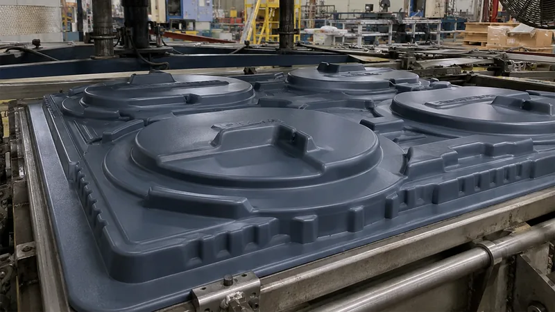
ZetarVac runs 45+ production lines across the plant, more than 20 of them vacuum forming and thermoforming machines, and supports sheet thickness from 0.5 to 15 mm with forming lengths up to about 2,500 mm. For most enclosure and tray geometries that means the entire shell forms in one cycle, with no sectioning or bonded joints required.
One caution: a single-cycle form still has a parting line wherever the tool and clamp frame meet the sheet. That line is placed, not eliminated — which is why the design review should walk the parting geometry face by face before mold steel is cut.
"Any visible line on a formed part means the forming process failed."False
In vacuum forming, the shell is stretched from one sheet, so the process itself cannot generate a weld seam. Lines come from the mold parting plane, webbing between features or post-forming joining — all geometry and planning issues. Chasing a process fix wastes time; the correction belongs in part and mold design.
"Parting-line placement is locked at the design stage, before mold steel is cut."True
Once the mold exists, the witness line follows the tool. Reviewing parting-plane position face by face during design review costs hours; relocating it afterward costs retooling. It is the cheapest quality decision in the whole project.
Which Materials and Standards Apply to Seamless Formed Parts?
Every common heavy-gauge sheet material can produce a seam-free shell; the material decides how deep you can draw, how sharp the radii stay and which standards the finished part must pass. The seamless outcome depends on matching the material to the geometry, not on any special grade.
For housings and enclosures, ABS and PC/ABS dominate because they form over a wide temperature window and distribute wall thickness predictably. PC suits clear guards and equipment protection covers but punishes sharp corners with stress whitening. HDPE and PP handle deep draws and large radii well, PMMA delivers clarity for display and luminaire covers, and ASA extends ABS-like forming behavior to outdoor housings.
| Material | Typical seamless parts | Forming behavior to watch |
|---|---|---|
| ABS | Equipment housings, cases, guards | Wide window, predictable wall distribution |
| PC/ABS | Machine enclosures, medical covers | Stiffer at temperature; balance heater zones |
| PC | Clear guards, protection covers | Stress whitening on tight radii |
| HDPE | Industrial trays, liners | Deep draws OK; shrinkage and warp need control |
| PP | Trays, automotive interior parts | Warpage control on large flat panels |
| PMMA | Display covers, luminaires | Brittle; use generous radii and slow cooling |
| ASA | Outdoor equipment housings | UV stable; forming window similar to ABS |
Sheet and part qualification should lean on recognized tests rather than appearance. ISO 527-2 defines the standard tensile test run on thermoformed sheet, and running it on the specific sheet lot tells you the material’s strength and elongation before it ever meets the mold. For enclosure work, UL 94 governs the flammability of plastic materials and is required for many equipment enclosures, while IEC 60529 defines the IP-code degrees of protection that formed covers are rated against. Where heat resistance matters — a housing near a power supply, for example — HDT2 data predicts the temperature at which a formed panel starts to deflect under load.
How Does Sheet Thickness and Draw Depth Affect Seam-Free Forming?
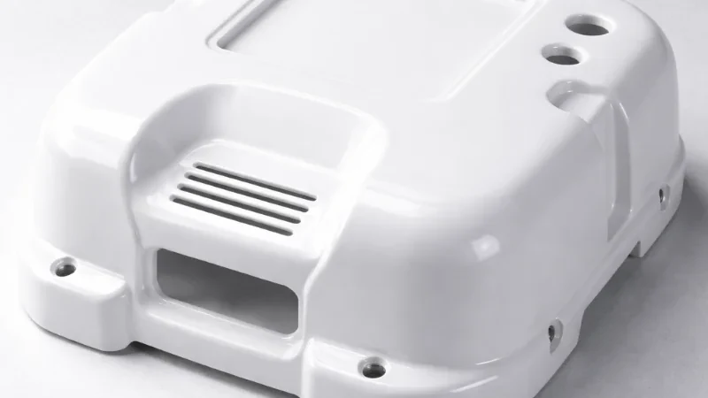
Deep draws stretch the sheet unevenly: corners and pocket floors can end up far thinner than the starting gauge, depending on the draw ratio3. A seam-free part with uniform walls therefore needs the right starting thickness, pre-stretch and plug geometry chosen for the material and depth.
The draw ratio compares the developed surface area of the formed part with the clamped sheet area; as it rises, each unit of sheet feeds more surface and thins more. A practical habit is to select the starting gauge so that predicted corner thinning still leaves the minimum functional wall, often by budgeting a 1.3–2.0 factor for moderate draws and more for deep pockets. Exact numbers depend on material and tooling, so thickness mapping on a trial form is the honest way to set the gauge.
Temperature and pre-stretch do the fine adjustment. Sheet surface temperature typically sits well above the material’s HDT during forming, and heater zones are balanced so the sheet sags evenly rather than hot-spotting. For deep pockets, billow pre-stretch bulges the sheet downward before the mold rises, and a plug assist4 pushes material into the pocket floor first — both actions move thickness from areas with surplus into the corners that need it.
Webbing is the signature failure of tall, closely spaced features: the sheet bridges between two peaks and folds into a visible crease that looks like a seam. Countermeasures are geometric spacing, larger radii between features, faster vacuum application and a hotter, more extensible sheet. If the layout cannot change, relocating one rib is usually cheaper than chasing the fold with process settings.
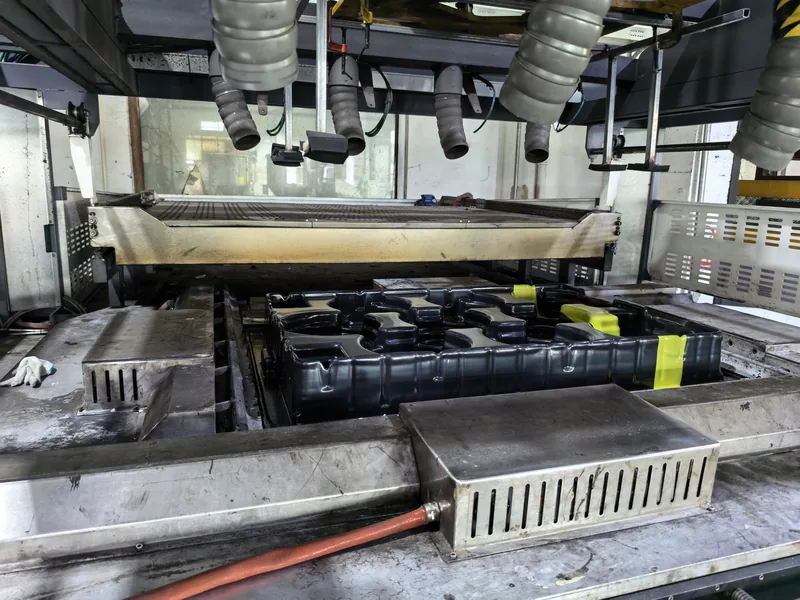
Verification closes the loop. Map wall thickness on trimmed parts at corners, pocket floors and flanges, compare against the zoned minimum-wall specification, and record heater settings with the results so the window is reproducible.
"If the first article is seamless and passes inspection, the process is stable."False
First articles are usually formed at carefully tuned settings on a fresh sheet lot. Heater output drifts, sheet lots change in melt strength, and vacuum leaks develop quietly — none of which show on a single kept sample. Stability comes from monitoring, not from one good part.
"Zoned wall-thickness checks on production parts are the practical acceptance method."True
Measuring thickness at corners, pocket floors and flanges on sampled parts catches drift before it produces scrap or a visible fold. Tie the check to a zoned minimum-wall spec and the acceptance decision becomes objective rather than visual.
How Does Trimming and Finishing Preserve the Seamless Surface?
Trimming never adds a seam, but careless fixturing and hand finishing can. Cut every cutout, hole and flange edge on 5-axis CNC equipment programmed from the same geometry as the forming tool.
A 5-axis trimming centre holds the formed part the way the mold did and machines the outline, windows and mounting features in one setup, so no re-fixturing witness appears and edges stay parallel to the formed surface. Cutouts, hinge points and mounting holes hold consistent from the first article to the last batch part.
Finishing choices affect how the surface reads as much as the forming does. Mold texture hides minor witness marks and gloss variation, while a high-gloss finish amplifies them; our guide to creating a textured finish on a vacuum formed part explains how texture is planned into the tool. Undercut features can also be formed rather than added as joined parts, which is covered in our guide to creating undercuts in a vacuum formed part, and the trade-offs between surface options are compared in our guide to choosing the right finish for a vacuum formed part.
Because the trimmed outline follows the forming tool on ZetarVac’s 5-axis CNC trimming centre, cutouts and mounting features are machined without flattening the shell or splitting it into sections. The PC medical equipment housing in ZetarVac’s project files — a large, complex curved cover with custom cut-outs, mounting holes and reinforcement — stays one continuous part through forming and trimming.
FAQ: Seamless Vacuum Forming Questions
Can you form a seamless part larger than the forming machine’s envelope?
No. A part whose developed size exceeds the envelope cannot be vacuum formed in one cycle, so some joint is unavoidable. The engineering options are a one-piece redesign or a deliberate two-part assembly with a flanged joint on a non-cosmetic face.
Does pressure forming produce a more seamless result than vacuum forming?
Not in the seam sense — both form one sheet, so neither creates weld lines. Pressure forming presses the sheet harder against the mold, which sharpens radii, texture and detail on the outer surface and can make minor witness marks less noticeable.
What draft angle keeps parting lines out of sight?
Draft does not remove the parting line; parting-plane placement does. Put the line on a flange or non-cosmetic edge, and use at least 1–3° on female cavity walls and 3–5° or more on male cores so the sheet releases cleanly.
How much wall thinning should a deep-draw part budget for?
It depends on the draw ratio and material, but corners thin much faster than flat panels. Plan the starting gauge so the thinnest predicted zone still meets the minimum functional wall, and confirm with thickness mapping on a trial form rather than a rule of thumb.
Which material is best for a seamless clear cover?
PMMA offers the highest clarity for display and luminaire covers, while PC brings impact resistance to guards and equipment protection covers. Total luminous transmittance of transparent plastics is standardized in ISO 13468, so clarity can be specified and verified rather than judged visually.
To keep building on these design decisions, explore our complete vacuum forming process overview, or see how we approach single-shell enclosures and heavy-gauge projects as a China vacuum forming manufacturer. Both guides walk through the tooling, thickness and trimming choices behind seam-free parts in more detail.
-
Webbing: Unwanted folds or creases that form when a heated sheet bridges between tall or closely spaced mold features instead of draping over them. ↩
-
HDT: Heat deflection temperature — the temperature at which a standard bar deflects a set amount under flexural load, reported per ASTM D648 or ISO 75-2. ↩
-
Draw ratio: The ratio of the formed part’s developed surface area to the original clamped sheet area; higher ratios mean more stretching and more thinning. ↩
-
Plug assist: A mechanically driven plug that pre-stretches the sheet into deep pockets before vacuum is applied, improving wall distribution. ↩