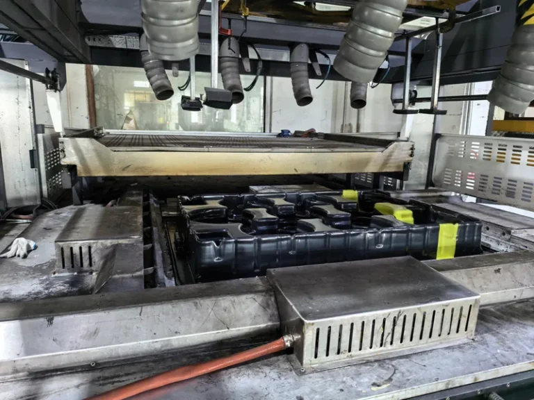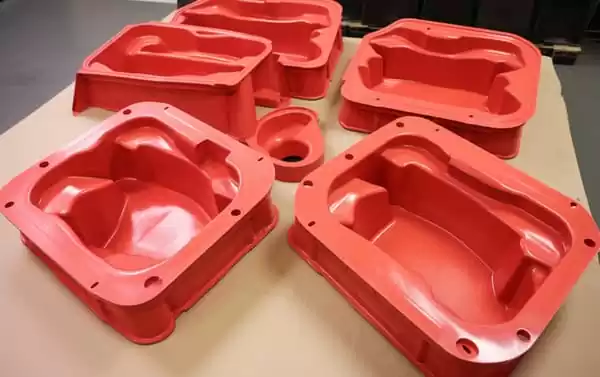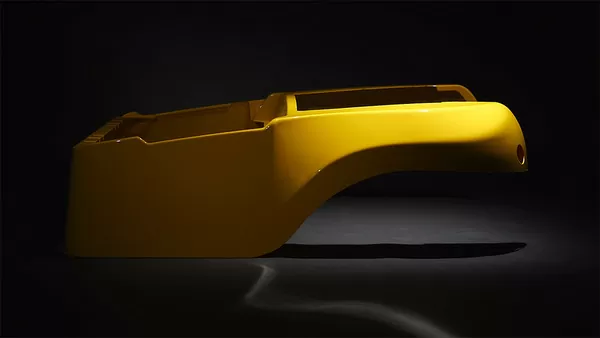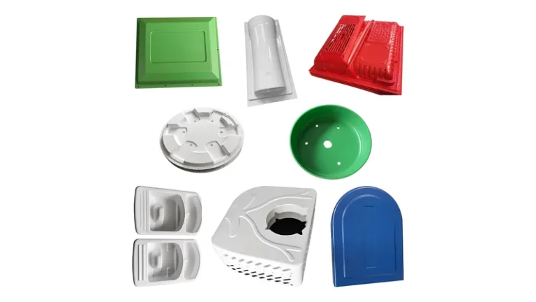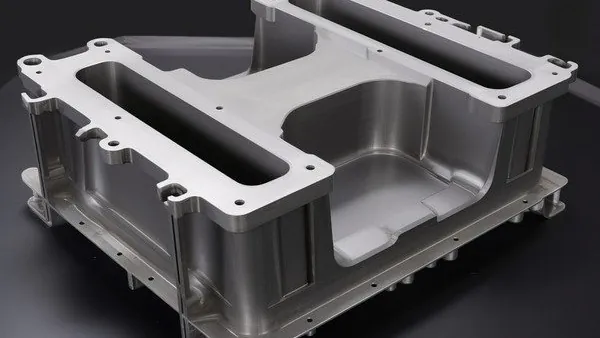
A vacuum forming mold decides more about a finished part than any other item in the process. It sets the geometry, the surface finish, the wall-thickness distribution, and most of the cost that appears later in trimming and rework. Buyers who compare tools on price alone usually meet the difference in production.
This guide walks through the mold types used in heavy-gauge thermoforming, the materials tools are built from, and the design details — draft, venting, shrinkage — that decide whether a mold runs cleanly at production speed. The frame of reference is industrial work: equipment housings, trays, liners, and formed structural parts, where volumes and tolerances are real engineering decisions.
- Vacuum forming molds fall into four working categories — male, female, matched, and plug-assist — and each moves the tool-contact surface, with its detail and finish, to a different side of the part.
- Mold material — wood, composite, cast aluminium, machined aluminium — should follow part size, batch volume, and required detail, not a fixed hierarchy.
- Draft angles, vent holes, and shrinkage scaling are settled at the mold design stage and dominate rework risk later.
- The tool-contact surface carries the most consistent wall thickness and the best surface finish; decide early which face of the part that must be.
- Mold qualification needs a sustained run at production sheet gauge and cycle time, not just a passing first article.
Which Mold Types Are Used in Vacuum Forming?
Four mold types cover nearly all vacuum forming work: male (positive) molds, female (negative) molds, matched molds that combine both halves, and plug-assist setups that add a driven plug ahead of the vacuum. Each type changes which surface of the part touches the tool, so each moves where detail, finish, and thickness consistency land. Pressure forming extends the family by adding air pressure on top of vacuum for sharper texture on cosmetic faces.
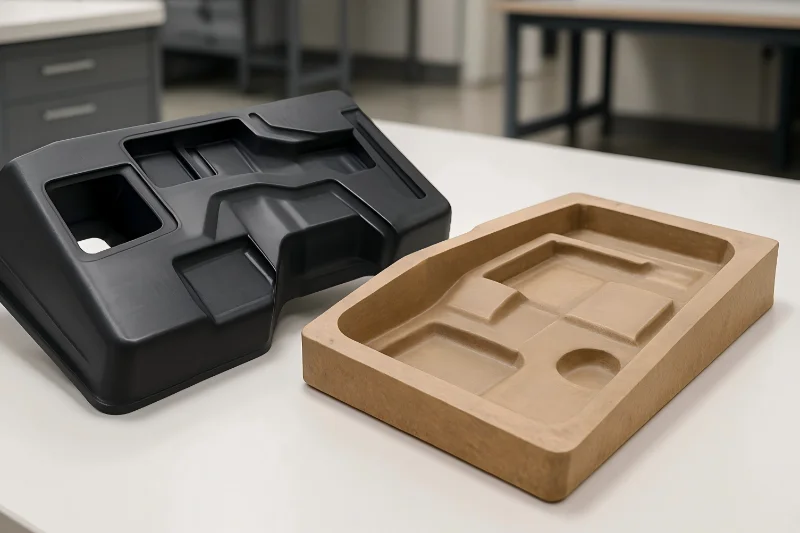
Male (positive) molds. A male mold is a raised, convex body that the heated sheet drapes over. The inside of the finished part — the face that touched the tool — gets the sharpest detail and the most uniform thickness, while the outer surface stretches and thins over tall corners. Male tools suit trays, liners, and housings whose inside surface carries mounting or locating features, and they cost less because the tool is a single body.
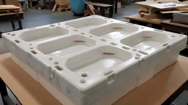
Female (negative) molds. A female mold is a recessed cavity the sheet is drawn down into. The outer face of the part now contacts the tool, so exterior texture and crisp detail stay on the cosmetic surface — the reason user-facing housings and covers are usually formed into female tools. The trade is thinning in deep draws, so depth relative to opening width needs watching, often with plug assist.
Matched molds. A matched set pairs male and female halves that close on the hot sheet between them. Both major surfaces are tool-controlled, thickness distribution is more even than either single-sided tool can reach, and ribs or logos can be formed in register on both faces. Two tool bodies, alignment, and higher forming force make it the costlier option, justified on structural panels and parts where both faces matter.
Plug-assist forming. Plug assist is an add-on to a female tool: a heated plug mechanically pre-stretches the sheet into the cavity before vacuum pulls it home, pushing material into corners that vacuum would otherwise thin first. It is standard practice on deep-draw enclosures formed from ABS, HDPE, or PC sheet. Heavy-gauge thermoforming raises the stakes on all of this, because thick sheet needs more forming force, more heat, and longer cycles than thin-gauge practice.
| Mold type | How the sheet meets the tool | Best detail and finish on | Thickness behaviour | Relative tooling cost |
|---|---|---|---|---|
| Male (positive) | Sheet drapes over a raised body | Inside surface | Outer face thins over tall features | Low to moderate |
| Female (negative) | Sheet draws into a cavity | Outside surface | Thins in deep draws and corners | Low to moderate |
| Matched | Sheet closes between both halves | Both surfaces | Most uniform distribution | High |
| Plug-assist | Plug pre-stretches before vacuum | Outside surface of female parts | Reduces corner thinning on deep draws | Moderate; adds plug tooling |
"A male mold and a female mold will produce the same part, just mirrored."False
The two tools put the tool-contact surface on opposite sides of the part, which moves the sharp detail, the texture, and the most consistent wall thickness with it. Specify the wrong side and the cosmetic face ends up with the stretched, less controlled surface.
"The tool-contact surface carries the best finish and the most uniform wall thickness."True
Wherever the hot sheet touches the mold it cools quickly against the tool, freezing in the mold’s texture and a controlled thickness. The first design question is therefore not male versus female in the abstract, but which face of the part must be the controlled one.
CustomPartNet’s thermoforming overview is a fair reference for the basic mechanics; the rest of this guide concentrates on the heavy-gauge decisions that decide industrial parts.
How Does Mold Material Affect Cost and Volume?
Mold material is a volume decision. Wood and composite tools carry low cost and fast turnaround but finite life; cast aluminium suits medium volumes and complex contours; machined aluminium delivers the best surface detail and the longest service where volumes or tolerances are high.
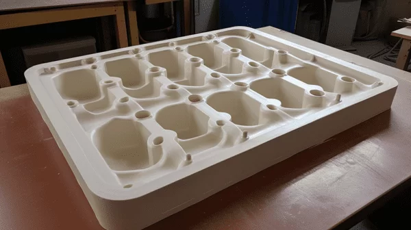
Wood tooling. Machined and hand-fitted wood is the fastest route to a forming tool and is easy to modify between prototype loops. Its limits are wear and moisture: repeated thermal cycles soften edges and radii over time, so wood earns its place on prototypes and short runs.
Composite and epoxy-faced tooling. Sealing a wood-based tool with an epoxy face buys a better forming surface and longer life at a modest cost step — a sensible middle ground for pilot batches and large parts where full aluminium tooling would dominate the budget.
Cast aluminium. Casting fills large, complex contours without machining the whole volume, and cooling passages and vent details can be built into the pattern. Surface porosity is the known trade, so cosmetic tools get sealing and polishing. Cast tools are workhorses for medium-volume trays and enclosures.
Machined aluminium. Cutting the tool from billet gives the best dimensional control and the finest surface detail, and the tool holds that condition across long runs. It is the default for production housings and precision parts — higher cost up front, lowest drift over time.
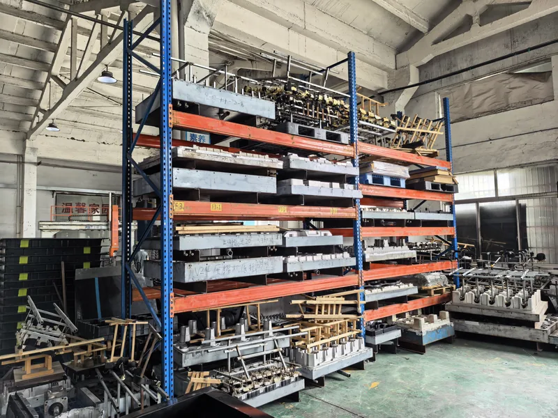
ZetarVac runs more than 20 vacuum forming machines that process sheet from 0.5 to 15 mm, with forming lengths up to about 2,500 mm, alongside 45+ production lines across the plant. Tools are sized to that envelope, and prototyping, small batch, and large batch production are all supported, so tooling material can be matched to the batch instead of forced into one rule.
Material behaviour around the tool matters too. ABS and PVC form cooler and gentler than PC or PA6, and hotter sheet is harder on softer tool faces, so the pairing is worth settling early — our overview of the materials that can be used in plastic vacuum forming covers it before mold material is fixed.
"Wood molds are only for prototypes and can never justify a production run."False
Wood and composite tools are legitimate for short and medium runs and for large parts where an aluminium tool would dominate the budget. The engineering limit is surface wear over thermal cycles, not a rule that wood cannot produce saleable parts.
"Mold material should follow part size, batch volume, and required detail."True
A large agricultural tray produced in modest quantities can run economically on wood or composite tooling, while a high-volume enclosure with textured cosmetic surfaces justifies machined aluminium. Judging every tool by one material rule overpays some projects and under-tools others.
In the end, cost per part decides: a cheap tool that needs constant refurbishment is not cheap, and a premium tool on a short program is money the part never recovers.
Draft, Venting, and Shrinkage: Details That Decide Mold Performance
Three mold design details cause more scrapped parts than the choice of male versus female ever will: draft, venting, and shrinkage scaling.
Draft gives the formed part a release path. Most vertical surfaces carry 1–3 degrees of draft as an engineering norm, with more on tall male features and on textured female walls, where texture drags if the angle is too shallow1. Without it, parts hang on the tool, hot surfaces score, and cycle time stretches while operators coax pieces free.
Venting is how vacuum actually reaches the sheet. Air trapped between sheet and tool escapes through small holes or slots, concentrated in corners, pockets, and deep detail; on male tools the vents are usually drilled blind from behind so no witness mark shows on the part. Vents too large leave tell-tale dots on cosmetic surfaces; vents too few leave trapped air, glossy patches, and unfilled detail.
Shrinkage scaling is built into the mold, not corrected afterwards. The tool is cut larger by the mould shrinkage of the specific polymer and sheet gauge, and that number differs enough between HDPE, ABS, PC, and PA6 that a tool scaled for one material will not hold tolerance for another.
Temperature closes the loop. A mold that runs cold at start-up and hot two hours in is effectively two different tools with two different shrinkage behaviours, so stable tool temperature is a qualification item. ISO 306 defines the Vicat softening temperature, which indicates where a formed part or a sagging hot sheet begins to give way under heat2 — a useful ceiling when judging how far sheet temperature can be pushed toward better detail.
How Do You Qualify a Mold for Series Production?
A mold is qualified when a sustained run — not just a first article — holds dimension, wall thickness, and surface finish at production sheet gauge and cycle time. Measure tool-contact and free surfaces separately, section parts to check corner thinning, and only then sign off the tool.
A first article checks geometry; it does not check the process. The tool is still moving toward thermal equilibrium during early cycles, and sheet gauge variation shows its effect over dozens of pulls, not one. Treating one clean piece as full qualification is how drift gets discovered mid-batch instead of before it.
The measurement plan should match the part. Wall-thickness maps on sectioned parts show where the sheet thinned; comparing formed-sheet properties against raw sheet shows what forming changed. ISO 527-2 defines the tensile test run on thermoformed sheet, and running it on raw and formed samples quantifies how much forming altered strength and elongation. ASTM D790 defines flexural properties and is the usual yardstick for the stiffness of formed panels and enclosure walls.
Where the part is a housing for electrical equipment, properties carry regulatory weight. UL 94 classifies the flammability of plastic materials, and it is the standard many formed equipment enclosures must satisfy before they can be specified3. ISO 75-2 defines the heat deflection temperature of plastics under load4, which matters for any housing that sits near heat sources.
Formed parts on our floor are trimmed on a 5-axis CNC trimming centre, with the trimmed outline following the forming tool. That makes the mold the geometric datum for the whole part, so datum surfaces and trim allowances must be fixed at the mold design stage rather than negotiated after first articles.
Qualification ends with a documented sustained run: production gauge, production cycle, dimensional checks at intervals, and wall-thickness spot checks on sectioned parts. That record becomes the baseline for future maintenance.

"A passing first article proves the mold is ready for series production."False
A first article checks geometry, but the tool may still be moving toward thermal equilibrium, and sheet gauge variation shows up over dozens of cycles rather than one. Signing off on a single piece turns that drift into a mid-run discovery that costs a batch.
"Mold qualification needs a sustained run at production sheet gauge and cycle time."True
Only a sustained run exposes thickness drift, vent clogging, and sticking as the tool reaches steady temperature. Treat the first article as the geometry check and the sustained run as the process check; both belong in tool sign-off.
Matching the Mold to the Part and the Application
Mold decisions become concrete fastest when traced through real part families. Three examples from heavy-gauge thermoforming practice show the logic.
Seedling trays are the classic male-mold part. An ABS vacuum-formed seedling tray for agricultural seedling raising is a multi-cavity job with custom tray size and cell geometry tuned to the crop. The male tool repeats the cavity pattern, draft keeps seedling plugs releasable, and tooling material follows the batch — wood or composite for seasonal programs, aluminium for continuous ones.
Equipment housings push the opposite way. A PC vacuum-formed housing for medical and diagnostic equipment is typically large, curved, and complex, with custom cut-outs, mounting holes, and reinforcement formed in. The cosmetic exterior argues for a female tool in machined aluminium, PC’s higher forming temperature argues for stable tool heating, and any rating against dust or water — the IP code defined by IEC 60529 — must be preserved by the mold’s parting and trim details5.
Display covers live or die on clarity. An acrylic (PMMA) vacuum-formed display cover for retail product display needs high transmittance and flawless forming surfaces, so the tool is polished aluminium with vents placed off the visible field, and ISO 13468 — the standard for total luminous transmittance of transparent plastics — is the property the polished surface has to protect through every cycle.
Because forming behaviour changes with the polymer, it is worth reviewing the plastics that can be used in vacuum forming alongside the mold choice; the material decision and the tool decision are really one decision.
FAQ
What is the difference between a male and a female mold in vacuum forming?
A male mold is a raised form the sheet drapes over, so the part’s inside surface is the controlled one; a female mold is a cavity the sheet draws into, so the outside surface is controlled. Choose based on which face needs the detail and the finish.
How long does a vacuum forming mold last?
Aluminium tooling serves long production lives with routine maintenance, while wood and composite tools wear sooner and fit shorter runs. Actual life depends on sheet temperature, abrasion from textured sheet, and how consistently vents and surfaces are maintained.
Can one mold run different sheet thicknesses or materials?
Only within limits. A mold is scaled for one polymer’s shrinkage and one sheet gauge range, so a materially different gauge or material shifts wall distribution and part size enough to deserve a tool review before committing.
What does vacuum forming mold maintenance involve?
Keep vent holes clear, protect and periodically refinish the forming surface, check cooling channels and seals, and inspect high-wear areas such as draw radii. Scheduled maintenance is what keeps a qualified mold qualified.
Which mold type should I choose for an equipment housing?
For a housing with a cosmetic exterior, a female tool — usually machined aluminium, with plug assist on deep sections — puts texture and detail on the outside face. Mounting features and cut-outs are then carried by the mold detail and the 5-axis trimming that follows forming.
If you are mapping a mold to a specific part, the next step is to walk through our vacuum forming capability overview to see how sheet selection, mold design, and trimming fit together, or explore our full service range to review how a heavy-gauge thermoforming program is structured end to end before you compare suppliers.
-
Draft angle: The taper away from vertical on mold walls that lets a formed part release from the tool without scoring, sticking, or stretched cycle times. ↩
-
Vicat softening temperature: Defined by ISO 306, the temperature at which a needle under load penetrates a plastic specimen; an indicator of where hot sheet starts to sag. ↩
-
UL 94: The standard that classifies the flammability of plastic materials, commonly required for formed equipment enclosures and covers. ↩
-
HDT (heat deflection temperature): Defined by ISO 75-2 and ASTM D648, the temperature at which a specimen deflects a set amount under flexural load. ↩
-
IP code: The ingress protection rating defined by IEC 60529 that states how well an enclosure excludes dust and water. ↩