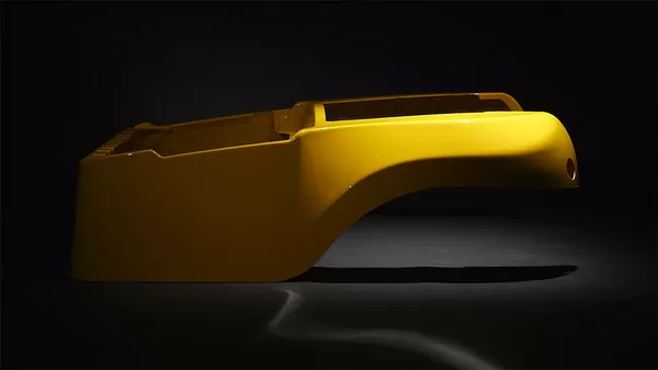
Hollow plastic parts are everywhere in industrial equipment: machine enclosures that need stiffness without mass, air ducting, double-walled covers, doors and panels on mobile equipment. When a single formed shell cannot deliver that stiffness, the usual fallback is two half-parts joined with fasteners — and that inherits leak paths, hardware cost and tolerance stack-up at every joint. Twin sheet thermoforming takes a different route: two heated sheets, one welded part. This article explains how the process works, where it makes engineering and commercial sense, which materials and standards govern it, and which failure modes to check before committing to tooling.
- Twin sheet forming heats two sheets at the same time and fuses them along a controlled weld line, producing a closed, hollow heavy gauge part.
- The main payoff is stiffness-to-weight: a hollow box section outperforms a flat shell of the same mass in bending and torsion.
- Wall thickness is engineered per surface; each side can use a different gauge and, with validation, even a different material.
- ABS, HDPE, PP, PC/ABS, ASA and PP/GF cover most applications; flammability and ingress-protection standards drive selection for electrical enclosures.
- First article approval proves a setup, not a process — weld cross-sections, thickness maps and a pilot run are what prove volume readiness.
- Tooling means two matched mold halves plus trim fixtures, so weld-line placement and trimming strategy must be settled during design.
What Is Twin Sheet Thermoforming, and When Is It the Right Choice?
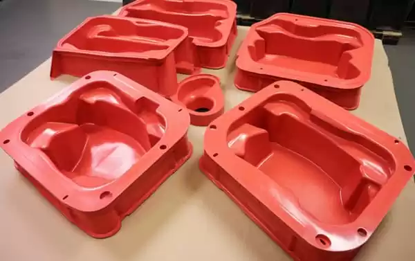
Twin sheet thermoforming forms two heated plastic sheets at the same time, one against each half of a matched mold set, then fuses them along a defined weld line under vacuum and platen pressure. The result is a closed, hollow part with box-section stiffness. It is the right choice when a product needs rigidity, internal channels or double-walled impact resistance that a single formed shell cannot deliver without added assembly work.
Within the vacuum forming family, single-wall heavy gauge forming is the workhorse for housings, covers and trays: an open profile with strong detail on the mold side. Twin sheet forming adds a second sheet and a continuous weld, converting an open shell into a closed structural section that behaves closer to a fabricated box beam than to a tray. On a long machine shroud or a large door panel, that difference appears immediately as torsional rigidity, and as somewhere to hide fasteners and wiring inside the cavity.

Two engineering situations usually justify the second sheet. The first is stiffness-to-weight: a hollow section resists bending and torsion far better than a single-curvature wall of equal mass, which matters for large covers, doors and structural panels. The second is sealed or semi-sealed function: ducting, flotation and insulated panels all depend on the continuity of the weld line. If your part is small, open-backed and lightly loaded, stay with single-wall forming; if it is large, load-bearing or must not leak, twin sheet is the default candidate. For a broader map of the forming family, start with the vacuum forming overview.
How Does the Twin Sheet Forming Process Work?
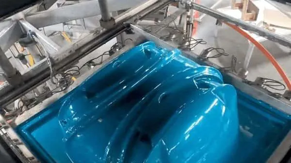
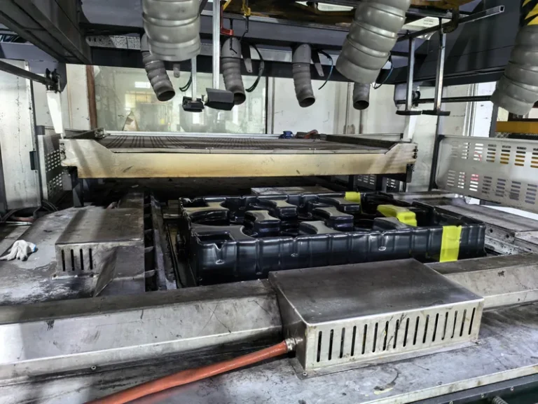
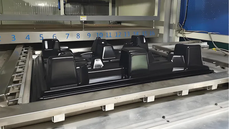
Two clamped sheets are heated at the same time, then moved between upper and lower mold halves. Vacuum draws each sheet onto its mold surface while the platens press the sheets together along a controlled weld line, fusing them into one part that cools in the tool before trimming.
Sheet selection and heating. Both sheets must reach forming temperature in the same window. If the gauges differ — a deliberate choice when a 5 mm structural side is paired with a 3 mm cosmetic side — oven zoning and heating rates have to be balanced so neither sheet sags past its limit. As a rule of thumb, heavy gauge forming pushes the sheet surface well above the material’s heat deflection temperature1 before forming; exact setpoints depend on material, gauge and machine.
Forming and welding. Vacuum in the range of roughly −0.08 to −0.095 MPa, depending on pump capacity and tool sealing, draws each sheet into full contact with its half. Platen force then compresses the mating surfaces along the weld line, where still-hot polymer interdiffuses and fuses. Weld quality decides whether the part behaves as one structure or as two loosely joined shells, so weld-line width, surface temperature and dwell pressure are the parameters to lock down during development.
Cooling, demolding and trimming. The twin sandwich — commonly 6 to 10 mm of combined wall — cools against the mold surfaces, and that total thickness largely sets cycle time. After demolding, a 5-axis trimming centre follows the forming tool’s trimmed outline datum; on twin sheet parts the same trim pass opens ports, inspection windows and mounting features through both walls. The full sequence is covered in more detail in this step-by-step heavy gauge forming walkthrough.

ZetarVac runs more than 20 vacuum forming and thermoforming machines, processing sheet from 0.5 to 15 mm thick with a maximum forming length of about 2,500 mm, followed by 5-axis CNC trimming of formed parts. For a twin sheet program, both sheets can be formed and trimmed on one floor, which removes the coordination risk of splitting the forming step and the trim step between suppliers.
Which Materials and Standards Apply to Twin Sheet Parts?
Most twin sheet industrial parts use ABS, HDPE, PP, PC/ABS or ASA, selected for a combination of stiffness, impact strength, weathering resistance and flammability. The governing standards follow the application: electrical enclosures pull in flammability and ingress-protection classifications, while structural panels are judged on tensile and flexural properties.
Material selection logic. ABS and PC/ABS are the defaults for equipment housings and machine guards, combining reliable formability with impact performance. HDPE and PP suit chemical resistance, tanks and material-handling parts, and PP/GF adds stiffness where the part works as a structural member. ASA holds colour and gloss outdoors, which matters for automotive exterior panels and outdoor equipment covers, while TPE can serve as a soft layer where a seal or liner is required. Because the two sheets weld to each other, material pairing is part of the design: two sheets of the same family weld far more predictably than a mismatched pair, and any cross-family combination needs trial validation.
Standards worth knowing. For parts used as electrical equipment enclosures, UL 746C frames the requirements for polymeric materials in that duty, and UL 942 supplies the flammability classification — the standard grades how a plastic specimen burns and self-extinguishes, and the enclosure must meet the level the end product calls for. Stiffness and strength claims for formed panels are normally backed by tensile data measured to ISO 527-2, the standard tensile test run on plastic sheet. Where a cover must resist dust and water, the IP code defined by IEC 605293 sets the ingress-protection levels the finished enclosure has to demonstrate.
The plant’s material library already covers the grades that matter for hollow industrial parts — ABS, HDPE, PP, PC, PMMA, PC/ABS, ASA and PP/GF — across trays, enclosures, automotive interior and exterior parts, and industrial structural components. Sourcing both sheets of a twin sheet pair from proven forming grades lets weld compatibility be reviewed at the design stage instead of discovered on the machine.
Where Twin Sheet Design Wins — and Where It Does Not
The clearest win is structure. A closed hollow section gives the part bending and torsional stiffness that a flat or single-curvature wall cannot match at the same weight, and the cavity doubles as space for wiring, insulation or floatation. A continuous weld also removes the fasteners, gaskets and leak paths that a two-piece bolted design carries along every joint line. For equipment shrouds, doors, ducts and structural panels, those two effects usually outweigh the longer cycle time.
| Attribute | Twin sheet forming | Single-wall heavy gauge | Pressure forming |
|---|---|---|---|
| Part geometry | Closed, hollow sections | Open shells and trays | Open shells with sharper detail |
| Stiffness-to-weight | Highest — box section | Moderate | Moderate |
| Weld line | Yes, design-critical | None | None |
| Two materials or gauges per part | Yes, with validation | No | No |
| Typical cycle time | Longest — two sheets heat and cool | Shorter | Shorter |
| Best fit | Large covers, ducting, structural panels | Housings, guards, trays | Cosmetic front panels |
The honest limits sit on the other side of the ledger. Deep draws still thin the sheet, so extreme pocket depths fight the process. The cavity must vent, or trapped air keeps the sheets apart. And because the weld line is only as strong as the temperature and pressure at the moment of fusion, weld placement on flat, accessible flanges — not on sharp corners — is a design rule, not a preference.
"Twin sheet forming produces a part with uniform wall thickness on every surface."False
Both sheets start at uniform gauge, but each wall thins where it draws deep into its mold half, so corners and pockets end up measurably thinner than flanges. Writing thickness as uniform into the drawing sets up rejected first articles and avoidable disputes.
"Wall thickness must be specified per surface, with tolerances tied to draw depth."True
Treating each side as its own formed surface matches how the process behaves: flanges stay near nominal gauge while deep draws thin. A per-surface thickness map agreed before tooling gives both parties an objective acceptance basis.
One more design consequence is worth stating: since the two halves are formed independently, internal ribs, standoffs and local reinforcements can be built into either half where they matter, instead of being added as separate hardware later.
What Goes Wrong in Twin Sheet Parts — and How Do You Catch It?
The three failure modes that appear most often are weak or incomplete welds, trapped air between the sheets, and local over-thinning at deep draws. All three are detectable before production with sectioning, leak testing and thickness mapping, which is why they belong in the qualification plan rather than in the complaint file.
Weld defects. A weld line that is too cool, too narrow or contaminated produces a part that survives handling but delaminates under load or vibration. Moisture-sensitive materials such as ABS and PC need properly dried sheet, because absorbed water flashes to steam at forming temperature and leaves voids along the weld. Check by cutting weld-line cross-sections from trial parts and by peel-testing sample welds.
Trapped air and bridging. If the cavity between the sheets cannot vent, residual air keeps the sheets apart and the weld line never closes over its full length. Tooling needs engineered vent paths that reach the last point of contact, and early trials should confirm complete sheet contact through section cuts or ultrasonic inspection.
Thinning and warpage. As in every thermoforming operation, deep draws thin the sheet locally; on twin parts, asymmetric thinning between the two halves can also pull the part out of flat as it cools. A thickness map taken by ultrasonic gauging across a defined grid, plus flatness checks after full cooling, catches both conditions before parts reach assembly.
"Once the first twin sheet article passes inspection, the process is ready for volume."False
A first article proves the tool, the sheet set and the setup on one part, on one day. It says nothing about cycle-to-cycle stability of sheet moisture, oven balance and weld temperature — which is precisely what drifts in production.
"Volume readiness comes from a pilot run that repeats the same checks across consecutive shots."True
Repeating weld cross-sections, thickness maps and dimensional checks over a defined quantity of parts turns a successful first article into evidence of capability. Agreeing on that scope before tooling kick-off keeps both the schedule and the acceptance criteria honest.
Tooling, Tolerances and What to Confirm Before Quoting
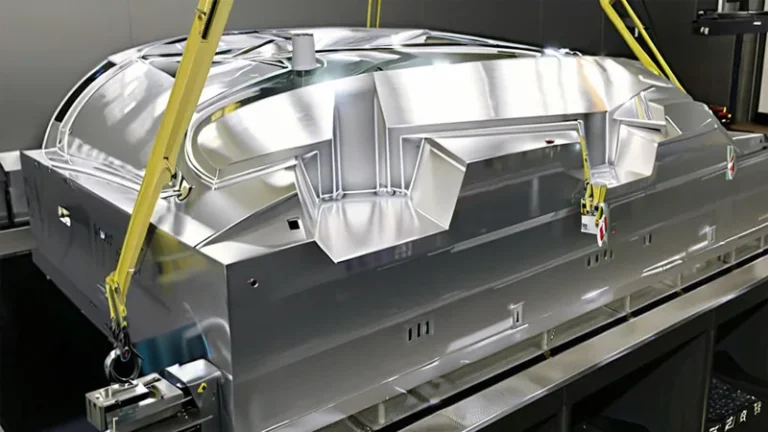
A twin sheet program needs upper and lower mold halves held in alignment, venting that reaches the cavity, and a weld line machined to the agreed width. Because the trimmed outline follows the forming tool, trim fixtures are planned together with the molds rather than improvised afterwards. Working through a DFM checklist for heavy gauge thermoformed parts and molds4 before steel is cut catches most weld-line, venting and draft issues at the stage where changes are cheap.
Tolerances deserve the same realism. Forming moves a heated sheet onto a mold, and shrinkage, thinning and warp act across the whole panel, so formed surfaces carry functional tolerances rather than machined-part values. Tight limits belong on trimmed features referenced to the tool datum, and the drawing should identify which features those are. Splitting the drawing this way also makes quotations faster, because trim operations can be priced against the features that actually carry critical limits.
"A twin sheet enclosure can hold machined-part tolerances across its full two-meter length."False
Shrinkage, thinning and warp accumulate over the whole panel, so a blanket tight tolerance across two meters is not a forming outcome. Critical dimensions belong on trimmed, datum-referenced features, and the rest of the drawing should carry functional tolerances.
"Critical dimensions should be called out on trimmed features, with formed surfaces given functional tolerances."True
This split matches where the process can hold control and where it cannot. It shortens quotation as well, because trim operations can be priced against the features that genuinely carry tight limits.
Finally, confirm what a quotation actually includes: tooling scope, trim fixtures, first article inspection and the qualification tests discussed above. Asking these questions during supplier selection — when the buyer is ready to compare suppliers — is far cheaper than discovering scope gaps after pilot parts arrive.
The plant supports prototyping, small batch and large batch production, with a reference monthly capacity of about 100,000 to 200,000 pieces across more than 45 production lines. For a buyer comparing twin sheet forming against a two-piece assembly, prototype weld-line iterations can run on the same equipment family planned for volume.
FAQ
Can one twin sheet part combine two different materials?
Yes, and it is one of the process’s genuine strengths: a structural ABS half welded to a weatherable ASA half, or a rigid side paired with a TPE liner layer, are realistic configurations. The materials must have compatible melting ranges and weld behaviour, so pairings are validated in trial shots before tooling is finalized.
How thick can twin sheet walls be?
Heavy gauge twin sheet work commonly uses individual sheets in the 2 to 8 mm range, giving a combined wall of roughly 4 to 15 mm depending on the design. The practical ceiling depends on machine heating and pressing capacity as much as on material; the equipment at ZetarVac processes sheet from 0.5 to 15 mm with forming lengths up to about 2,500 mm.
Is the weld line a weak point?
A properly made weld fuses the two sheets into one continuous polymer joint, and the part behaves as a single structure; a cold or contaminated weld will delaminate under load. That is why weld-line width, sheet temperature and platen pressure are fixed during development and then verified with cross-sections and peel tests during trials.
Is twin sheet forming economical at low volumes?
Tooling is two mold halves, so unit economics improve with volume, but the process supports prototyping, small batch and large batch production. At low volumes, simplified mold construction and fewer cosmetic surfaces keep tooling cost proportionate while still eliminating the fasteners and leak paths of a two-piece design.
What should I send for a twin sheet feasibility review?
A 3D model or 2D drawing of the assembly you want to replace, the service environment — indoor or outdoor, temperature, impact, chemical exposure — the annual volume, and any enclosure ratings the part must meet. With those inputs, weld-line placement, gauge split and trimming strategy can be assessed before any tooling commitment.
If you are weighing a twin sheet design against a two-piece assembly, the practical next step is a drawing review: send your drawings and target environment, and talk to an engineer about weld-line placement, gauge selection and trimming strategy through the China vacuum forming manufacturer page, or first review the full service scope.
-
HDT: Heat deflection temperature, the temperature at which a plastic bar deflects a specified amount under a defined flexural load, used to compare the heat resistance of plastic sheet and formed parts. ↩
-
UL 94: The Underwriters Laboratories flammability standard that classifies how plastic materials ignite, burn and self-extinguish, commonly required for electrical equipment enclosures. ↩
-
IP code: The ingress-protection rating system defined by IEC 60529, classifying how well an enclosure keeps out dust and water. ↩
-
DFM: Design for manufacturability, the practice of reviewing a part design against process constraints before tooling is committed. ↩