Mold cavity geometry is the biggest single lever in heavy-gauge thermoforming tooling. It sets how the heated sheet stretches, where material accumulates, and how much machining the part needs after forming. Buyers routinely ask how many cavity types a thermoforming machine actually supports. The short answer: two fundamental geometries — male and female — plus a set of engineered combinations built on them. This article explains each type, the wall-thickness behavior it produces, how cavity count and mold material change the economics, and what to verify before releasing a mold into production.
- A thermoforming machine uses two fundamental cavity geometries: the male (positive) mold and the female (negative) cavity.
- Matched male-female molds and plug-assist setups are engineered extensions of these two basics, not separate families.
- Male molds usually give more predictable wall distribution on deep draws; female cavities preserve outside-surface detail.
- Cavity count trades per-part cycle economics against webbing risk, sheet width and trimming capacity.
- Mold material — machined aluminum, cast aluminum, composite or plaster — should follow cavity complexity and production volume.
- Wall thickness is designed into the cavity through draft, radii and draw ratio, then confirmed on first articles.
What Are the Two Fundamental Mold Cavity Types?
A thermoforming machine works with two fundamental cavity geometries. A male (positive) mold is a raised form the heated sheet drapes over, so the inside surface of the part is shaped directly by the tool. A female (negative) cavity is a recessed pocket the sheet is drawn into, so the outside surface picks up the tool detail. Every other arrangement in vacuum forming is a variation built on these two.
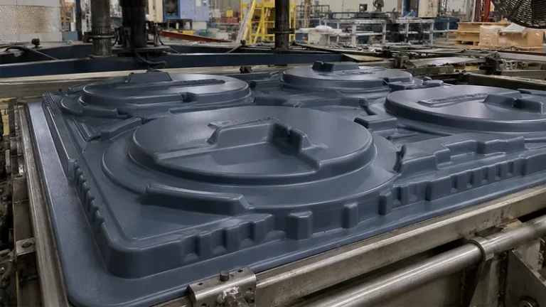
Male (positive) molds. In drape forming, the clamped sheet is heated and lowered over the raised tool; vacuum pulls it tight against the form. Because the sheet touches the mold peak first, material stretches progressively down the sides. Corner thinning concentrates at the base radii, so the designer compensates with generous radii and draft angles rather than accepting whatever the sheet does. Male tooling also tolerates higher draw ratios, which is why deep trays, equipment liners and machine housings are commonly formed this way in heavy-gauge work.
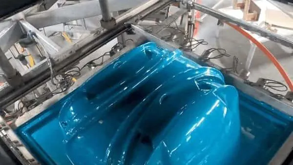
Female (negative) cavities. Here the sheet seals across the mold opening and is drawn down into the pocket. The outside of the part lands against the tool, so texture and sharp detail transfer to the cosmetic surface. The trade-off is wall distribution: the bottom and inside corners of a deep pocket form last and thin the most, and wide flat openings invite webbing across the mouth. Female cavities are the default when outside appearance matters more than maximum depth — outer covers, panels and containment trays.
Engineered combinations. Plug assist drives a mechanical plug into the sheet before vacuum is applied, pre-stretching material toward the pocket bottom so a female cavity can form deeper, more even parts. Matched male-female molds close on the sheet from both sides and are used where thickness control or rib definition must be exact. Pressure forming adds air pressure on the vacuum side and is chosen when cosmetic texture or crisper detail is needed; the cavity geometry itself is still either male or female.
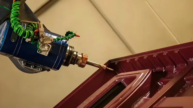
| Attribute | Male (positive) mold | Female (negative) cavity | Matched male-female |
|---|---|---|---|
| Tool contact surface | Inside surface of part | Outside surface of part | Both surfaces |
| Wall distribution on deep draws | More predictable | Corners thin at pocket depth | Most controlled |
| Practical draw ratio | Higher | Moderate | High, with plug assist |
| Tooling cost | Lower | Moderate | Highest |
| Typical heavy-gauge parts | Trays, housings, liners | Covers, panels, display forms | Precision structural parts |
"A female cavity always produces more uniform wall thickness than a male mold."False
The opposite is usually true on deep draws. In a female pocket the sheet bridges the opening first and the bottom corners stretch last, so they thin unpredictably, while a male mold drapes the sheet progressively and keeps distribution inside a predictable band.
"Male molds are the safer default for deep-draw heavy-gauge parts."True
Draping over a positive form stretches the sheet in controlled stages, so corner thinning stays within a known range. The designer can then set the nominal gauge against the thinnest allowed section instead of gambling on pocket corners.
How Does Cavity Design Control Wall Thickness on Deep Draws?
Cavity geometry sets wall distribution before the first sheet is ever heated. The main levers are draw ratio, draft angle, corner radii and vacuum hole placement, with plug assist added on deep draws. Each lever is chosen against sheet gauge and part depth at design time, not corrected afterwards.
The dominant variable is the draw ratio1 — the depth of the part relative to its smallest opening dimension. As a common engineering range, deep-draw cavities are kept to moderate ratios unless plug assist is added, because every increase in depth multiplies corner thinning. Draft angles are the second lever: male molds typically need roughly 2° to 5° of draft on vertical walls so the cooled part releases without distorting, and the exact figure depends on material shrinkage and depth.
Radii and vacuum placement do the quiet work. Tight inside corners locally freeze the sheet and create thin spots, so heavy-gauge cavities use radii scaled to the sheet gauge — thicker sheet demands larger radii. Vacuum holes are concentrated where the sheet contacts last, such as pocket corners and the base of deep forms, so the final stretch is pulled evenly instead of in bursts.
Cooling design is part of the cavity, not an afterthought. Uneven mold temperature warps panels and locks in residual stress, and the channel layout should follow the cavity geometry rather than the easiest drilling path. For a closer look at that interaction in thick sections, review this guide to mold cooling channels in thick-wall thermoforming.
ZetarVac processes sheet from 0.5 mm to 15 mm thick with a maximum forming length of about 2,500 mm. For cavity design that means gauge and envelope must be chosen together: deep cavities in thick sheet need larger radii, more draft and longer cool times, while the 2,500 mm forming length sets the practical ceiling on how large a single cavity can be.
Which Mold Material Fits Each Cavity Type?
Match the material to volume and detail. Machined aluminum suits production cavities, cast aluminum fits large or textured forms, and plaster or composite tooling covers prototypes and bridge volumes. Cost, heat conduction and tool life move together across that ladder.
Machined aluminum is the workhorse for production cavities. It machines to tight detail, conducts heat well for consistent cycle times, and survives long production runs. Most male plugs and female pockets for heavy-gauge production are cut from aluminum block or plate, then polished or textured where the part surface requires it.
Cast aluminum suits larger cavities where machining a full block would be wasteful. Casting captures texture economically and reaches large form sizes at reasonable cost, but the mold needs slightly more draft and porosity control, and surface detail is less crisp than a machined pocket.
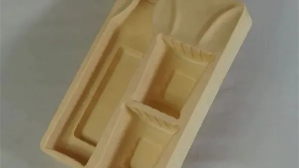
Plaster and composite tooling fill the front of the project. These cavities let designers prove geometry, draft and styling on real material before committing to metal. They form limited part quantities, but they move revisions from weeks to days. For the trade-offs in detail, see this overview of plaster thermoforming molds.
A practical sequence is to prototype in plaster or composite, cut bridge or pre-production tooling in cast aluminum, and release the production cavity in machined aluminum once the geometry is frozen. The same cavity geometry can migrate across materials as volumes grow.
How Many Cavities Should a Heavy-Gauge Mold Have?
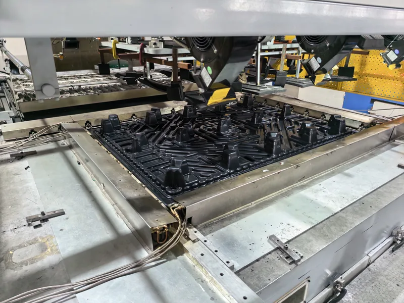
There is no fixed number. Large parts such as equipment housings and machine covers run single-cavity because the part already fills the sheet, while smaller parts go multi-cavity to amortize each cycle. The ceiling is set by sheet width, webbing risk and trimming capacity — not by the forming machine.
Spacing and webbing set the practical limit. Cavities placed too close together let the sheet bridge and fold between them2, and folds between pockets mean scrap parts and slower vacuum. A usable layout keeps enough margin between cavities for the sheet to seal at the clamp frame and stretch without interference, while still using the sheet width efficiently.
Downstream capacity matters as much as the forming cycle. Each added cavity multiplies trimming and inspection load, so a layout the trim centre cannot feed efficiently simply moves the bottleneck one station downstream.
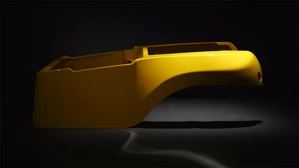
Formed parts at ZetarVac are trimmed on a 5-axis CNC centre, and the trimmed outline follows the forming tool. Cavity count and layout therefore have to be fixed together with the trimming fixture plan — adding cavities without a matching trim path creates registration and handling problems that surface after forming, not during it.
Treat layout as an iteration, not a one-shot decision. A single-cavity prototype reveals webbing and thinning patterns while they are still cheap to fix; the same faults discovered on a finished multi-cavity block mean re-machining and re-balancing across every pocket at once.
"Doubling the number of cavities always halves the cost per part."False
The cycle gain only holds if sheet width, heating uniformity and trimming capacity actually support the extra cavities. Tightly packed heavy-gauge layouts often trigger webbing between parts and force slower vacuum and cool times, so the saving shrinks or disappears entirely.
"Cavity count should be set from part size, sheet width and trim strategy together."True
A layout pays off only when the formed sheet uses its width well, webs stay out of the gaps, and the trimming centre can process the full plate without becoming the constraint. Reviewed as one decision, these factors decide whether multi-cavity tooling earns its cost.
How Do You Verify a Mold Cavity Before Production?
With a first-article check: a dimensional report against the part drawing, a wall-thickness map at the thinnest predicted zones, vacuum integrity and a visual scan for webbing inside the cavity footprint. Material-level tests back the geometry where the application demands it.
The thickness map matters most. Pocket corners on female cavities and base radii on male molds are where the sheet thins first, so spot measurements there confirm whether the nominal gauge still clears the minimum wall after forming. Measurements are taken on cooled parts, since residual heat masks real dimensions.
Material-level tests close the loop. Where a formed panel acts as a structural element, flexural stiffness is validated to ASTM D7903, the standard test method that defines how flexural properties of plastics are measured under bending, and it is the reference for confirming that a formed enclosure wall holds its shape under load. For equipment covers and housings, flammability is screened to UL 944, the standard that classifies how plastic materials extinguish after flame exposure, and many formed enclosures specify a rating before the cavity design is released.
For a structured tour of the tooling side — cavity types, materials and construction choices — continue with this overview of thermoforming mold types.
FAQ
Is a male mold always cheaper than a female cavity?
Not automatically. Polarity alone does not decide cost; size, surface detail, texture and cooling complexity do. A small female pocket with deep texture can cost more than a large plain male form. As a rule of thumb, male tooling is simpler to machine and easier to modify, which keeps cost and lead time lower for comparable detail.
Can one thermoforming machine run both male and female cavities?
Yes. The machine supplies clamping, heating, vacuum and — where fitted — plug assist or pressure. Male and female tools mount on the same platen, and switching between them is a tooling change, not an equipment change. That flexibility is one reason a single vacuum forming cell can cover both housings and trays.
What is plug assist, and when does a cavity need it?
Plug assist is a mechanical helper shaped roughly like the part that pushes the heated sheet into a female cavity before vacuum is applied. It pre-stretches material toward the bottom so corners do not thin out. Deep pockets, multi-cavity trays and parts with strict minimum-wall requirements are the usual triggers.
Does cavity count affect mold lead time?
It does. Each added cavity adds machining, debugging and first-article work, and multi-cavity blocks usually need more iteration to balance vacuum flow and wall distribution across all pockets. For tight schedules, a single-cavity prototype mold that proves the geometry first is often the faster path to stable production.
Where can I keep learning about heavy-gauge mold design?
Start with process and material basics, then go deeper on tooling: how cavity polarity changes wall distribution, how mold material choices follow volume, and how trimming strategy constrains cavity layout.
Next step: to keep learning before you compare suppliers, explore the ZetarVac vacuum forming guide — it walks through heavy-gauge thermoforming from sheet selection to finished, trimmed parts — or review the full service overview to see how the complete manufacturing scope fits together.
-
Draw ratio: The ratio of a formed part’s depth to its smallest opening dimension at the mold line; higher draw ratios demand more careful cavity geometry and often plug assist. ↩
-
Webbing: Folds or bridged wrinkles of sheet material that form across wide openings or between closely spaced cavities when the sheet contacts the mold unevenly during vacuum forming. ↩
-
ASTM D790: Standard test method for flexural properties of plastics, used to validate the stiffness of formed panels and enclosure walls under bending load. ↩
-
UL 94: Standard for the flammability of plastic materials, classifying how specimens extinguish after flame exposure; commonly required for formed equipment enclosures. ↩