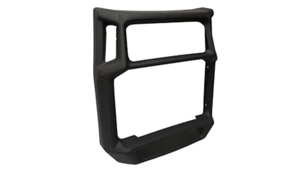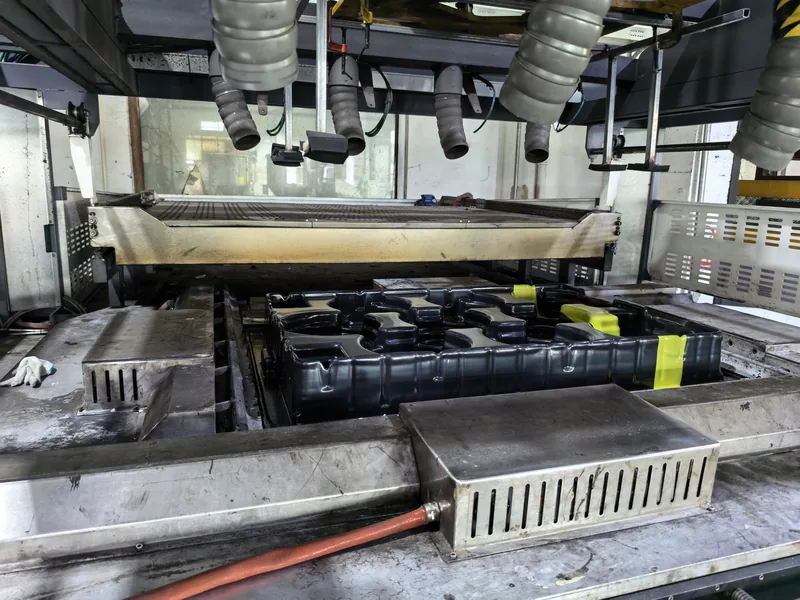
Pressure forming occupies a specific slot in the heavy-gauge thermoforming toolbox: it delivers the cosmetic surface quality that plain vacuum forming leaves on the table, without the tooling cost and lead time of injection molding. For equipment housings, bezels, guard covers and display covers that need defined edges, legible logos and durable texture, the added air pressure is often the difference between a part that looks molded and one that looks formed. This article walks through how the process works, where it earns its premium, and which parameters and checks decide whether a pressure-formed part ships clean or comes back for rework.
If you want the broader context of both forming methods first, the ZetarVac vacuum forming guide covers the fundamentals.
- Pressure forming is thermoforming with positive air pressure added on top of vacuum, commonly in the rough range of 3–7 bar depending on material, sheet gauge and machine class.
- The benefit is detail transfer: tighter corner radii, crisper texture, legible logos and vents that vacuum alone blurs out on stiffer resins.
- Tooling cost sits between vacuum forming and injection molding because the mold needs a sealing frame and a pressure box rated for several bar.
- Sheet temperature, mold temperature, the vacuum-to-pressure sequence and cooling time interact; adjusting one without re-checking the others moves warp and detail definition together.
- Wall thinning at deep draws follows predictable geometry, so design draft angles and radii around it instead of demanding uniform gauge everywhere.
- Enclosure validation normally hinges on tensile, heat deflection and flammability data from the formed sheet, not on visual approval alone.
What Is the Pressure Forming Process?
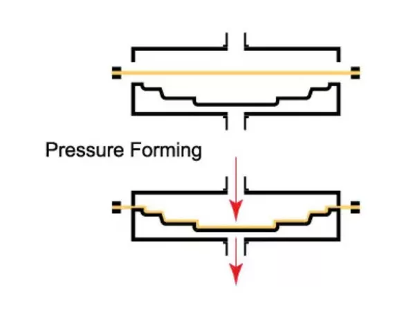
Pressure forming is a heavy-gauge thermoforming variant in which a heated plastic sheet is sealed over a mold, drawn down by vacuum from below and pressed against the tool from above by compressed air, commonly in the rough range of 3–7 bar depending on the machine and material. The added pressure drives the sheet into fine mold detail, producing sharper corners, crisper surface texture and better cosmetic definition than vacuum forming alone.
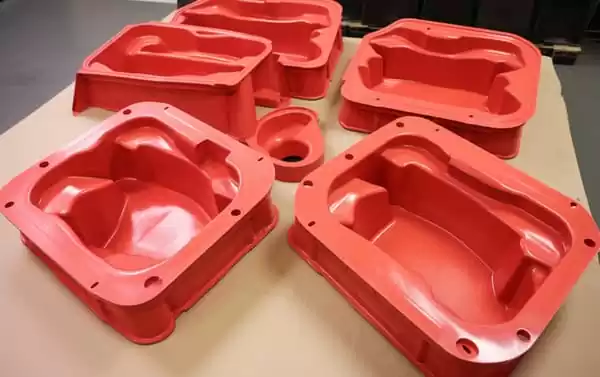
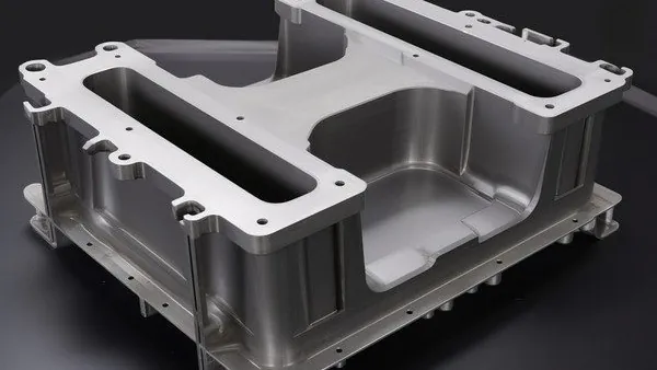
The hardware looks like a vacuum forming machine with two additions. A clamping frame seals the heated sheet against a pressure box above the mold, so the compressed air acts on the full sheet area instead of leaking around the edges. Tooling is usually machined aluminum, often with fine vent holes drilled behind the detail you want to pull in. Because the pressure box must hold several bar against a heated, flexible sheet, the sealing surface, gasket condition and clamping force all become process variables that a plain vacuum cell never has to manage.
How Pressure Forming Differs From Vacuum Forming
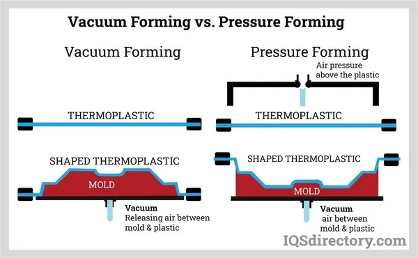
The physics difference is force. Vacuum forming relies on atmospheric pressure — about 1 bar — to push the sheet into the tool, and that ceiling limits how far fine detail transfers, especially on stiffer engineering resins and thicker gauges. Pressure forming stacks positive air pressure on top of that, multiplying the available forming force several times. The practical consequences show up in three places: corner radii pull tighter, embossed or engraved texture reads cleanly on cosmetic surfaces, and fine detail such as vents, ribs and molded-in part numbers survives forming instead of washing out.
The trade is tooling scope and cost. A pressure tool needs a sealing frame, a pressure box and disciplined venting, so it runs above plain vacuum tooling in price, though it remains far below the hardened steel work of injection molds. Cycle time gains a little from faster detail formation but mostly behaves like any heavy-gauge forming cycle, dominated by sheet heating and cooling.
| Attribute | Vacuum Forming | Pressure Forming |
|---|---|---|
| Forming force | About 1 bar (atmospheric) | Roughly 3–7 bar added air pressure, material dependent |
| Corner and edge detail | Softened, generous radii | Tight radii, defined edges |
| Texture and logo transfer | Moderate, can wash out | Sharp, reads cleanly on cosmetic faces |
| Tooling scope | Mold only | Mold, pressure box, sealing frame |
| Relative tooling cost | Baseline | Moderately higher, still below injection molds |
| Typical parts | Trays, liners, simple covers | Housings, bezels, guards, display covers |
"Pressure forming is essentially vacuum forming with a bigger vacuum pump."False
The two processes differ in where the forming force comes from: pressure forming adds compressed air above the sheet, not stronger suction below it. That distinction is what lets the sheet replicate fine texture and tight radii that atmospheric vacuum physically cannot drive it into.
"Pressure-formed tools cost more than plain vacuum tools for a structural reason."True
The mold alone does not make pressure forming work; a sealing frame and a pressure box rated for several bar are part of the tooling package. Budgeting for that hardware up front prevents mid-project surprises when quotes arrive.
A side-by-side treatment of both methods, including when each one wins, is available in our vacuum forming and pressure forming comparison.
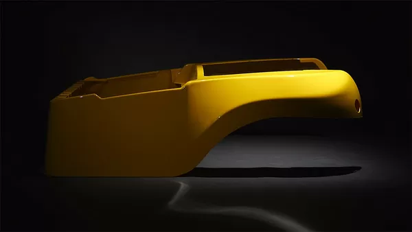
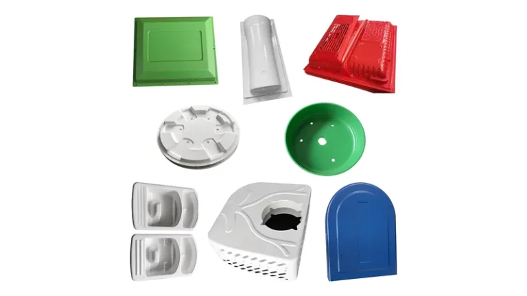
The process justifies its extra tooling wherever a formed face is seen or handled. Equipment housings and diagnostic machine covers use it to hold crisp parting lines and keep mounting bosses visually aligned with the trim edge. Automotive interior trim in ABS or PC/ABS keeps grain definition across curved surfaces. Retail display covers in PMMA hold optical clarity while showing defined edges. Outdoor equipment enclosures benefit from ASA, which resists UV weathering while forming sharply under pressure.
Material choice follows the surface requirement more than the forming process itself. ABS remains the workhorse for housings, cases and guards. PC and PC/ABS bring impact resistance and higher heat capability to electrical equipment covers. ASA holds color and gloss outdoors. PMMA serves displays where clarity matters. Engineering resins such as PA6, PA66 and POM rarely appear in cosmetic forming work because their forming windows are narrow, but they remain part of the heavy-gauge library for structural and precision industrial parts. A fuller material-by-material view sits in our pressure forming plastic overview.
ZetarVac processes sheet gauges from 0.5 to 15 mm with a maximum forming length of about 2,500 mm, running on more than 20 vacuum forming and thermoforming machines across a plant with 45+ production lines. For a buyer, that means large enclosure panels and multi-cavity tray tools can run inside one process window instead of being split across suppliers.
What Process Parameters Control Part Quality?
Four parameter groups dominate: sheet temperature, mold temperature, the vacuum-to-pressure sequence, and cooling time. Get sheet temperature right and the rest of the process becomes forgiving; get it wrong and no combination of vacuum and pressure rescues the part.
Sheet temperature is set relative to the material’s forming window, comfortably above its softening point but below the zone where the sheet sags uncontrollably. Vicat softening data gives a first orientation for where that sag begins.1 Mold temperature decides how fast the contact surface freezes the detail: a cold tool gives crisp texture but risks chill marks, while a warm tool evens out internal stress at the cost of some definition.
Sequencing matters more than most buyers expect — vacuum first to position the sheet against the cavity, then pressure to drive the final detail home — because that order gives the most uniform wall distribution on deep draws. Cooling under pressure locks the texture in before release, and cutting it short is the most common cause of warped panels discovered at trim.
Draw ratio belongs in the design conversation, not just the process one. The ratio of formed depth to part width tells you how much wall thinning to expect at corners and how aggressively the sheet must stretch; deep, small-footprint parts thin out quickly and usually need plug assist or a generously radiated tool.2
"A first article that passes inspection proves the process is stable for production."False
A first article validates tooling geometry and one parameter snapshot at one point in time. Stability only appears once sheet lot variation, heater drift and ambient swings have cycled through the process without detail washout or warp drifting out of tolerance.
"Monitoring sheet temperature and cooling time catches most forming drift early."True
Heater output decay and shortened cooling are the two drift sources that show up first in texture definition and flatness. Tracking them against the approved parameter sheet lets an operator correct a run before scrap accumulates.
None of this is exotic; it is standard heavy-gauge practice on any serious shop floor. What changes with pressure forming is the cost of getting the sequence wrong, because cosmetic detail that fails to transfer in the first 20 parts usually cannot be recovered by running the batch longer.
ZetarVac trims formed parts on a 5-axis CNC centre whose trimmed outline follows the forming tool itself. For pressure-formed housings, that matters because cosmetic edges and texture zones stay aligned with the formed detail instead of depending on manually adjusted trim fixtures.
Which Defects Should You Watch for on Pressure-Formed Parts?
The recurring defect set is webbing between deep features, blisters from overheated sheet, thin corners on aggressive draws, chill marks from a cold tool, and texture washout from low pressure or late vacuum. Each traces back to one of the parameter groups above, which is why a disciplined parameter log shortens troubleshooting dramatically.
Webbing and bridging appear where the sheet spans a wide gap between bosses or ribs and folds onto itself; the fix is usually tool geometry — radii, spacing or a plug assist — rather than process tuning. Blisters point to localized overheating and typically show on the sheet side first. Thin corners are predictable from the draw ratio, and ultrasonic thickness mapping across the part tells you whether the distribution matches design intent or the draw exceeded the tool’s reach.
Chill marks appear as dull patches where the sheet touched a tool spot that was too cold, so they start a mold-temperature conversation, not a reheat one. Texture washout on a pressure-formed face almost always means pressure arrived too late or the sealing frame leaked and the pressure box never reached setpoint.
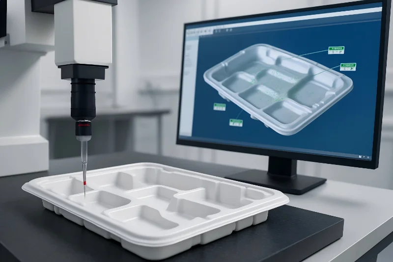
How Do You Qualify a Pressure-Formed Enclosure?
Qualification runs on measured data from the formed sheet, not on visual approval. Tensile properties per ISO 527-2 confirm that forming has not degraded the sheet’s strength beyond the design assumption, since ISO 527-2 specifies the standard tensile test run on thermoformed sheet and molded specimens.3 Heat deflection testing per ASTM D648 establishes the load-bearing temperature ceiling for the panel geometry under flexural load.4
For electrical equipment housings and covers, flammability becomes a procurement requirement: UL 94 classifies the flammability of plastic materials by burn behaviour and is the rating behind many formed equipment enclosures and covers.5 Where a formed cover is specified as part of a protected enclosure, IEC 60529 defines the IP code system that grades protection against dust and water ingress, and the formed part’s seals, cut-outs and trim quality decide whether the assembly actually achieves the claimed code.6 A dimensional layout after 5-axis trimming closes the loop: hole positions, trim edges and flange flatness checked against the drawing.
"Pressure-formed corners hold the same wall thickness as the flat sheet."False
Forming stretches the sheet, and the deepest corners always thin relative to the starting gauge, by geometry rather than by process error. Designs that ignore this end up with corner cracking in impact testing or bosses too weak for the inserts planned into them.
"Corner thinning should be predicted at design, then verified on the part."True
Estimating thinning from the draw ratio lets the designer thicken the starting sheet, enlarge radii or relocate features before tooling is cut. Ultrasonic thickness mapping on first articles then confirms the prediction instead of discovering the problem in the field.
FAQ
How much more does pressure forming cost than vacuum forming?
Tooling runs higher because the pressure box, sealing frame and venting add machining scope, but the gap is modest compared with injection molds. Part prices move with cycle time and scrap rate, so a well-tuned pressure tool can compete on volume runs where cosmetic quality commands the premium. Exact figures depend on part size, gauge and quantity.
Which materials suit pressure forming best?
ABS, PC, PC/ABS and ASA dominate because they combine wide forming windows with the surface quality the process exists to deliver. PMMA serves clear display covers, and HDPE and PP work well for industrial trays and liners where cosmetics matter less. Selection should start from the service environment — impact, heat, UV, chemical exposure — then confirm the grade forms cleanly at the target gauge.
How large can a pressure-formed part be?
Heavy-gauge thermoforming handles sheet from 0.5 to 15 mm thick, and forming lengths up to about 2,500 mm are practical on large-format machines. That envelope covers full-size equipment enclosures, machine covers and large tray tools in a single formed piece.
Is pressure forming suitable for low volumes?
Yes. Prototyping, small batch and large batch production all run on the same process family, and aluminum tooling keeps prototype-to-production continuity. Tooling investment scales with the detail level requested, so early programs often start with simpler tools and upgrade as volumes justify it.
What does pressure forming change about quality documentation?
It adds pressure-system evidence to the standard forming records: sealing integrity, pressure setpoint confirmation and texture-transfer checks join the usual sheet temperature logs, thickness mapping and dimensional layout. Buyers reviewing a supplier’s quality system should ask how pressure parameters are logged, not just whether the parts look right.
To keep exploring how heavy-gauge thermoforming decisions shape a formed part, review the ZetarVac vacuum forming guide, or learn how the team approaches pressure-formed housings and trays as a China vacuum forming manufacturer.
-
Vicat softening temperature: ISO 306 defines the Vicat softening temperature, the temperature at which a flat-ended needle penetrates a plastic specimen under a specified load, used as a practical indicator of where a heated sheet begins to sag. ↩
-
Draw ratio: In thermoforming, the draw ratio compares the formed depth or surface area of a part to its starting sheet dimension, and is used to estimate wall thinning and forming difficulty. ↩
-
ISO 527-2: ISO 527-2 specifies the test conditions for determining the tensile properties of rigid and semi-rigid plastics, and is the standard tensile test run on thermoformed sheet. ↩
-
Heat deflection temperature (HDT): ASTM D648 measures the temperature at which a plastic bar deflects a specified amount under flexural load, giving a practical ceiling for load-bearing use of a formed panel. ↩
-
UL 94: UL 94 classifies the flammability of plastic materials by burning rate, extinguishing time and dripping behaviour, and is the flammability rating required for many plastic equipment enclosures. ↩
-
IP code: IEC 60529 defines the IP code, a two-digit classification of an enclosure’s protection against access to hazardous parts, dust and water. ↩