If you have handled a rigid plastic tray holding instruments, seedlings, or packed machine parts, you have held the output of heavy-gauge thermoforming. This article answers the core question directly: what a thermoforming tray is, how vacuum forming shapes it, which materials suit which duty, what tolerances are realistic, and which failure modes to check before approving a production run.
- A thermoforming tray is made by heating a plastic sheet and drawing it onto a single-sided mold with vacuum; one tool surface defines the part, and the opposite side is free-formed.
- Heavy-gauge trays are structural: sheet is processed from 0.5 to 15 mm, with forming lengths up to about 2,500 mm.
- Material choice drives cost and compliance: ABS for housings and dunnage, PC for impact, PP and HDPE for chemical exposure, PMMA for clarity, TPE for soft liners.
- Corner thinning is the dominant engineering risk; draw ratio, draft angle, and corner radius decide it.
- Put test standards on the drawing instead of adjectives: tensile data to ISO 527-2, heat resistance to ISO 75-2, food-contact compliance to EU 10/2011.
- Tolerance the tool side tightly and the free side loosely; trimmed outlines hold well on 5-axis CNC equipment.
What Exactly Is a Thermoforming Tray?
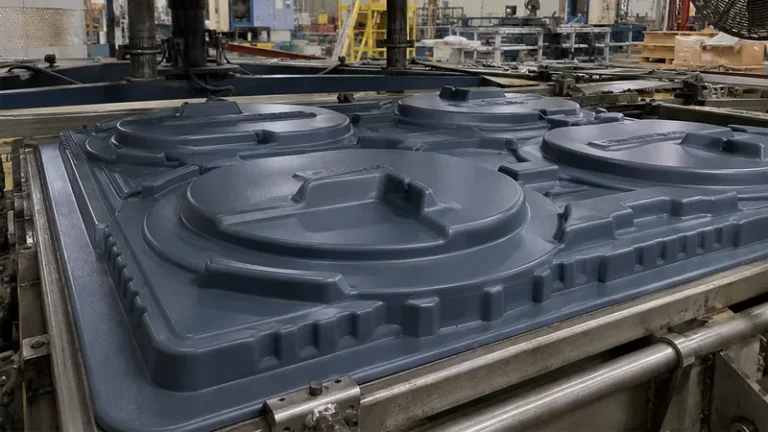
A thermoforming tray is a rigid tray produced by heating a thermoplastic sheet until it softens, sealing it over a single-sided mold, and using vacuum to pull the sheet tightly against the tool surface. After cooling and trimming, the sheet becomes a dimensioned tray with defined cavities, walls, and mounting features.
Two consequences of the single-sided mold matter when you write the drawing. Tool-side surfaces are dimensionally repeatable because they form directly against the mold. Free-side surfaces depend on how the sheet stretches, so their thickness and texture vary more with material and process window. Place critical dimensions on tool-side features wherever the design allows.
Thermoforming also scales differently from processes that inject material into a closed cavity. The tool is machined on one side only, so tooling cost stays moderate, and very large trays remain practical because the forming area is large; on this class of equipment, forming lengths reach about 2,500 mm. The trade-off is that wall thickness is inherited from the sheet and redistributed by the draw rather than set independently at every feature. A related variant, pressure forming, adds compressed air above the sheet to push fine detail and texture into the tool side, but most industrial trays achieve the detail they need with vacuum forming alone.
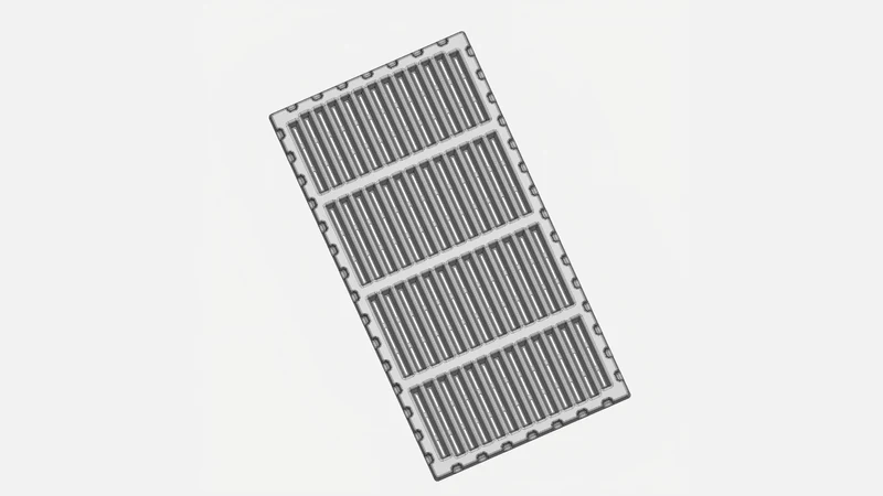
How Does Vacuum Forming Shape a Heavy-Gauge Tray?
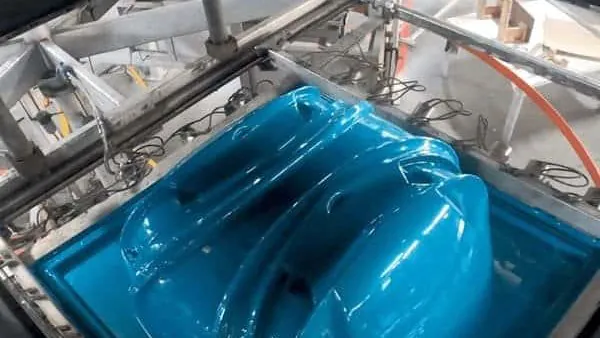
Vacuum forming turns a flat sheet into a tray in five controlled steps, and each step has a process window. Drifting out of any window produces the defects covered later in this article.
Sheet selection and drying: Choose the sheet gauge from the finished wall you need after thinning, not before it. Hygroscopic materials such as ABS, PC, and PMMA absorb moisture that flashes to steam during heating and leaves bubbles in the formed wall, so sheets are dried before forming. Moisture-driven bubbles and splay are treated in depth in our article on bubbles and splay marks in heavy-gauge thermoforming.
Heating: Radiant heater zones bring the sheet into a sag window where it droops visibly but neither tears nor over-thins. Heating is tuned zone by zone so the sag profile is even across the sheet. A hot zone forms thin; a cold zone leaves heavy, under-drawn corners in the same part.
Pre-stretch and forming: Deep cavities need the sheet redistributed before vacuum is applied. A controlled pre-stretch, or billow, or a plug assist pushes material toward the corners ahead of the draw. Vacuum then pulls the sheet onto the tool; the local thinning that results scales with the draw ratio1 of each feature. Deep draws need good vacuum flow and a clean seal, not just maximum vacuum.
Cooling: The part stays on the tool under vacuum until it is rigid enough to release without distortion. Cooling dominates cycle time in heavy-gauge work because thick sheet holds heat, and a part released hot will warp as its skin shrinks over a still-soft core.
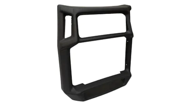
Trimming: The clamped flange and excess material are removed after forming. On modern equipment this happens on a 5-axis CNC centre, so the trimmed outline follows the same geometry as the forming tool.
For a deeper treatment of these process windows, the SPE Thermoforming Division publishes technical resources for forming engineers, including papers on heating, pre-stretch, and tooling practice.
ZetarVac runs more than 20 vacuum forming and thermoforming machines within a plant of 45+ total production lines, processing sheet from 0.5 to 15 mm with maximum forming lengths of about 2,500 mm. For buyers, that range means large industrial trays can be formed as one piece rather than assembled from sections, which removes joints from both the cost model and the failure list.
Heavy-Gauge and Thin-Gauge Trays: The Practical Divide
Heavy gauge describes sheet thick enough that the formed part works as a structural component, commonly about 1.5 mm and above, while thin gauge covers the disposable packaging range. The boundary is practical rather than sharp: what matters is whether the tray must carry load, survive repeated handling, or last through a defined service life.
| Attribute | Thin-gauge tray | Heavy-gauge tray |
|---|---|---|
| Typical sheet | Below about 1.5 mm | About 1.5 to 15 mm |
| Duty | Single-use packaging | Reusable, load-bearing |
| Tooling | Highly cavitated, fast-cycling tools | Single or low-cavitation machined tools |
| Wall control | Thin walls driven by cycle speed | Even walls, material redistributed by the draw |
| Typical examples | Food packs, retail blister packs | Equipment housings, dunnage trays, seedling trays |
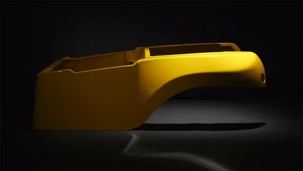
Specify heavy gauge when the tray is part of the product’s operation — equipment liners, machine enclosures, automotive interior parts — or when it must survive repeated logistics cycles. Specify thin gauge when the unit cost of a disposable piece dominates. How cost behaves across that line is covered in our guide to cost control in thermoforming.
"Heavy-gauge thermoforming only pays off at very large production volumes."False
Heavy-gauge tools are single-sided and machined, so their cost sits far below the highly cavitated tooling used in disposable packaging work. Because prototyping, small batch, and large batch production are all supported, heavy-gauge tray programs commonly start at volumes where more cavitated routes would never recover their tooling cost.
"Heavy-gauge tray economics work at low and mid volumes."True
The dominant tooling cost is one machined mold surface, and batch size can be matched to the program stage. A design validated in prototyping can move into batch production on the same tool family without a retooling step, which keeps early programs affordable.
Which Material Should a Thermoforming Tray Use?
Use ABS when you need a tough, cost-balanced structural tray; PC or PC/ABS when impact and heat resistance dominate; PP or HDPE where the tray meets chemicals or moisture; PMMA when clarity sells the product; and TPE as a soft liner combined with a rigid shell. Load, temperature, chemical exposure, and compliance rules make the final call.
| Material | Tray and cover applications | Engineering watch-outs |
|---|---|---|
| ABS | Automotive interior parts, equipment housings, cases, guards | Dries before heating; balanced cost and toughness |
| PC | Clear guards, equipment protection covers, automotive parts | Moisture sensitive; higher forming temperature |
| PC/ABS | Automotive interiors, equipment housings, guards | Blend balances heat resistance and cost |
| HDPE | Industrial trays, equipment liners, storage boxes | Higher shrinkage; warpage control matters |
| LDPE | Thin-wall packaging parts | Limited structural duty |
| PP | Automotive interior parts, trays, packaging, boxes | Warps if cooling is uneven |
| PMMA | Clear covers, luminaires, display parts | Stiff but more brittle than PC |
| TPE | Soft liners, seals | Liner or seal material, not a shell |
Compliance narrows the list quickly. Trays and packaging that touch food must be made from materials and articles compliant with EU 10/2011, the European regulation for plastics intended to come into contact with food, so the sheet certificate matters as much as the mechanical data.
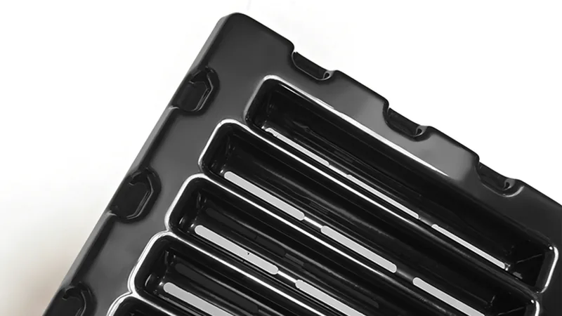
One representative program: an ABS vacuum-formed seedling tray for agricultural seedling raising, built as a heavy-gauge multi-cavity tray with custom tray size, cavity count, and cell geometry. With reference monthly capacity of about 100,000 to 200,000 pieces across the plant, and prototyping through large-batch production supported, cell geometry can be validated in field trials before volumes ramp.
Where Do Thermoformed Trays Fail — and How Do You Check Them?
Most tray defects trace back to wall-thickness redistribution: corners and deep cavities thin out, close features web, and released parts warp as residual stress relaxes. Each defect has a distinct signature, so a structured first-piece inspection catches problems before a batch ships.
Corner thinning: High draw-ratio corners are the thinnest zone in any formed tray. Check them directly by cutting sections or probing with an ultrasonic thickness gauge at the corners and the floor. The design levers are larger corner radii, draft angles of a few degrees, and pre-stretch or plug assist on deep cavities.
Webbing between cavities: When cells sit close together, the sheet bridges between them instead of following the valleys. Increase cavity pitch, deepen the pre-stretch, or redesign the cell geometry; the seedling tray program above shows how far cavity geometry can be customized.
Bubbles and surface marks: Bubbles point to moisture or overheating; surface marks mirror the tool. Drying schedules and clean tool surfaces solve most of it.
Warpage: Large flats bow when cooling is uneven or the part is released hot. Uniform cooling, adequate in-tool cooling time, and flat trimming fix the majority of cases.
Pockmarks and soft detail: Poor vacuum flow, leaking seals, or a dirty tool leave pockmarks and rounded detail. Check vacuum lines and seal quality before blaming the sheet.
None of these checks substitute for a defined release process. A first article2 is the fully inspected initial sample that validates the tool and the process window; it is the reference against which batch output is judged, not a substitute for ongoing inspection.
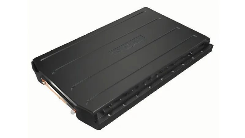
"A first-article-approved tray guarantees the whole production run will match it."False
The first article validates the tool and the process settings on one sheet lot. Sheet gauge drift, heater aging, and ambient conditions still move the process window, so volume output needs periodic wall-thickness checks and agreed re-inspection points.
"First-article approval is the start of quality control, not the end."True
Lock the approved parameters with the sample, then monitor incoming sheet lots and in-process wall thickness at agreed intervals. That combination is what keeps late batches inside the tolerance the first article demonstrated.
What Tolerances and Tests Should a Tray Drawing Specify?
Specify tight tolerances only where the process can hold them: tool-side formed features and trimmed outlines. As starting points for heavy-gauge work, formed dimensions are commonly drawn to about ±1% of the nominal size, trimmed outlines hold closer on 5-axis CNC equipment, and draft angles of 2 to 5 degrees with radii no smaller than the sheet gauge release cleanly. Actual capability depends on material, part size, and draw depth.
Split the drawing into three tolerance zones: tool-side formed surfaces, free-side formed surfaces, and trimmed edges. Tool geometry compensates for mold shrinkage3 as the part cools, so state the zone alongside each critical dimension when you request a design review.
Put standards on the drawing instead of adjectives. ISO 527-2 specifies the tensile test method used to verify the mechanical properties of plastic sheet and formed parts, giving buyer and supplier a shared, reproducible number. Heat resistance is quantified through heat deflection temperature4 tests such as ISO 75-2, which measure when a loaded specimen deflects under flexural load — the property that decides whether a tray holds shape near hot equipment. For clear PMMA covers, total luminous transmittance can be verified to ISO 13468.
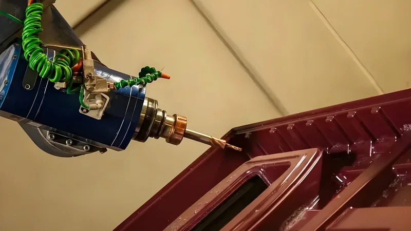
Formed parts are trimmed on a 5-axis CNC trimming centre, and the trimmed outline follows the forming tool. For tray buyers this ties outline accuracy to the tool definition rather than to manual template cutting, which keeps cavity-to-cavity and tray-to-tray consistency stable across a batch.
FAQ: Thermoforming Trays in Practice
What sheet thickness can a heavy-gauge thermoforming tray use?
The lines here process sheet from 0.5 mm to 15 mm with forming lengths up to about 2,500 mm. Structural trays commonly fall between 3 and 8 mm depending on load and span; the right gauge is the one that still meets spec at the thinnest corner after forming.
Is vacuum forming or pressure forming better for trays?
Vacuum forming is sufficient for most industrial trays, including housings, dunnage, and seedling trays. Pressure forming earns its extra tooling cost when the tool side needs sharp texture or fine cosmetic detail, so start with vacuum forming and move to pressure only if the surface specification demands it.
Can a thermoforming tray be used for food contact?
Yes, provided the sheet carries the compliance. Food-contact trays and packaging must use materials compliant with EU 10/2011, so ask for the sheet certification with the material data — the forming process itself does not create food-contact status.
Do suppliers support prototype and small-batch tray programs?
Yes. Prototyping, small batch, and large batch production are all supported, with reference monthly capacity of about 100,000 to 200,000 pieces across the plant. The services overview describes how projects move from design review through production.
How do I validate a tray design before committing to volume?
Combine a split tolerance drawing (tool side, free side, trimmed edges) with sheet data tied to ISO 527-2 and, where relevant, heat and food-contact standards. Then inspect the first article for corner thickness, webbing, and warp before releasing the batch.
To keep digging before you shortlist suppliers, explore the full vacuum forming process guide, or see how a China-based vacuum forming manufacturer runs heavy-gauge tray projects from prototype through batch production.
-
Draw ratio: The relationship between formed part depth or area and the original sheet dimensions; higher draw ratios increase thinning at corners and floors. ↩
-
First article: A fully inspected initial production sample used to verify tool and process setup before volume output is released. ↩
-
Mold shrinkage: The dimensional change of a formed part as it cools after forming, which tool geometry must compensate for. ↩
-
HDT: Heat deflection temperature, the temperature at which a standardized plastic specimen deflects a specified amount under flexural load. ↩