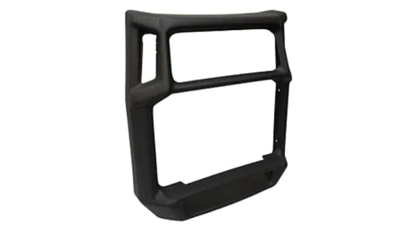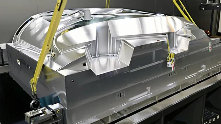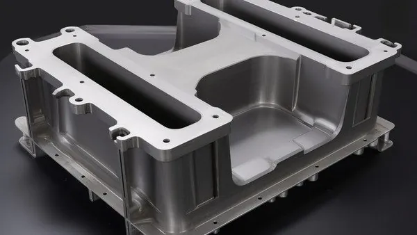
Heavy gauge vacuum forming turns thick thermoplastic sheet — processed from 0.5 to 15 mm on industrial lines — into equipment housings, machine covers, industrial trays and structural parts. Because the sheet carries real mass and thermal inertia, its defects do not behave the way thin-gauge packaging checklists predict. A sagging flange, a web in a deep pocket or a warped cover has a specific mechanical cause, and each one leaves measurable evidence in the finished part.
This guide walks through the defects that actually reject heavy gauge parts in production: what causes them, how to detect them at first article, and what to change on the machine, the sheet or the mold. The goal is practical — when you review a supplier’s first articles, you should know which measurements separate a stable process from a lucky sample.
- Defects concentrate at geometry transitions — corners, deep pockets, flanges — because thick sheet resists stretching and locks in thermal gradients.
- Webbing and bridging are sheet-management problems first: adjust sheet width, heater zoning and plug geometry before blaming the mold.
- Warpage is locked in by asymmetric heating and cooling; clamping a finished part flat cannot remove residual stress.
- Wall thickness is predicted at the quote stage with a draw ratio review, then verified with sectioned measurements on the first article.
- Standards anchor the paperwork: ISO 527-2 ties sheet tensile certificates to part strength, and UL 94 governs flammability for formed equipment enclosures.
- A first article only means something when it is paired with agreed gauges and a documented process window.
Why Do Heavy Gauge Parts Fail Differently?
Because thick sheet resists stretching, heavy gauge thermoforming defects concentrate at geometry transitions — corners, ribs, deep pockets — instead of spreading evenly across the part. The wall cools from both surfaces inward, so thermal gradients lock stress into the section long before trimming. Most rejects trace back to three variables: heater output distribution, mold temperature symmetry and draw depth.
A 4 mm ABS sheet and a thin packaging film fail on different physics. Thick sheet stretches locally rather than uniformly, so wherever the mold demands more extension than the hot sheet can give, the wall thins sharply or the surplus folds. And because a heavy section takes minutes rather than seconds to cool, the last thermal event in the cycle is what the part keeps: uneven heater zones, cold mold corners and unbalanced cooling air all print themselves into the finished part as permanent stress patterns.
The consequence for buyers is simple: defect review on heavy gauge parts should start with the thermal history — heater settings, mold temperatures, cooling time — before anyone inspects the tooling. A part that is thin in one corner and stressed in another usually names the heater zone or mold insert that caused it.
What Causes Webbing and Bridging in Deep Cavity Parts?
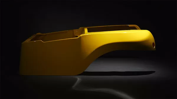
Webbing and bridging form when the heated sheet carries more material than the mold geometry can absorb, so the surplus folds onto itself between two raised features. The cure is almost always geometric and thermal — narrower sheet, zoned heater output, a reshaped plug — not a new mold.
Webbing typically appears between two bosses, along the inside of a long pocket, or where the side walls of a housing meet its top. The hot sheet sags1 between the clamp frames; if sagged material reaches the mold before the vacuum has stretched it evenly over the form, it folds like fabric. Bridging is the same failure in miniature, where the sheet skips a shallow pocket and never contacts its floor.
Draw ratio2 drives the risk. The deeper the draw relative to the sheet width, the less surplus the process tolerates, and past moderate ratios most parts need plug assistance, faster vacuum application and deliberate heater zoning that keeps the deepest features at forming temperature longest. The SPE Thermoforming Division’s troubleshooting references treat webbing the same way — as a sheet-distribution issue before a tooling issue (thermoformingdivision.com).
The correction sequence that works on the shop floor: reduce sheet width so there is no surplus material; re-balance heater zones so mid-web areas run slightly cooler than the features that need stretch; add or reshape a plug to meter material into the cavity; and relocate vacuum holes near the fold lines. Only after that list is exhausted does tooling come under suspicion.
"Webbing in a deep draw means the mold tool is defective."False
Webbing comes from surplus hot sheet folding between mold surfaces, which is a heater, plug and sheet-length problem in the great majority of cases. Ordering new tooling before the forming window is tuned usually reproduces the same defect in a more expensive mold.
"Webbing corrections belong in the process window, not the tooling budget."True
Sheet width, heater zone balance, plug geometry and vacuum timing are all adjustable without cutting metal. Tuning these first isolates the rare genuine tooling fault — an oversized radius that physically traps the sheet, for example — at a fraction of the cost.
Long, deep parts are where this discipline pays off. The same geometry that wins the part — long covers, deep housings — also multiplies webbing risk, so draw ratio and sheet surplus are reviewed at the DFM stage before a mold is quoted. The DFM checklist for heavy gauge thermoformed parts and molds lists the geometry questions that surface this risk early.
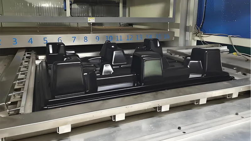
ZetarVac processes sheet from 0.5 to 15 mm with forming lengths up to about 2,500 mm across 20+ vacuum forming machines, so draw ratio and sheet surplus are reviewed before any mold is quoted — long, deep parts are planned, not discovered.
Sag, Blisters and Uneven Wall Thickness
Sheet sag is the oldest control in thermoforming: heat the sheet, watch it droop between the frames, form when the sag reaches target. Sag tells you when the sheet is ready, but it also previews your wall thickness map — areas that sag early and deeply are the areas that will stretch thinnest.
Uneven wall thickness in heavy gauge parts usually comes from three sources: non-uniform heater output across zones, sheet that is at temperature in the center but cooler at the clamp edges, and the order in which surfaces contact the mold. The first surface to touch freezes at nearly full sheet thickness; the last surfaces to contact thin out. On a long industrial cover this is why the same part can measure noticeably thicker at its base than at its top. Where a cosmetic surface has to stay true — a textured or glossy panel, or a pressure forming face — sheet temperature uniformity matters more than raw heater power.
Blistering is a different failure mode: moisture in the sheet flashes to vapor at forming temperature and lifts blisters from the surface. Hygroscopic materials are the usual suspects, and they need drying before forming regardless of how good the certificate looks. Since ISO 527-2 specifies the tensile test method for plastics and is the standard tensile test run on thermoformed sheet and formed part validation, the tensile data on each sheet certificate is the baseline a new lot must match before it enters the process window.
"An unchanged heater profile will form every incoming sheet lot identically."False
Sheet lots differ in moisture content, regrind percentage and flow behaviour, so settings that produced good parts last month can push a new lot out of specification. Moisture that was invisible at goods-in blisters the surface at forming temperature.
"Incoming sheet must be verified against the process window, lot by lot."True
A short sag check on the heater, moisture control for hygroscopic materials and a certificate comparison against the last approved lot catch drift before it becomes scrapped parts. This is also what makes first-article data reusable across batches.
How Do You Control Warpage and Post-Forming Distortion?
Warpage comes from differential shrinkage: one side of the wall freezes before the other, storing stress that releases as the part equalizes to room temperature. Control it during forming — symmetric heating, balanced mold temperature, even cooling — because clamping a finished part flat cannot remove residual stress.
On thick sheet, the mold-side skin cools and freezes first while the free side is still hot and mobile. Demold too early and the core continues shrinking as it cools, pulling flanges up, bowing panels toward the free side and lifting covers off their mounting planes. Fixtures hold geometry while the part finishes cooling, but they manage the symptom; a part that snaps back after fixturing is reporting an asymmetric thermal history, and the correction belongs upstream — heater output on the offending side, mold temperature balance, cooling air distribution or cooling time before demold.
Material selection changes the margin. A formed cover mounted near a heat source will creep back toward a stress-free shape as it approaches its heat deflection temperature3, so room-temperature flatness is not enough; the part needs HDT headroom for its service environment. This is one reason PC and PC/ABS enclosures and ASA outdoor covers are quoted with service temperature in mind, not just forming behaviour.
"Warped parts can be flattened by clamping them after forming."False
Clamping a hot part flat holds it while it cools but does nothing about the stress stored across the wall; distortion typically reappears at trimming or in service. Persistent warpage is an upstream thermal problem surfacing downstream.
"Warpage control belongs in symmetric heating, mold temperature and full cooling before demold."True
Balanced heater output, matched mold surfaces and complete cooling time let the part freeze with low, even stress. Fixturing then serves as a tolerance-holding aid during finishing rather than a permanent crutch.
Surface and Trim Defects: Blush, Marks and Edge Quality
Blush — pale stress marks on formed corners — appears on ABS and other glossy materials when the sheet is formed too cold or stretched over a tight radius. The fixes run in order: hotter sheet, larger radius, faster contact so the surface does not chill against the mold mid-stretch. On textured cosmetic panels, insufficient sheet temperature or pressure also shows up as poor texture definition.
Sheet-side defects are the mill’s signature: surface lines, gels or inclusions that reproduce at the same position and orientation on every part. Map them against the sheet direction, then replace the sheet and tell the supplier where the mark sat in the roll. Forming cannot remove what the sheet arrived with.
Trim quality is where heavy gauge parts are quietly rejected. Dull tooling, wrong feed rates or hand finishing show up as melt-polished edges, hairline cracks on notched corners and distorted holes — and on rigid PC those edge cracks can propagate under impact long after passing visual inspection.
Formed parts are trimmed on a 5-axis CNC trimming centre whose outline follows the forming tool, so trimmed geometry is defined by the tool itself and first-article trim dimensions stay locked when repeat batches run.
For housings and covers these defects are not merely cosmetic. UL 94 classifies the flammability of plastic materials and is the standard behind the flammability requirements many formed equipment enclosures must meet, so an uncontrolled material substitution or a cracked edge can invalidate the rating the enclosure was designed around. In the same way, IEC 60529 defines the ingress protection (IP) code4 that rates enclosure covers against dust and water, and a warped flange that breaks the gasket line turns a rated cover into an unsealed shell.
How Should First Articles Be Inspected and Approved?
A first article is only meaningful if it measures the properties that drift in production: wall thickness at sectioned planes, flatness on defined datums, hole positions after trimming and edge condition. Agree the gauge method before forming, then tie the FAI5 sign-off to a documented process window rather than to a single good part.
| Defect | Typical root cause | Detection method | First correction |
|---|---|---|---|
| Webbing / bridging | Excess sheet, poor heater zoning, plug shape | Visual on deep-draw first article | Reduce sheet width, re-zone heaters, reshape plug |
| Thin corners | High draw ratio, cold forming | Section cut and measure | Hotter sheet, larger radius, plug assist |
| Warpage | Asymmetric heating and cooling | Flatness on surface plate or CMM | Balance heater zones and mold temperature, extend cooling |
| Blisters | Sheet moisture | Visual, surface profile | Dry hygroscopic sheet before forming |
| Blush | Forming too cold, tight radius | Visual on glossy surfaces | Raise sheet temperature, increase radius |
| Trim cracks | Dull tooling, wrong feed rate | Edge inspection, dye check on PC | Resharpen tooling, adjust feed |
The table works only when the process behind it is recorded. Heater zone settings, mold temperatures, vacuum timing and cooling time should ship with the first article, so repeat batches run on locked settings instead of re-deriving them. With 45+ production lines across the plant and reference monthly capacity of about 100,000–200,000 pieces, that discipline is what lets prototyping, small batch and large batch production share one process definition.
For the full process context behind these checks, see our heavy gauge thermoforming overview and the companion vacuum forming process guide.
FAQ
What sheet thickness counts as heavy gauge in thermoforming?
Heavy gauge thermoforming generally refers to sheet thick enough that the part carries structural duties rather than packaging duties — the range where thin-gauge packaging rules stop applying and structural behaviour starts. Our forming lines process sheet from 0.5 to 15 mm, which spans lighter work through heavy structural parts on the same equipment.
Can webbing be fixed without changing the mold?
Yes, in most cases. Sheet width, heater zone balance, plug geometry and vacuum timing are process adjustments, and tooling should only be reconsidered after those have been tuned and the defect still persists.
How is wall thickness distribution checked on a formed part?
By cutting the part at agreed planes and measuring the sections, or by ultrasonic gauging at agreed points. The results are compared against the draw-ratio prediction made at the quote stage, so the buyer sees whether thinning landed where it was predicted.
Which materials handle these defects best?
ABS forms forgivingly and signals trouble with blush; PC needs drying but delivers clarity and impact; PP demands careful cooling to hold flatness; ASA carries outdoor enclosures. Material choice does not eliminate defects — it shifts which ones dominate, which is why the process window is set per material.
What should I send a supplier for a defect review?
Your 3D model and drawings with critical dimensions, the standards the part must meet, photos or physical samples of the rejected parts, and the sheet material and lot if known. With that, an engineer can trace most defects to heater, plug or mold causes within a single review.
When you are ready to compare suppliers for a formed housing, tray or cover, share your drawings with our engineers or review our full forming service scope — send the part and the defects you are seeing, and you will get a cause-and-fix engineering assessment back.
-
Sag: the downward droop of heated plastic sheet between the clamping frames under gravity; sag height is a practical indicator of forming temperature. ↩
-
Draw ratio: the relationship between formed part depth or area and the original sheet dimensions; higher draw ratios predict greater wall thinning. ↩
-
HDT (heat deflection temperature): the temperature at which a plastic test bar deflects a defined amount under a specified flexural load. ↩
-
IP code: the ingress protection rating system for enclosures, classifying protection against dust and water. ↩
-
FAI (first article inspection): documented dimensional and functional verification of the first part produced under production conditions. ↩