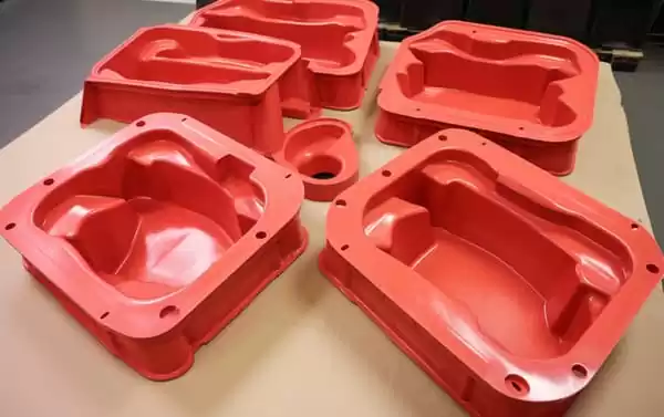

Corners look like a minor drawing detail on a vacuum formed part, yet they decide whether the sheet forms cleanly or fights the tool on every cycle. A sharp inside corner asks hot plastic to stretch into a radius smaller than the material can follow; a rounded corner gives the sheet a path to drape and seat against the mold. This guide explains the physics behind the difference, the thinning you should plan for, where sharp corners are still acceptable, and how to write corner callouts that survive first article inspection.
- An inside corner radius of at least one sheet thickness is the practical floor for vacuum forming; deep draws favor 1.5–2×.
- Sharp inside corners concentrate strain, causing webbing, bridging, and local thinning that can exceed 40% in deep draws.
- Corner radii are machined into the forming tool, so they must be fixed before tooling release, not adjusted after trials.
- Rounded corners seat progressively under vacuum, distribute structural load, and trim more predictably.
- Sharp corners remain acceptable on clamped flanges and trim lines where the sheet is never stretched.
- Radii, draft, and vacuum hole layout work together; specifying one without the others leaves first article results to chance.
Why Do Corners Matter So Much in Heavy Gauge Thermoforming?
Because the corner is where the sheet stretches the most while the vacuum has the least grip. Nearly every forming defect — thinning, webbing, bridging — appears first at the inside corners of a drawn feature.
When a heated sheet drapes over a tool, material flows from the flat clamped areas toward the deepest surfaces. Flat walls and gentle curves receive sheet continuously, but a corner apex is reached last and must be fed by material that has already been stretched. The smaller the radius, the more that final stretch concentrates on a narrow band of plastic. This is why two housings with identical wall specifications can form differently once one is drawn with crisp corners and the other with radiused ones.
Heat distribution plays a role too. Corners are fed by sheet that has traveled the longest distance and cooled the most, so by the time material reaches a deep corner apex it is stiffer than the sheet still sitting over flat areas. Under-heated corners bridge; over-heated flat areas sag. The forming window is the balance between the two, and tight corners shrink that window from both directions.
Gauge amplifies the effect. Heavy gauge thermoforming works with structural sheet rather than thin web material, a distinction the IQS Directory’s thermoforming overview summarizes well. A 10 mm sheet cannot negotiate a 3 mm radius the way a 1 mm sheet can, and the forming window narrows as thickness rises. How far the sheet must travel over the tool — the draw ratio — determines how much strain each corner absorbs before it even contacts the mold surface.1
What Physically Happens at a Sharp Corner During Forming?
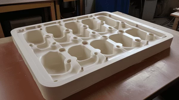
The sheet bridges the corner instead of seating into it. Because the flat walls on either side contact the tool first, the hot material spans the tight radius like a cable, leaving trapped air, a thin stretched apex, or a folded web behind.
Webbing is the visible failure. As the sheet is drawn down, it tends to take the shortest path between two tall features, and a sharp inside corner between them offers no surface to seat on. The excess material folds into a web that must be trimmed away or designed out. Vacuum holes cannot fix this — they only remove air after the sheet has already decided where to lie.2 The remedy is geometric: open the radius, increase the spacing between features, or add a rib that breaks the span.
Thinning is the invisible failure. Even when the corner appears filled, the apex wall is frequently 40% thinner than the nominal sheet in deep draws, which shows up later as a crack initiator under impact or vibration. This is why corner regions deserve their own inspection points on the first article, not just an overall thickness check.
"More vacuum holes will make a sharp corner fill correctly."False
Vacuum only removes trapped air; it cannot stretch material into a radius smaller than the sheet can follow. If the geometry bridges, added hole density changes nothing, and the corner ships thin or webbed.
"Corner geometry must be resolved before the forming tool is cut."True
The radius is machined into the mold surface, so it is the one variable that cannot be tuned at the machine. Trials adjust heat, vacuum timing, and hole layout around the geometry you fixed up front.
In practice, the review point is the drawing review, not the forming trial. If a called-out radius is smaller than the sheet gauge, flag it before tooling starts, because that decision drives everything downstream.
ZetarVac processes sheet from 0.5 to 15 mm, and the same nominal radius means different things across that range: a 3 mm radius is generous on 1 mm ABS but effectively sharp on 15 mm HDPE. Scale every radius callout to the gauge you are actually forming.
How Much Wall Thinning Should You Expect at a Corner?
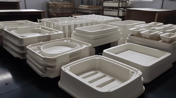
Plan on roughly 20–30% thinning at a generous radius in a moderate draw, and 40% or more at a tight radius in a deep draw. Exact values depend on material, gauge, and draw depth, which is why formed corners are measured, not assumed.
These are engineering ranges for heavy gauge work, not guarantees; the honest way to set them is to cut samples from formed corners and test them. ISO 527-2 specifies the tensile test method for plastics, and running that test on coupons trimmed from a formed corner tells you how much strength the thinning has actually cost the part. Property data measured on flat sheet does not automatically transfer to a biaxially stretched corner.
| Factor | Sharp corner (r < 1 × sheet thickness) | Rounded corner (r ≥ 1–2 × sheet thickness) |
|---|---|---|
| Local wall thinning | High, often 40%+ in deep draws | Moderate, typically 20–30% |
| Webbing and bridging | Likely between tall, close features | Rare with sound vacuum layout |
| Vacuum seating | Air traps at the corner apex | Sheet seats progressively |
| Structural behavior | Notch effect under impact and vibration | Load spreads through the radius |
| Rework risk after trials | High; corners fail first article | Low; geometry forms predictably |
| Best suited for | Clamped flanges and trim lines | Deep draws, housings, trays |
Inspect corners as a separate checkpoint on first articles. Measure wall thickness at the apex and at mid-radius, record the values against the nominal gauge, and keep those measurements with the tool record. When a later batch shows a crack or dimensional drift at a corner, the baseline tells you whether the tool changed or the process did.
Material choice shifts these numbers. ABS and PC/ABS are forgiving in heavy gauge draws and tolerate tighter radii than most structural sheet; PC and PMMA are stiffer and punish tight corners with cracking. Rigid materials also hold their formed shape close to their heat deflection temperature, so a corner that looked filled at forming temperature can relax or spring back if demolding timing is off.3 For a deeper comparison of two common sheet materials, see our ABS and HIPS breakdown.
Where Do Sharp Corners Still Work?
Sharp corners are not a defect by definition — they are a risk that belongs in specific places. The clamp frame and flange regions of a heavy gauge part see almost no stretch, so crisp outside corners and machined edges there cost nothing structurally. Trim lines cut on the CNC can also be sharp, because trimming happens after the material has already been distributed. The danger zone is exclusively the drawn inside corner, where the sheet must move.
Pressure forming changes the equation at the outside of the tool. Positive air pressure presses the sheet into fine detail far harder than vacuum alone, so crisp external styling lines and tighter outside radii are achievable on cosmetic surfaces. Inside corners still need a radius, because the material physics does not change. The trade-offs are laid out in our comparison of vacuum forming and pressure forming.
"Rounded corners are a styling compromise that makes the part weaker."False
A radius spreads load through a curved path, while a sharp inside corner acts as a notch that concentrates stress. In impact and fatigue loading, the sharp corner is usually where a formed panel cracks first.
"A sharp corner is safe where the sheet is clamped flat and never drawn."True
Flange and clamp-frame regions carry no forming strain, so crisp geometry there has no thinning penalty. The rule applies to drawn inside corners, not to the whole part outline.
One caveat: even on clamped regions, leave enough land for the seal so vacuum is not lost around the perimeter. A corner detail that leaks air costs cycle stability everywhere else on the part.
How Do You Specify Corner Radii on Production Drawings?
Write radii as a multiple of sheet thickness and pair them with draft. A note like ‘inside corner radius 1.5 × sheet thickness, minimum 6 mm’ removes most of the ambiguity before a supplier quotes the tool.
Pair the radii with two to five degrees of draft on drawn walls so the part releases cleanly; draft and radius work together, not instead of each other.4 On the outside surface the finished radius equals the tool radius plus the sheet thickness, because the plastic wraps the mold, so drawings should state which surfaces are mold-side and which are free-side. Mark any radius that is cosmetic rather than structural, since cosmetic corners drive the pressure forming decision.
Tolerancing matters less on the radius itself than on the surfaces it connects. A generous percentage tolerance on the radius is normally workable, but the wall thickness at the corner should carry an explicit inspection note on the first article, measured at the apex and at mid-radius, because that is where the surprises live.
Prototype before committing. With prototyping and small batch production supported alongside volume runs, radii can be validated on prototype tooling and adjusted once, before the production mold is cut — the cheapest possible point to learn that a radius is one size too small.
Formed parts are trimmed on a 5-axis CNC centre whose outline follows the forming tool, so the corner geometry molded is the corner geometry trimmed. A radius change after forming is not a manual fix-up step; it starts back at the tool.
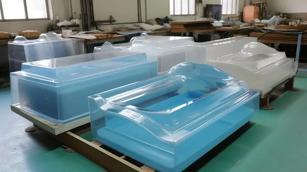
One more reason to fix radii early: mold maintenance. Deep, tight corners are where tools wear and pick up marks first, so a radius chosen for formability is also a radius that holds up over thousands of cycles.
With 20+ vacuum forming machines across the plant and monthly capacity in the 100,000–200,000 piece range, corner geometry proven at prototype scale transfers to volume without re-deriving the process. The radius you validate early is the radius the production line keeps.
FAQ
What is the minimum inside corner radius for vacuum forming?
One sheet thickness is the practical floor, and 1.5–2× is safer for deep draws or stiffer materials. Below that, expect bridging and local thinning regardless of vacuum strategy.
Do sharp corners always cause webbing?
No. Webbing appears when two features are tall and close together with nowhere for excess material to go. Shallow parts with generous spacing can hold tighter corners, but the risk climbs with draw depth.
Can pressure forming hold a sharper corner than vacuum forming?
On outside, cosmetic surfaces, yes — positive air pressure presses the sheet into detail that vacuum alone cannot reach. Drawn inside corners still need a radius, because the material physics does not change.
Does a larger corner radius increase tooling cost?
Marginally at most, since the radius is machined into the same tool surface. The expensive path is changing radii after forming trials, which means tool rework and a repeat first article.
Which materials tolerate tight corners best?
ABS and PC/ABS are the most forgiving in heavy gauge draws. PC and PMMA need larger radii to avoid cracking. For formed equipment enclosures, remember that UL 94 classifies the flammability of plastic materials, and the thinning left at corners must preserve enough wall to meet the rating the enclosure is specified to.
To keep exploring corner design, draft strategy, and tooling choices, walk through our vacuum forming guide, or review how a China-based vacuum forming manufacturer approaches heavy gauge housings and trays from prototype to production.
-
Draw ratio: the ratio of formed part depth or surface area to the original flat sheet area; higher draw ratios concentrate strain on corners. ↩
-
Webbing: excess sheet that folds or bridges between closely spaced mold features when the material takes the shortest path instead of seating into the tool surface. ↩
-
HDT: heat deflection temperature, the temperature at which a plastic specimen deflects a defined amount under a specified flexural load. ↩
-
Draft angle: the taper applied to drawn walls so a formed part releases from the mold without dragging, galling, or marking the surface. ↩