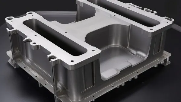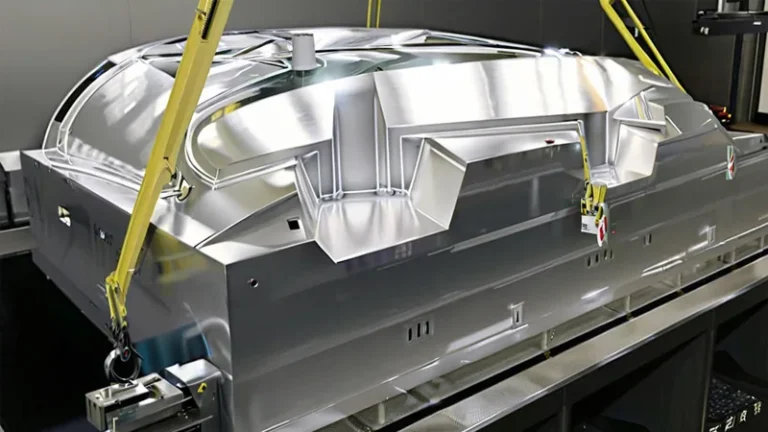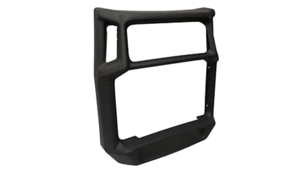
Deep parts look simple on a CAD screen and unforgiving on a forming table. The number that decides whether a thick-gauge design can be vacuum formed at all is the draw ratio, and most feasibility disputes between buyers and formers trace back to how that number was calculated. This article sets out the two definitions in use, the step-by-step arithmetic, the material limits, and the first-article checks that decide whether a housing, tray, or structural cover comes off the tool clean instead of tearing, webbing, or thinning out in the corners.
- Draw ratio compares how far the sheet is stretched against how much sheet is available, and it predicts wall thinning before the first trial forming.
- Two definitions are in common use: a simple depth-to-opening (linear) ratio and an area-based ratio; the area-based figure is the one to use for feasibility sign-off.
- Under ideal conditions, final wall thickness ≈ starting sheet thickness ÷ area draw ratio.
- Corners carry a far higher local draw ratio than the flat-wall average, and corner radii are where heavy-gauge parts fail first.
- Material sets the ceiling: HDPE tolerates aggressive draws, while PC and PMMA demand conservative ones.
- You can verify any supplier’s arithmetic with three numbers from your own drawing: depth, smallest opening, and developed surface area.
What Is Draw Ratio in Heavy-Gauge Thermoforming?
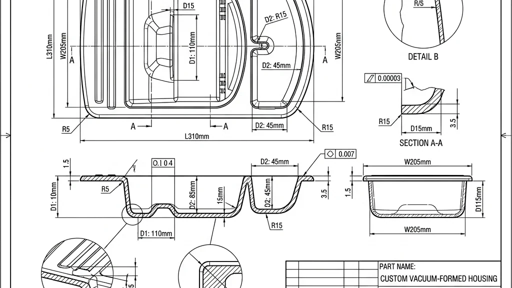
Draw ratio expresses the relationship between the sheet a former clamps and the surface the finished part has to cover. It is the primary feasibility check for vacuum forming deep parts, and it should be calculated from the drawing before a mold is quoted. The vacuum forming process overview covers the basics; this article focuses on the number that governs deep designs.
Two definitions are used in practice, and mixing them up is the most common source of feasibility arguments.
The first is the linear draw ratio: part depth divided by the smallest opening the sheet must stretch across. A cover 350 mm deep with a 600 mm opening has a linear draw ratio of roughly 0.58. It is quick to compute and useful for screening, but it ignores shape — a part with a huge flat floor scores the same as one that is uniformly deep.
The second is the area draw ratio: the developed surface area of the formed part divided by the clamped sheet area inside the seal frame, and the figure that governs predicted wall thinning1. Forming stretches sheet, it does not compress it, so every unit of new surface is paid for in thickness:
t_final ≈ t_start ÷ DR_area
A part with an area draw ratio of 2.5 formed from 5 mm sheet can average no more than about 2 mm of wall even in the ideal case, and real parts always land below the ideal at corners and drawn walls.
Heavy-gauge thermoforming sharpens the stakes. A 6–10 mm sheet carries real mass, sags under its own weight in the oven, and every extra millimetre of depth multiplies the strain the corners must absorb.
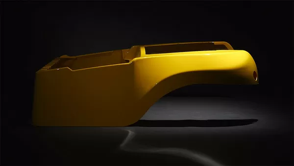
ZetarVac processes sheet from 0.5 to 15 mm and forms parts up to about 2,500 mm long on 20+ vacuum forming and thermoforming machines. At a 10 mm starting gauge, an area draw ratio of 3 leaves roughly 3.3 mm of average wall, so assuming the wrong starting gauge by even 1 mm moves the predicted wall by about a third of a millimetre — enough to miss a structural tolerance.
How Do You Calculate Draw Ratio for a Thick-Wall Part?
Four steps, all doable from a drawing before any mold is cut: fix the depth and smallest opening, compute the linear ratio, develop the surface area, and divide starting thickness by the area draw ratio.
Step 1 — fix the depth and the smallest opening. Measure the deepest drawn feature and the narrowest opening the sheet must stretch over; the opening, not the overall width, governs the linear figure. Step 2 — compute the linear draw ratio by dividing depth by that opening. Step 3 — develop the surface area. In CAD, measure the total tool-contact surface and divide it by the clamped area inside the seal frame; for prismatic parts you can approximate by hand as floor area plus each wall panel, plus a 10–15% allowance for radii and draft.
Step 4 — divide the starting thickness by the area draw ratio to get the ideal average wall.
A worked example makes the arithmetic concrete. Take an agricultural tray with a 1,000 × 600 mm footprint, 350 mm deep, formed from 5 mm ABS:
- Clamped area with a 50 mm seal margin all round: 1,100 × 700 = 770,000 mm²
- Developed surface: floor 600,000 + long walls 700,000 + short walls 420,000 + radii allowance ≈ 280,000, totalling about 2,000,000 mm²
- Area draw ratio ≈ 2.6
- Ideal average wall ≈ 5 ÷ 2.6 ≈ 1.9 mm, with the deepest corners running thinner still
If the application needs 2 mm minimum wall anywhere, the design is already at the limit with 5 mm sheet. The fix is either a thicker starting sheet or shallower cells — a decision to make on paper, not on the machine.
Two cautions keep the arithmetic honest. The formula assumes uniform biaxial stretch, which real forming never delivers, so treat the calculated value as a ceiling rather than a specification. And the ceiling itself comes from the material: ASTM D638 specifies the standard tensile test used to measure the tensile properties and elongation at break of plastics,2 and a sheet whose tensile data cannot fund the surface growth an area draw ratio demands will fail regardless of how clean the numbers look.
What Draw Ratio Can Thick-Gauge Sheet Handle?
It depends on the material, the gauge, and the tool design, but working windows exist for screening a concept. Treat the rankings below as starting points to confirm with a trial, not as guarantees.
| Material | Deep-draw behaviour | Draw-ratio headroom* |
|---|---|---|
| HDPE | High melt strength and elongation; the most forgiving deep-draw material | Highest |
| PP | Good stretch but a narrow heating window; warpage control matters | High |
| ABS | Balanced formability; the default for housings and structural covers | High |
| PVC | Good detail and stretch; degradation risk if overheated | High |
| PC/ABS | Slightly less forgiving than ABS; common on equipment enclosures | Moderate |
| PC | Strong but less extensible; needs precise sheet heating | Moderate |
| PMMA | Limited elongation; keep draws shallow and radii generous | Low |
| PP/GF | Glass fibre restricts stretch; design for modest draws | Lowest |
*Relative screening guidance for heavy-gauge sheet; the workable numeric range depends on the actual resin, the delivered gauge, and the tool design, so confirm with a trial forming.
Heat capability enters the decision too. ISO 75-2 specifies the test method for determining the deflection temperature of plastics under flexural load,3 and formers use that value to judge how far a sheet can be heated toward its forming window before it sags uncontrollably. A material that cannot be heated reliably into its forming window will never realize its theoretical draw ratio, whatever the tensile chart suggests. The SPE Thermoforming Division publishes deep-draw troubleshooting guidance that is worth cross-checking against any supplier’s claimed limits.
"If the average draw ratio is below three, the part will form without trouble."False
The average hides the corners, where local stretch can run two to three times the flat-wall value. Parts fail first at the smallest radius, so a comfortable average combined with tight corner radii still tears, webs, or thins below specification.
"Corner radius, not the average draw ratio, decides whether a deep draw survives."True
Enlarging a 5 mm corner radius to 20 mm can halve the local strain peak while the average draw ratio stays unchanged. Review the smallest radii on the drawing before debating the average.
How Does Draw Ratio Affect Wall Thickness and Quality?
Draw ratio sets the average wall thickness, while tool orientation and part geometry decide how that thickness is distributed. The two failures to control on deep designs are corner thinning and webbing.
With a male tool the sheet drapes over the form, and the first-contact surface stays close to starting gauge while the last-stretched regions thin most. With a female tool the sequence reverses and the bottom corners thin first. For deep parts, tool orientation is therefore a wall-thickness decision, not merely a cost decision.
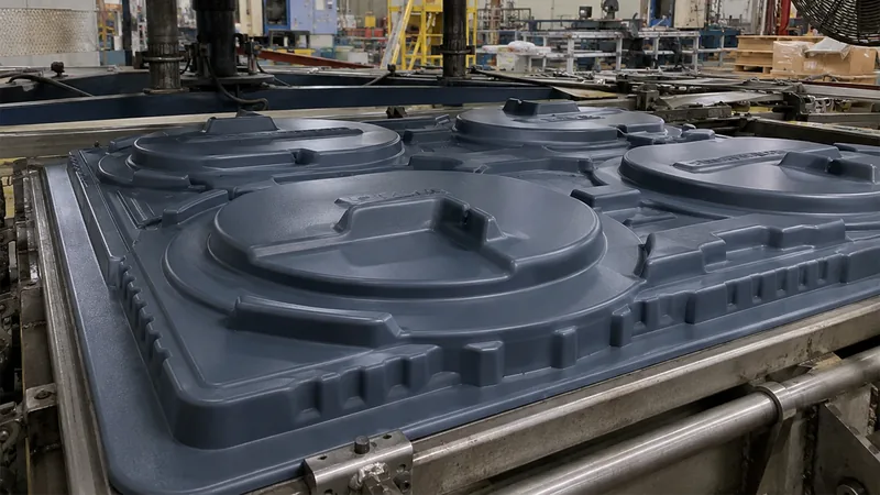
Webbing is the classic cosmetic failure on aggressive draws: excess sheet bridges between tall features and freezes as a fold across an otherwise flat wall. Prestretch4 — bubbling, plug assist, or a controlled billow before vacuum is applied — redistributes material before it freezes, and it is the standard countermeasure alongside wider mold spacing and vacuum holes placed along the web path rather than only in the deep pockets.
Three checks belong on every deep-draw first article. Map actual thickness at the predicted worst points: the bottom corners of female cavities, the top radii of male forms, and any sharp internal edge. Compare the measured minimum with the ideal value from your calculation; a large gap points to a heating or tooling issue, not bad arithmetic. And re-run the calculation with the delivered sheet’s actual gauge rather than the nominal gauge, because sheet tolerance alone moves the answer by several percent.
"Wall thickness comes out uniform as long as the draw ratio is acceptable."False
Forming is a stretching process, so thickness always grades from first-contact areas toward last-stretched corners. Accepting a draw ratio means accepting a thinning map, and trim lines, mounting bosses, and stiffening ribs must be placed with that map in view.
"Draw ratio predicts the best possible wall; the real part gets measured."True
The formula gives an ideal ceiling under perfect biaxial stretch. A capable supplier quotes the predicted value, then verifies the actual minimum wall on first articles before releasing the job to production.
Once the thinning map is known, trimming closes the loop between prediction and delivery.
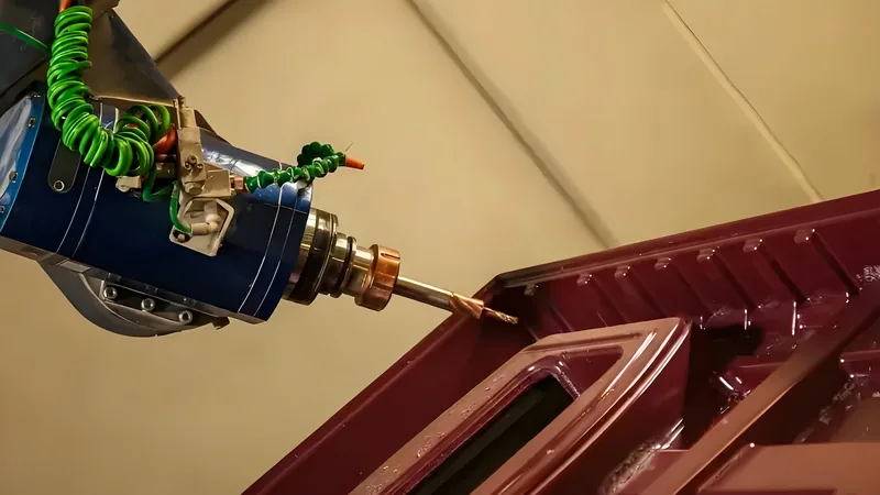
Formed parts at ZetarVac are trimmed on a 5-axis CNC centre whose outline follows the forming tool. A thin corner cannot be machined away afterwards — if the thin zone sits inside the trim line, the wall-thickness fix has to happen at the drawing and tooling stage.
When Should You Redesign Instead of Pushing a Higher Draw Ratio?
When the calculated thinning already breaches the minimum wall, process tuning rarely saves the design, and the cheaper path is usually a geometry change.
Keep internal radii at roughly 1.5–3× the starting sheet thickness — the single highest-value change on deep parts. Add 2–5° of draft to drawn walls so the part releases without fighting the tool. Split overly deep geometry into two shallower housings joined by fasteners or welding. Consider pressure forming where a female tool is needed for cosmetic detail on a deep part, since the added forming pressure supports sharper detail on aggressive draws. And where the schedule allows a material change, moving from PC toward ABS or HDPE buys real draw-ratio headroom.
Wall-thickness distribution interacts with every one of these choices; the dedicated article on wall thickness reduction in heavy-gauge thermoforming works through them in detail. Cost discipline matters just as much: radius and draft changes made before tooling are engineering hours, while the same changes after a failed trial are mold rework, as covered in the guide to cost control in thermoforming.
FAQ
Is draw ratio the same as the depth-to-width ratio?
No. Depth-to-width is the linear figure, a quick screening number, while the area draw ratio — developed part surface over clamped sheet area — is the number that predicts thinning. Screen with the linear figure and sign off feasibility with the area figure.
What is a good draw ratio for vacuum forming thick sheet?
For most heavy-gauge materials, an area draw ratio of 2–3 forms comfortably, 3–4 is workable with sound tool design and forgiving materials such as ABS or HDPE, and values above 4–5 should be treated as specialist territory to be proven by trial. Corners set the real limit.
How do I convert draw ratio into expected wall thickness?
Divide the starting sheet thickness by the area draw ratio. From 8 mm sheet at a draw ratio of 2.5, the ideal average wall is 3.2 mm; expect the last-stretched corners to fall below that, and verify them on the first article.
Does draw ratio affect material selection?
Yes, often decisively. Deep designs push the choice toward high-elongation materials such as HDPE, ABS, and PP, while PC, PMMA, and glass-filled grades pull the design toward shallower draws, larger radii, or a geometry split.
What should I send to have a draw ratio checked before tooling?
Three numbers are enough for a first assessment: overall depth, smallest mold opening, and developed surface area — or simply send the 3D model. If you are evaluating a deep-draw design and want the arithmetic, material match, and expected thinning map reviewed against the tool design before anything is cut, share your drawings and talk to an engineer.
-
Draw ratio: The ratio between the developed surface area of a formed part (or its depth relative to the forming opening) and the sheet area available to form it; the primary feasibility indicator in thermoforming. ↩
-
ASTM D638: The standard test method for tensile properties of plastics, used to determine elongation at break and other tensile properties of thermoformable sheet. ↩
-
ISO 75-2: The standard test method for determining the deflection temperature of plastics under flexural load, used to compare the heat capability of sheet materials. ↩
-
Prestretch: Any technique — bubbling, plug assist, or controlled billow — that pre-distributes sheet material before final vacuum is applied, reducing corner thinning and webbing. ↩