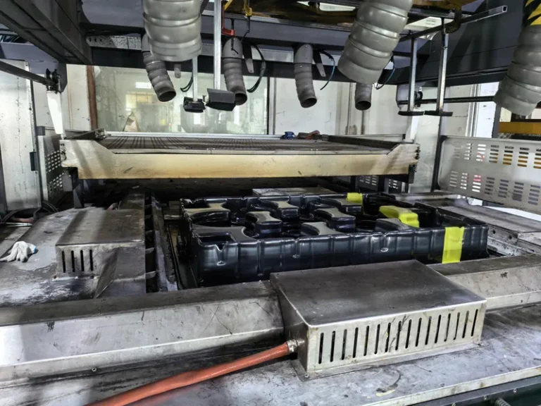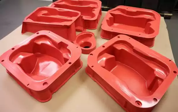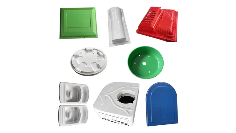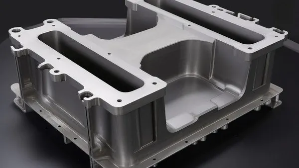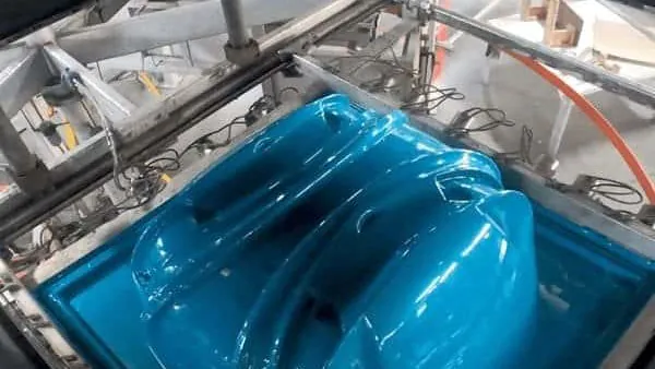
Thermoforming starts with a flat plastic sheet and ends with a three-dimensional part: the sheet is clamped, heated into its forming window, stretched against a single-surface mold by vacuum, air pressure, or both, then cooled and trimmed to final outline. It is the workhorse route for large enclosures, machine guards, trays, and structural panels where part size and production volumes make other molding routes uneconomical. This guide condenses the process windows, material decisions, tolerance expectations, defect modes, and inspection methods that decide whether a formed part succeeds in production.
- Thermoforming stretches a heated plastic sheet over a single-surface mold; vacuum forming is the most common variant for heavy-gauge industrial parts.
- Heavy-gauge work processes sheet from about 0.5 to 15 mm, with formed lengths up to roughly 2,500 mm on full-size industrial machines.
- Material choice follows the service environment: ABS for housings, PC for impact and clarity, PMMA for optical covers, HDPE and PP for chemical-resistant trays, TPE and TPV for soft liners.
- Tolerances are wider than on machined parts; keep tight bands on tool-carried features and leave free surfaces generous.
- First-article approval confirms the tool and setup, not long-run stability; sheet lot variation still needs monitoring across production.
- Standards such as UL 94, IEC 60529, and ISO 75-2 define the acceptance tests that buyers most often invoke on formed enclosures.
What Is Thermoforming and How Does Vacuum Forming Work?
Thermoforming is a sheet process: the plastic sheet is clamped in a frame, heated until it reaches a rubbery, formable state, then forced against a mold by vacuum, positive air pressure, or a mechanical plug. In vacuum forming, a vacuum drawn through ports in the tool lets atmospheric pressure do the stretching, which is why the process scales to very large parts at low tooling cost.
The cycle has four controllable stages. Clamping sets the sheet perimeter and seal quality. Heating is the longest stage on heavy-gauge work: thick sheet needs heat from both sides, and most machines use top and bottom oven banks with ceramic or cal-rod heaters. Forming is where geometry is decided — draw ratio, the relationship between part depth and the sheet area feeding it, tells you early whether corners will thin out or the sheet will web between features.1 Cooling fixes the shape: the mold-side surface mirrors the tool while the free surface shrinks on its own schedule, which is the root of most warpage and tolerance issues.
Heavy-gauge thermoforming differs from roll-fed thin-gauge work in feed and equipment. Sheet arrives as cut blanks or, for thinner gauges, by roll, and forming length on industrial machines reaches about 2,500 mm — one reason bus interior panels, machine housings, and large trays are formed rather than built up from fabricated pieces. Pressure forming adds positive air pressure above the sheet, giving sharper texture and detail than vacuum alone at the cost of a pressurized tool.
Which Materials Work Best for Heavy-Gauge Thermoforming?
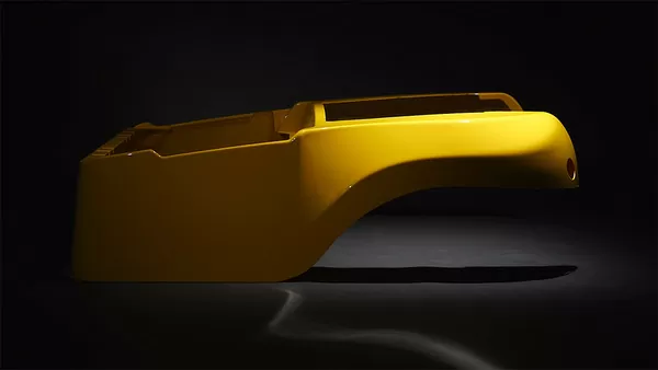
Match the resin to the service environment rather than the price list. ABS covers most indoor equipment housings; PC and PC/ABS take impact and moderate heat; PMMA delivers optical clarity for covers and displays; HDPE and PP resist chemicals in trays and liners; TPE, TPU, and TPV add soft liners, seals, and flexible sleeves over or beside rigid shells.
| Material | Typical formed applications | Why it is selected |
|---|---|---|
| ABS | Equipment housings, cases, guards, automotive interior parts | Balanced stiffness, impact strength, and a wide forming window |
| PC and PC/ABS | Clear guards, protection covers, equipment housings | High impact strength; blends moderate cost and heat behaviour |
| PMMA (acrylic) | Clear covers, luminaires, display parts, retail displays | Optical clarity and outdoor stability |
| HDPE and LDPE | Industrial trays, equipment liners, storage boxes, thin-wall packaging | Chemical resistance and low cost; LDPE suits thin-wall parts |
| PP and PP/GF | Automotive interior parts, trays, boxes, equipment liners, structural parts | Chemical resistance and living-hinge behaviour; glass fill adds stiffness |
| PVC | Trays, packaging, industrial enclosures, liners | Easy forming with useful flame performance |
| ASA | Outdoor equipment housings, automotive exterior parts | Weatherability without painting |
| PA6/PA66 and POM | Special industrial structural and precision parts | Stiffness and wear performance beyond common sheet-forming norms |
| TPE, TPU, TPV | Soft liners, seals, flexible sleeves, industrial protection parts | Elastomeric function combined with formed rigid shells |
The material library on the production floor covers PVC, ABS, HDPE, LDPE, PP, PC, PMMA, PA6/PA66, POM, TPE, TPU, TPV, PC/ABS, ASA, and PP/GF. In practice this means one supplier can form a PC medical equipment housing with custom cut-outs and mounting holes, an ABS multi-cavity seedling tray, and a PMMA high-clarity display cover without changing process families.
For enclosures near electrical components, flammability is a gate, not a preference. UL 94 defines the flammability classification of plastic materials, and it is the standard behind most formed equipment enclosures, with ratings such as HB or V-0 written directly into housing specifications.2 Where a formed cover must keep out dust and water, IEC 60529 defines the degrees of protection an enclosure provides, and the resulting IP rating depends as much on gasket design and trimming quality as on the resin itself.3
How Tight Are Thermoforming Tolerances and Part Sizes?
Expect general tolerance bands of roughly ±1 % of the feature dimension on well-controlled formed parts, with tighter bands only where the feature is carried by the tool. The practical size envelope for heavy-gauge work runs from 0.5 mm to 15 mm sheet and forming lengths near 2,500 mm.
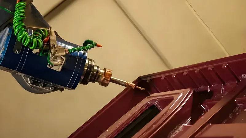
Tolerance on a formed part comes from four stacked sources: sheet thickness variation from the supplier, non-uniform sag in the oven, differential shrinkage between the mold side and the free side, and trimming accuracy. Because the mold-side surface is the only one that mirrors the tool, drawings should datum critical interfaces to that side. Trimming is the other lever: 5-axis CNC trimming follows the forming tool, so trimmed outlines repeat from part to part instead of depending on manual fit.
"Thermoforming tolerances should be specified like machined part tolerances."False
Free surfaces shrink away from the tool and shift with sheet lot, so blanket tight bands generate rejections that add cost without improving function. Datum to the mold side and leave free surfaces at commercial bands.
"Tool-carried features hold tighter tolerance than free surfaces."True
Both the forming tool and the 5-axis trimming path are tool-defined, so mounting holes and interfaces cut against those datums repeat consistently. Placing critical features there makes assemblies predictable without inflating part cost.
Sheet gauge adds its own rules. Below about 1 mm, sag control and heating uniformity dominate; above roughly 6 mm, heating time and through-thickness temperature gradients decide the cycle, and deep draws need plug assist or prestretch. Wall thickness in the finished part is never uniform: corners run thin, and a designer who needs a minimum corner thickness should state it on the drawing rather than discover it on the first article.
What Defects Occur in Thermoforming and How Are Formed Parts Checked?
The recurring defect families are webbing between close features, corner thinning on deep draws, blisters from overheated sheet, poor texture transfer, and warpage from uneven cooling. Verification is just as concrete: tensile, flexural, heat deflection, and puncture tests run against published standards on both incoming sheet and formed parts.
Each defect has a process cause you can act on. Webbing comes from excess sheet between close features — fix it with sheet width, plug geometry, or web rails on the mold. Corner thinning scales with draw ratio; redistribute the stretch with plug assist or prestretch before the vacuum pulls the sheet tight. Blisters mean the sheet left its forming window, usually an oven zone set too hot or heating time stretched past the material limit. Warpage traces back to asymmetric cooling, so mold temperature control and uniform air flow on the free side matter as much as the vacuum layout.
Mechanical verification follows standard methods. ISO 527-2 specifies the tensile test run on thermoformed sheet, and ASTM D638 serves the same role for sheet and formed-part validation. ASTM D790 governs flexural properties, which is how the stiffness of formed panels and enclosures is compared across material candidates. ISO 75-2 defines the heat deflection temperature under load — the number that predicts whether a housing near a heat source will hold shape in service — and ISO 6603-2 covers instrumented puncture impact for parts exposed to impact loads.4 For clear formed parts, ISO 13468 defines total luminous transmittance, the acceptance number behind PMMA and PC display covers.
"Once the first article passes inspection, the process is stable for production."False
First-article approval confirms tool geometry and setup, not drift. Sheet lot changes and oven calibration shifts move wall distribution and shrinkage during the run, so stability comes from monitored checkpoints, not a single approval.
"Process stability needs periodic checks across the production run."True
Sampling formed parts at defined intervals catches sheet lot drift and oven behaviour before it becomes scrap. Pairing that sampling with supplier sheet certificates keeps wall distribution and dimensions inside agreed bands over long runs.
What Drives Thermoforming Cost and Lead Time?
Four levers dominate: tooling, sheet, cycle time, and trimming. Single-surface molds keep tooling cost low, which is why thermoforming stays economical at prototype and small-batch volumes as well as large runs. Sheet utilization — how much of the blank becomes part versus skeleton — is the largest recurring material cost, so nesting and sheet sizing deserve attention at design time. Cycle time scales with sheet thickness through both heating and cooling, and trimming is a fixed operation per part on the 5-axis centre.
The plant runs more than 20 vacuum forming and thermoforming machines among 45+ total production lines, with reference monthly capacity of roughly 100,000 to 200,000 pieces. Prototyping, small batch, and large batch production are all supported, which matters when a heavy-gauge program starts at pilot volumes and later scales without a process change.
Design decisions carry cost consequences that are far cheaper to fix on paper. Generous draft angles and radii reduce thinning and webbing risk; specifying texture only where it is visible keeps pressure-forming requirements down; consolidating several fabricated parts into one formed shell removes fasteners and assembly labor. For a structured breakdown, see the guide on cost control in thermoforming and the follow-up on cost reduction in thermoforming, which walk through sheet utilization, cycle-time levers, and tooling trade-offs in detail.
FAQ: Common Questions About Thermoforming
How thick can thermoformed sheet be?
Heavy-gauge thermoforming typically processes sheet from 0.5 mm to 15 mm, with formed parts up to about 2,500 mm long. The useful range depends on material and machine: thick sheet needs two-sided heating and longer cycles, while thin sheet suits packaging and covers.
Is vacuum forming economical for small production runs?
Yes — single-surface tooling keeps upfront cost low, so prototyping and small batches are practical. Unit economics improve at larger volumes, but the process does not require them to break even.
Which materials can be vacuum formed?
Most commodity and engineering thermoplastics: ABS, PC, PC/ABS, PMMA, HDPE, LDPE, PP, PVC, ASA, and glass-filled PP, plus specialty PA6/PA66, POM, TPE, TPU, and TPV for liners, seals, and structural parts.
What tolerance can a formed enclosure hold?
General features around ±1 % of dimension on a controlled process, with tighter bands on tool-carried and CNC-trimmed features. Datum drawings to the mold side and concentrate tight bands on mounting interfaces.
How are formed parts trimmed and finished?
On 5-axis CNC trimming centres, which follow the forming tool to cut outlines, cut-outs, and mounting holes consistently. Edge finishing and gasket fitting follow, depending on whether the part is an IP-rated cover or a structural panel.
If you are mapping a formed-part program, the next useful step is depth, not a quotation. Explore the full vacuum forming process, material options, and design guidelines in the ZetarVac vacuum forming guide, or review how a heavy-gauge thermoforming supplier in China structures tooling, materials, and inspection for equipment housings and industrial parts.
-
Draw ratio: The ratio between the depth of the formed part and the width of the sheet area feeding it; higher draw ratios mean greater corner thinning and webbing risk. ↩
-
UL 94: The standard for flammability of plastic materials; ratings such as HB or V-0 classify how a resin burns and are commonly specified for equipment enclosures. ↩
-
IP code: The ingress protection classification defined in IEC 60529, describing how well an enclosure keeps out dust and water. ↩
-
HDT: Heat deflection temperature, the temperature at which a plastic deflects a defined amount under flexural load, measured under ISO 75-2 or ASTM D648. ↩