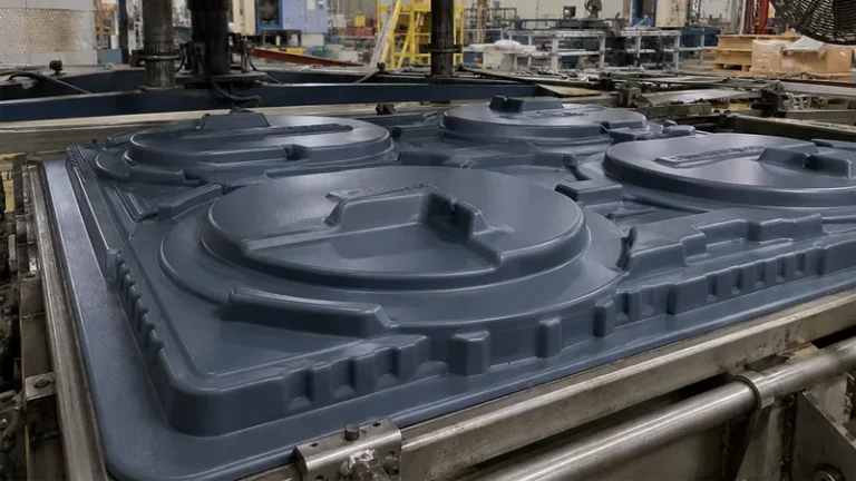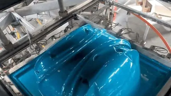
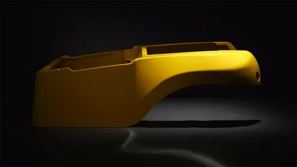
Thermoforming earns its place on tooling cost, speed and part size. A heavy-gauge enclosure that would need expensive matched tooling elsewhere can be formed from a low-cost tool in days. But the process has hard limits, and the expensive way to learn them is after the forming tool has been cut. This article maps the real limitations of thermoforming and vacuum forming — geometric, dimensional, material and economic — with the engineering checks that catch each one before it turns into a tool revision or a scrap problem.
- Thermoforming controls geometry on one surface only: tolerance and surface detail concentrate on the tool side, while the free surface inherits sheet texture and thickness variation.
- Wall thickness is redistributed, not held. Deep draws thin the sheet, so finished gauge must be verified on trial formings, never assumed from the sheet you bought.
- Draft angles, corner radii and draw ratio define the geometric envelope; undercuts, sharp internal corners and deep uniform pockets are where designs get rejected.
- Material properties are bounded by available sheet and changed by forming heat history, so they are validated on formed parts, not resin datasheets.
- Most limitations yield to design and process work. The ones that do not — very high part counts and two-sided cosmetic tolerance — are project decisions, not process tweaks.
What Are the Real Limitations of Thermoforming?
Thermoforming is limited in four areas: geometry, wall-thickness distribution, material behavior and process economics. Draft angles, draw depth and corner radii cap what a single-sided tool can reproduce; forming redistributes sheet thickness instead of holding it; material choice is bounded by the sheet that exists in the right gauge; and unit economics favor moderate volumes and large parts. All four limits are testable before tooling is committed.
The limits look different depending on who you ask. A product designer meets them as draft and radii rules. A procurement engineer meets them as thickness scatter and sheet-lot variation. A plant engineer meets them as webbing, sag and thinning corners. None of these are exotic defects — they are the predictable consequences of stretching one heated sheet over a single tool, which is exactly why they can be checked early. The vacuum forming process page walks through the forming sequence itself if you need that base first.
Where Does Thermoforming Hit Geometric Limits?
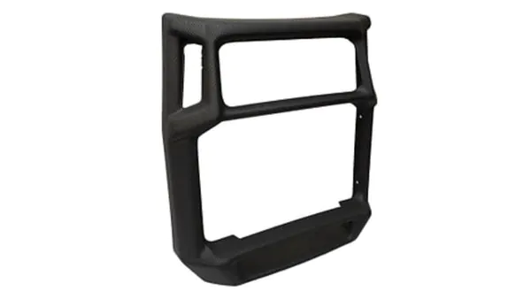
Geometry is limited by the fact that only one surface of the part touches a tool. Draft angles of roughly 2–5 degrees, generous corner radii and a controlled draw ratio keep a part formable; undercuts, sharp internal corners and deep, uniform pockets are the classic geometry that forces a design change or a more complex tool.
Draft and radii are not cosmetic preferences. In vacuum forming, the free surface is shaped by air pressure and sheet tension alone, so sharp internal corners leave the sheet bridging instead of contacting the tool, which produces webbing and unpredictable local thickness. A practical rule: radius every internal corner as generously as the function allows, and give female-form parts more draft than male-form parts, because material has to be pulled into the cavity rather than draped over it.
Undercuts are the hard geometric wall. A formed part cannot be pulled off an undercut in rigid tooling, so either the tool gets collapsible or moving sections — cost and maintenance the project has to justify — or the parting line moves. Draw depth works similarly: as the area draw ratio1 climbs past roughly 4:1 for many rigid materials, thinning and cooling behavior get difficult to hold, and the honest answer is usually a shallower draw or a thicker starting sheet, not process heroics.
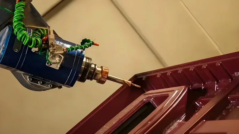
Forming capacity is bounded by real equipment, and it is worth checking against your envelope: sheet from 0.5 to 15 mm processed, forming lengths up to about 2,500 mm, and 5-axis CNC trimming of formed parts. Large housings and machine covers that fit inside that window are exactly the parts heavy-gauge thermoforming handles best.
Within that envelope, tolerance strategy matters more than tolerance magnitude. Specify which surfaces are critical and let the process own the rest — this is a design conversation, not a quote-time surprise.
"Thermoforming can hold tight tolerances on every surface of a part."False
Only the tool-side surface carries mold detail and stable dimensions. The free surface is formed by air pressure and sheet sag, so its position moves with local thickness variation — and thinning shifts outside dimensions even when the tool is perfect.
"Critical dimensions belong on the tool-side surface, and the free side gets wider tolerance."True
Mold temperature, vacuum distribution and sheet contact are all best controlled on the tool side, so that is where dimensional repeatability lives. Declaring this at design stage keeps the tolerance stack honest and avoids machining features that forming cannot locate.
Why Is Wall Thickness in a Formed Part Never Uniform?
Forming stretches one heated sheet over the tool, so thickness is redistributed rather than preserved. The regions that draw deepest end up thinnest, while the clamped flange stays close to the starting gauge — which is why the sheet thickness you buy is not the wall thickness you get.
The redistribution is systematic, not random. Deep-drawn corners commonly run 30–50% below nominal sheet thickness depending on material, sheet temperature and tool geometry, while flange areas remain near nominal. That spread is a design input: if a corner wall must carry load or meet a minimum stiffness, the starting sheet is overgauged so the thinned region still clears the requirement, or the geometry is opened up to reduce local stretch.
Thin corners are also where cosmetic and structural defects cluster. Overheated sheet produces bubbles and splay marks, and thin corners concentrate them; the dedicated article on bubbles and splay marks in heavy-gauge thermoforming covers the heating-side causes. The design-side fix is the same in both cases: control sheet temperature uniformly, and avoid geometry that forces extreme local stretch.
"If the sheet is 6 mm, every wall of the finished part is 6 mm."False
Forming stretches the sheet, so thickness follows the draw, not the stock. Deep corners thin out while flanges stay near nominal — a part quoted from stock gauge can miss a minimum-wall requirement in exactly the corners that matter.
"Finished wall thickness is a prediction and verification task, not a stock property."True
Thickness distribution depends on draw ratio, sheet temperature and tool design, so it should be estimated at design stage and then section-cut from trial formings. Checking trial parts before the production run turns thinning from a field failure into a known number.
How Do Material Limitations Show Up in Formed Parts?
Material limits appear in two forms: you can only specify what exists as sheet in the right gauge, color and width, and forming itself changes the properties you are buying. Heat history, stretching and frozen-in orientation mean datasheet values have to be re-validated on formed parts.
Validation is not optional engineering theater. Tensile properties of formed sheet and parts are typically measured to ASTM D638, the standard tensile test for rigid plastics, which defines the specimen geometry and test speed used to confirm that forming has not degraded tensile performance beyond the acceptance band; ISO 527-2 is the ISO-side equivalent for the same purpose. For panels and enclosures, stiffness is checked in flexure to ASTM D790, which constrains how a formed enclosure resists bending loads in service.
Thermal limits matter just as much for equipment housings. Heat deflection temperature2 under flexural load, defined in ISO 75-2, sets the practical service-temperature ceiling before a formed panel starts to sag under its own load path. For enclosures around electrical equipment, flammability is governed by UL 94, which grades materials from HB through V-0 and 5VA by burn behavior — the rating many formed equipment covers are required to meet. Where a cover is specified as an ingress barrier, IEC 60529 defines the IP code3 the formed geometry and sealing must actually achieve.
Sheet selection then becomes a matching exercise. PC/ABS4 is the workhorse for equipment housings and automotive interiors; ASA holds up outdoors; PC gives clear protection covers; PMMA serves high-clarity covers and retail display parts, which the acrylic thermoforming process article covers in detail. HDPE, PP and TPE cover industrial trays, liners and soft sealing. Picking from a real library like this keeps the sheet source practical instead of aspirational.
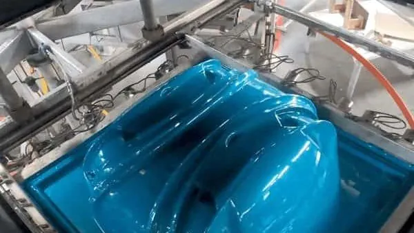
The plant material library spans PVC, ABS, HDPE, LDPE, PP, PC, PMMA, PA6/PA66, POM, TPE, TPU, TPV, PC/ABS, ASA and PP/GF — from soft liners and seals to glass-filled structural parts. That range exists because heavy-gauge applications pull in opposite directions: impact resistance, outdoor stability, clarity and stiffness rarely live in one resin.
What Do Thermoforming Limitations Mean for Cost and Lead Time?
The limitations convert directly into cost: overgauged sheet buy, web waste, trimming and secondary machining, and at least one trial forming loop. Tooling stays cheap and fast — the core advantage of the process — but unit cost remains higher than high-volume molding processes, which is why forming fits prototypes through large batches rather than millions of parts.
The cost structure is specific. You buy sheet thicker than the finished wall, so material cost scales with thinning, not just part size. Complex trimmed outlines consume 5-axis machining time, which is why trim-friendly parting lines are worth real money. And every design change after tooling costs a tool revision, which is why the checks in this article run before the tool, not after. The article on cost control in thermoforming breaks these levers down in detail.
Volume capability spans the whole middle of the market: 20+ vacuum forming and thermoforming machines across 45+ total production lines, with reference monthly capacity around 100,000–200,000 pieces and prototyping, small batch and large batch production all supported. A process often dismissed as prototype-only can carry real volume — the limit is millions of parts, not thousands.
One cost myth deserves a direct answer, because it shows up in every sourcing conversation.
"A first article that passes inspection proves the process is stable."False
First articles come from the most controlled sheet lot and the most careful setup. Sheet-lot variation, regrind percentage and ambient conditions all shift sag and thinning across a production run, so a single golden part says nothing about lot 40.
"Stability is demonstrated across sheet lots and defined measurement points, not on one part."True
Acceptance planning should include formings from more than one sheet lot and fixed measurement locations on the thinnest predicted corners. That is what makes the thickness and dimensional data mean something at shipment time.
Which Limitations Can Design Work Around, and Which Cannot?
Most thermoforming limits yield to design: draft, radii, tool-side critical features, overgauged sheet and post-form machining absorb the geometric and thickness constraints. The limits that do not yield are volume economics and two-sided cosmetic tolerance — no amount of design work turns forming into a process for two finished surfaces at millions of parts.
| Limitation | Engineering consequence | Practical workaround | How to verify |
|---|---|---|---|
| One-sided tool contact | Free surface carries no detail and drifts with thickness | Put critical features on the tool side; trim or machine the rest | Dimensional check on trimmed outline |
| Draw-induced thinning | Deep corners fall below nominal gauge | Overgauge the sheet, open radii, reduce draw depth | Section-cut trial formings |
| Undercuts | Rigid tool cannot release the part | Redraft the geometry or move the parting line | Formability review before tooling |
| Sheet-lot property scatter | Stiffness and thermal limits shift between lots | Tighter sheet specification, lot-based validation | Tensile and HDT checks on formed sheet |
| Complex trim geometry | 5-axis machining time grows with outline complexity | Design a trim-friendly parting line early | Trim cycle estimate at quote stage |
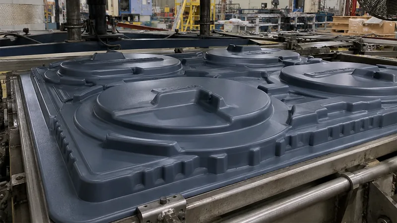
Pressure forming deserves one honest mention here: adding air pressure on the sheet side sharpens cosmetic detail on the free surface and narrows the two-surface gap, at higher tool cost. It widens the envelope; it does not remove the underlying physics.
FAQ
Can thermoforming produce thick, structural parts?
Yes. Heavy-gauge thermoforming processes sheet from 0.5 to 15 mm, and structural enclosures, machine covers and industrial trays are routine applications. The structural limits come from material choice and thickness distribution, not from the process refusing thick sheet.
How deep can a part be drawn before thinning becomes a problem?
It depends on the material and the area draw ratio, but beyond roughly 4:1 most rigid materials get difficult: thinning concentrates in corners and webbing risk rises. Treat that as a design-review trigger, and verify with trial formings rather than calculation alone.
Can formed enclosures meet flame and ingress requirements?
Yes, when the sheet grade and geometry are selected for it. Many formed equipment covers are built on UL 94-classified materials, and ingress-protected covers are designed and validated against the IEC 60529 code. The requirement has to be named early so the right sheet is sourced.
Why does my formed part sag or warp near service temperature?
Formed parts keep forming stress, and the material heat deflection temperature sets the ceiling for sustained load at temperature. If a panel is sagging in service, the fix is a higher-HDT material, geometry that shortens the unsupported span, or both — not a longer annealing hope.
When is thermoforming the wrong choice?
At very high part counts with tight tolerances on both finished surfaces, the process economics and physics stop working: unit cost stays high and one surface is uncontrolled. That is a project-level decision, and recognizing it before tooling is the cheapest engineering win available.
To go deeper on any of these limits, explore the vacuum forming guide for the full process picture, or see how a China-based vacuum forming manufacturer structures heavy-gauge projects from sheet selection through 5-axis trimming. Both walk through the process in the order a design engineer actually meets it.
-
Draw ratio: The ratio of formed part surface area to original flat sheet area; higher draw ratios mean more stretching and therefore more thinning. ↩
-
HDT: Heat deflection temperature, the temperature at which a standard plastic bar deflects a defined amount under flexural load, specified in ISO 75-2. ↩
-
IP code: The ingress protection rating defined in IEC 60529, classifying how well an enclosure excludes dust and water. ↩
-
PC/ABS: A polycarbonate/ABS blend that combines polycarbonate impact resistance with ABS processability, widely used for equipment housings. ↩