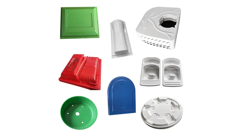
Draft angle rarely gets attention in early design reviews of a thermoformed part, yet it decides whether that part releases from the tool cleanly or comes off distorted, scored, and out of tolerance. In heavy-gauge vacuum forming, where processed sheet commonly runs from 0.5 to 15 mm thick, the cooling plastic shrinks onto the mold with real force. Draft is the taper that lets it let go.
This article covers what draft angle does in a thermoforming process, how much taper different features need, which defects trace back to insufficient draft, and how to specify the value so that mold makers, trim fixtures, and inspection plans all stay consistent. The numbers given are engineering practice ranges — the final value always depends on the material, the draw depth, and the machine.
- Draft angle is the taper built into every near-vertical wall of a thermoformed part; it exists because the sheet shrinks onto the mold as it cools.
- Male (positive) features need more draft than female (negative) features — roughly 2–5° versus 1–3° as common practice ranges.
- Too little draft shows up as webbing between features, surface scoring at ejection, warped sealing flanges, and dimensional drift across the run.
- Textured surfaces need extra draft — a common rule of thumb is about 1° of additional taper per 0.25 mm of texture depth.
- Draft must be fixed on the part drawing before forming tooling is cut, because trim fixtures and assembly interfaces inherit the formed geometry.
- Prototype forming can validate a draft assumption on a real part before production tooling is committed.
What Is Draft Angle in Thermoforming?
Draft angle is the deliberate taper, measured in degrees, between a formed wall and true vertical, added so the cooled part releases from the mold instead of locking onto it. It exists because thermoplastics contract as they cool, and that contraction clamps the sheet around every near-vertical surface. With enough draft the part drops free; without it, release force distorts the geometry.
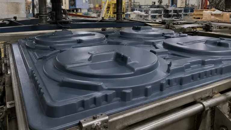
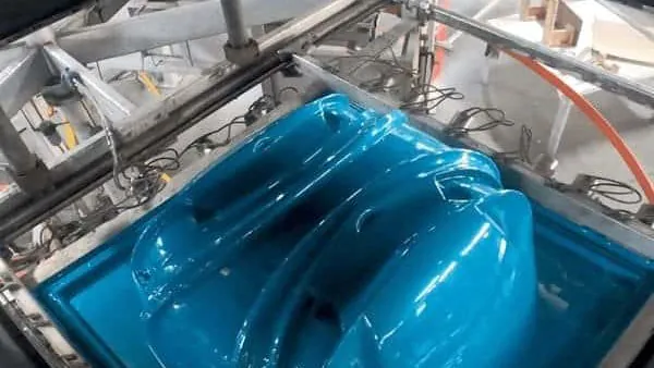
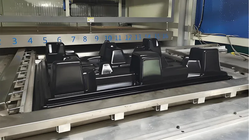
The mechanism is straightforward. In vacuum forming, a heated plastic sheet is sealed against a mold and atmospheric pressure pushes it into contact. The surface touching the tool freezes first while the outer surface is still stretched and hot. As the whole sheet cools toward its heat deflection temperature1, it contracts — onto male cores, away from female cavity walls. On a perfectly vertical wall, that contraction creates full contact pressure with no sliding component; add a few degrees of taper and the same shrinkage produces a small separating force across the whole wall.
This is why draft is not a styling preference. It is compensation for a physical event — thermal contraction under contact — that happens on every part. Depth amplifies it: the deeper the wall, the longer the contact length, and the larger the absolute interference at the base if the wall is straight.
Two surface types sit outside this logic. Horizontal planes parallel to the sheet carry no draft requirement, and shallow domes or radiused tops form freely. The problem is always the near-vertical wall, and the steeper the wall relative to the draw direction, the more the release condition approaches a full mechanical lock.
How Much Draft Angle Does a Thermoformed Part Need?
Common engineering practice is 1–3° of draft on female (negative) features and 2–5° on male (positive) cores, increasing with draw depth and surface texture. Treat these as design starting windows rather than specifications: the correct value depends on material shrinkage, mold temperature, and feature depth, and it is worth confirming on a prototype before production tooling is cut.
The table below collects typical practice ranges by feature type.
| Feature | Typical draft range | Why the range applies |
|---|---|---|
| Male core, shallow draw (under 50 mm) | 2–3° | Sheet contracts onto the core as it cools |
| Male core, deep draw (over 100 mm) | 5–10° | Contact pressure accumulates along the wall length |
| Female cavity wall | 1–3° | Shrinkage pulls the part away from the wall |
| Sealing flange, vertical face | 1–2° per side | Keeps the flat land flat enough for a gasket |
| Textured surface | Add 1–2° to the base value | Pattern depth grips the sheet like a micro-undercut |
Material shrinkage sets the baseline. High-shrinkage polyolefins such as HDPE generally need more generous taper than low-shrinkage materials like PVC, PC, or ABS, because more contraction means more lock on identical geometry. Mold temperature matters as well: a warmer tool can relax contact pressure before the skin fully freezes, while a cold tool locks the sheet in place early and punishes every missing degree.
"Zero-draft vertical walls form fine as long as the mold is polished."False
A mirror polish changes surface friction, not the geometric lock. As the sheet cools it contracts onto a straight wall with no separating component, so the part has to be forced off — usually distorting the wall or scoring the surface. On production volumes that distortion repeats on every shot.
"Every near-vertical wall on a thermoformed part needs taper, typically 1–5° depending on the feature type."True
Correct. Draft converts the clamping force of thermal shrinkage into a small release component on every unit of wall area. Female walls sit at the low end of the range because shrinkage pulls the part away from them, while male cores — where the part tightens onto the tool — need the high end.
One additional degree costs almost nothing in material or function. Half a degree too little costs a release penalty on every cycle, and on a textured cosmetic panel it can cost the panel itself.
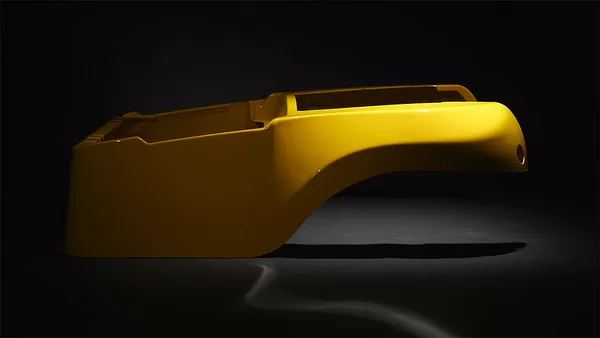
ZetarVac processes sheet from 0.5 to 15 mm and forms parts up to about 2,500 mm in length. At that scale, one missing degree of draft on a deep male core translates into a large absolute interference at the base of the wall — which is why draft is settled at the design stage, not patched after the first trial.
What Goes Wrong When Draft Is Too Tight?
Four defects trace back to insufficient draft: webbing between adjacent male features, wall distortion or surface scoring at ejection, warped flanges that no longer seal, and dimensional drift across a production run. They share one root cause — the part is mechanically locked on the tool, and release force deforms it.
Webbing2 is the classic symptom between closely spaced ribs or bosses. When the sheet bridges two near-vertical features with too little taper, it cannot slide down into the gap during forming and instead folds onto itself between them. More draft — or wider spacing — is the usual fix; process adjustments only reduce the symptom.
Draft also interacts with wall thickness distribution. When a locked part is forced off, the local strain near the tool surface concentrates thinning at the base of the wall, exactly where structural demand is usually highest. A panel that measures in tolerance at mid-wall can be measurably thinner at the corner radius, and the effect repeats identically on every cycle because it comes from the geometry, not the operator.
Release damage shows up on the cosmetic surface. Stripping a locked part drags the frozen skin across the tool, leaving shiny pull marks, whitening in higher-stress materials, or gouging where a trapped edge catches. The same locked condition that marks the surface also biases final dimensions, so wall angles belong in a first article inspection plan rather than a one-time visual check3.
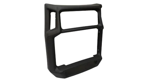
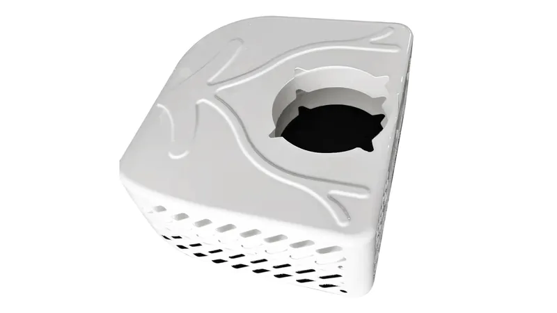
Flange distortion matters most on enclosures. Many formed equipment housings and covers are specified with a UL 94 flammability rating4 — the standard that classifies how plastic materials extinguish after a controlled flame exposure and the usual basis for formed electrical equipment enclosures. The rating belongs to the material, but the draft-controlled flatness of the flange decides whether the housing actually closes, seals, and mounts the way the enclosure design assumes.
How Draft Interacts with Mold Type, Shrinkage, and Texture
Mold direction reverses the problem. In a female (cavity) mold the part shrinks away from the tool, which is why cavity walls tolerate 1–3°; in a male (core) mold the part tightens onto the tool, which is why cores demand 2–5° or more. Parts that combine both — an outer skin with internal ribs — carry two draft budgets, and the flange where they meet is where the two budgets collide.
Texture multiplies the requirement. A widely used rule of thumb adds about 1° of draft for every 0.25 mm of texture depth, because the pattern acts as a series of micro-undercuts. A leather-grain pattern on an automotive interior panel effectively locks the sheet unless the base draft was increased before tooling.
Pressure forming shifts the trade-off slightly. Positive air pressure presses the sheet more firmly against the tool, which sharpens texture replication but also increases the effective lock, so pressure-formed cosmetic surfaces typically need the texture allowance plus a degree or two.
Shrinkage compensation interacts with draft as well. Forming tools are cut oversize by the expected shrinkage of the resin, and that allowance is applied per axis. A wall drafted for one material changes its effective release condition if the program moves to a different resin with higher shrinkage — one more reason the material decision should precede the draft decision on the drawing.
"Draft can be added by the toolmaker later without touching the part design."False
Adding draft moves the surfaces it is applied to — the flange narrows, the rib shifts, the trim line changes. Because trim fixtures and mating interfaces are built to the formed geometry, a late draft change propagates into the forming tool, the trim program, and every downstream part that bolts on.
"Draft must be fixed on the part drawing before any forming tool is cut."True
Correct. The drawing should state the degrees per surface, which surface is master on cosmetic parts, and where the tolerance band applies, so the mold maker scales for shrinkage without guessing. A prototype run then confirms the value before production tooling locks the geometry.
When specifying, keep it explicit. State draft in degrees per surface instead of a general drawing note, call out the master surface for appearance parts, and keep the flat land of a sealing flange separate from the drafted portion so the gasket path stays measurable. If a drawing review needs a second pair of eyes, ZetarVac’s service overview shows how forming, trimming, and finishing support fit together in one place.
Formed parts at ZetarVac are trimmed on a 5-axis CNC trimming centre, and the trimmed outline follows the forming tool. Draft is therefore not only a molding variable: once the forming tool exists, the trim fixture, the trimmed edges, and every downstream assembly interface inherit the drafted geometry.
FAQ: Draft Angle in Thermoforming
How much draft is enough for a first design pass?
Use 3° as a conservative placeholder on all near-vertical walls, then refine: reduce toward 1–2° on female features, increase toward 5° or more on deep male cores and textured surfaces. The placeholder exists to keep a zero-draft CAD model from ever reaching tooling review.
Does draft angle change the wall thickness of the part?
Indirectly, yes. A drafted wall distributes the stretch of the sheet more evenly than a straight wall, which reduces the localized thinning that concentrates at the base of locked vertical surfaces. The draft itself removes no material — it redistributes it.
Can vacuum forming handle undercuts or zero-draft features?
Only with trade-offs. Flexible materials, moving mold sections, or air-assist techniques can release mild undercuts, but each workaround adds cost and cycle time to every part produced. For production volumes, designing the taper in is almost always cheaper than designing around it.
Is more draft always better?
No. Excess draft on a functional face can push a mounting surface away from the mating component or thin the flange land beyond its gasket allowance. Draft should be the minimum value that guarantees clean release for the given material, depth, and texture — not a safety margin stacked on top of a guess.
How do you verify draft angle on a formed part?
On the tool, draft is checked against the CAD model before steel is cut. On the part, it is measured with an angle gauge, an optical comparator, or a scanned point cloud compared back to the drawing. The verification belongs in the first article plan, because a tool cut with the wrong taper repeats the error on every shot.
ZetarVac runs more than 20 vacuum forming machines and supports prototyping, small-batch, and large-batch production across the same 0.5–15 mm sheet range. That means a draft assumption made in CAD can be checked on a real formed part before production tooling is committed.
To keep digging into how sheet thickness, mold style, and trimming choices shape a thermoformed part, explore ZetarVac’s vacuum forming capability hub — or see how heavy-gauge projects move from first prototype to stable production with an experienced forming partner.
-
HDT: Heat deflection temperature, measured under flexural load per ISO 75-2 or ASTM D648 — commonly used to judge when a cooled sheet is rigid enough to strip from the mold without distortion. ↩
-
Webbing: A thermoforming defect in which the heated sheet folds onto itself between two closely spaced male features instead of forming cleanly into the gap. ↩
-
First article inspection: A full dimensional and visual verification of the first production parts against the drawing, used to confirm the process before volume release. ↩
-
UL 94: The flammability standard for plastic materials, classifying how specimens extinguish after a controlled flame exposure; widely specified for equipment housings and enclosures. ↩